2005 CHRYSLER CARAVAN ABS
[x] Cancel search: ABSPage 2277 of 2339
OXYGEN SENSOR HEATER MONITOR (SBEC)
DESCRIPTIONÐIf there is an oxygen sensor
(O2S) DTC as well as a O2S heater DTC, the O2S
heater fault MUST be repaired first. After the O2S
fault is repaired, verify that the heater circuit is
operating correctly.
The voltage readings taken from the O2S are very
temperature sensitive. The readings are not accurate
below 300ÉC. Heating of the O2S is done to allow the
engine controller to shift to closed loop control as
soon as possible. The heating element used to heat
the O2S must be tested to ensure that it is heating
the sensor properly.
The heater element itself is not tested directly. The
sensor output is used to test the heater by isolating
the effect of the heater element on the O2S output
voltage from the other effects. The resistance is nor-
mally between 100 ohms and 4.5 megaohms. When
oxygen sensor temperature increases, the resistance
in the internal circuit decreases. The PCM sends a 5
volts biased signal through the oxygen sensors to
ground this monitoring circuit. As the temperature
increases, resistance decreases and the PCM detects
a lower voltage at the reference signal. Inversely, as
the temperature decreases, the resistance increases
and the PCM detects a higher voltage at the refer-
ence signal. The O2S circuit is monitored for a drop
in voltage.
OPERATIONÐThe Oxygen Sensor Heater Moni-
tor begins after the ignition has been turned OFF
and the O2 sensors have cooled. The PCM sends a 5
volt bias to the oxygen sensor every 1.6 seconds. The
PCM keeps it biased for 35 ms each time. As the sen-
sor cools down, the resistance increases and the PCM
reads the increase in voltage. Once voltage has
increased to a predetermined amount, higher than
when the test started, the oxygen sensor is cool
enough to test heater operation.
When the oxygen sensor is cool enough, the PCM
energizes the ASD relay. Voltage to the O2 sensor
begins to increase the temperature. As the sensor
temperature increases, the internal resistance
decreases. The PCM continues biasing the 5 volt sig-
nal to the sensor. Each time the signal is biased, the
PCM reads a voltage decrease. When the PCM
detects a voltage decrease of a predetermined value
for several biased pulses, the test passes.
The heater elements are tested each time the
engine is turned OFF if all the enabling conditions
are met. If the monitor fails, the PCM stores a
maturing fault and a Freeze Frame is entered. If two
consecutive tests fail, a DTC is stored. Because the
ignition is OFF, the MIL is illuminated at the begin-
ning of the next key cycle, after the 2nd failure.Enabling ConditionsÐThe following conditions
must be met for the PCM to run the oxygen sensor
heater test:
²Engine run time of at least 5.1 minutes
²Key OFF power down
²Battery voltage of at least 10 volts
²Sufficient Oxygen Sensor cool down
Pending ConditionsÐThere are not conditions or
situations that prompt conflict or suspension of test-
ing. The oxygen sensor heater test is not run pending
resolution of MIL illumination due to oxygen sensor
failure.
SuspendÐThere are no conditions which exist for
suspending the Heater Monitor.
CATALYST MONITOR
To comply with clean air regulations, vehicles are
equipped with catalytic converters. These converters
reduce the emission of hydrocarbons, oxides of nitro-
gen and carbon monoxide.
Normal vehicle miles or engine misfire can cause a
catalyst to decay. A meltdown of the ceramic core can
cause a reduction of the exhaust passage. This can
increase vehicle emissions and deteriorate engine
performance, driveability and fuel economy.
The catalyst monitor uses dual oxygen sensors
(O2S's) to monitor the efficiency of the converter. The
dual O2S strategy is based on the fact that as a cat-
alyst deteriorates, its oxygen storage capacity and its
efficiency are both reduced. By monitoring the oxy-
gen storage capacity of a catalyst, its efficiency can
be indirectly calculated. The upstream O2S is used to
detect the amount of oxygen in the exhaust gas
before the gas enters the catalytic converter. The
PCM calculates the A/F mixture from the output of
the O2S. A low voltage indicates high oxygen content
(lean mixture). A high voltage indicates a low content
of oxygen (rich mixture).
When the upstream O2S detects a high oxygen
condition, there is an abundance of oxygen in the
exhaust gas. A functioning converter would store this
oxygen so it can use it for the oxidation of HC and
CO. As the converter absorbs the oxygen, there will
be a lack of oxygen downstream of the converter. The
output of the downstream O2S will indicate limited
activity in this condition.
As the converter loses the ability to store oxygen,
the condition can be detected from the behavior of
the downstream O2S. When the efficiency drops, no
chemical reaction takes place. This means the con-
centration of oxygen will be the same downstream as
upstream. The output voltage of the downstream
O2S copies the voltage of the upstream sensor. The
only difference is a time lag (seen by the PCM)
between the switching of the O2S's.
25 - 4 EMISSIONS CONTROLRS
EMISSIONS CONTROL (Continued)
Page 2281 of 2339
tion occurs such that the PCM cannot maintain the
optimum A/F ratio, then the MIL will be illuminated.
CATALYST MONITOR
To comply with clean air regulations, vehicles are
equipped with catalytic converters. These converters
reduce the emission of hydrocarbons, oxides of nitro-
gen and carbon monoxide.
Normal vehicle miles or engine misfire can cause a
catalyst to decay. A meltdown of the ceramic core can
cause a reduction of the exhaust passage. This can
increase vehicle emissions and deteriorate engine
performance, driveability and fuel economy.
The catalyst monitor uses dual oxygen sensors
(O2S's) to monitor the efficiency of the converter. The
dual O2S's strategy is based on the fact that as a cat-
alyst deteriorates, its oxygen storage capacity and its
efficiency are both reduced. By monitoring the oxy-
gen storage capacity of a catalyst, its efficiency can
be indirectly calculated. The upstream O2S is used to
detect the amount of oxygen in the exhaust gas
before the gas enters the catalytic converter. The
PCM calculates the A/F mixture from the output of
the O2S. A low voltage indicates high oxygen content
(lean mixture). A high voltage indicates a low content
of oxygen (rich mixture).
When the upstream O2S detects a lean condition,
there is an abundance of oxygen in the exhaust gas.
A functioning converter would store this oxygen so it
can use it for the oxidation of HC and CO. As the
converter absorbs the oxygen, there will be a lack of
oxygen downstream of the converter. The output of
the downstream O2S will indicate limited activity in
this condition.
As the converter loses the ability to store oxygen,
the condition can be detected from the behavior of
the downstream O2S. When the efficiency drops, no
chemical reaction takes place. This means the con-
centration of oxygen will be the same downstream as
upstream. The output voltage of the downstream
O2S copies the voltage of the upstream sensor. The
only difference is a time lag (seen by the PCM)
between the switching of the O2S's.
To monitor the system, the number of lean-to-rich
switches of upstream and downstream O2S's is
counted. The ratio of downstream switches to
upstream switches is used to determine whether the
catalyst is operating properly. An effective catalyst
will have fewer downstream switches than it has
upstream switches i.e., a ratio closer to zero. For a
totally ineffective catalyst, this ratio will be one-to-
one, indicating that no oxidation occurs in the device.
The system must be monitored so that when cata-
lyst efficiency deteriorates and exhaust emissions
increase to over the legal limit, the MIL (Check
Engine lamp) will be illuminated.NATURAL VACUUM LEAK DETECTION (NVLD) (if equipped)
The Natural Vacuum Leak Detection (NVLD) sys-
tem is the next generation evaporative leak detection
system that will first be used on vehicles equipped
with the Next Generation Controller (NGC). This
new system replaces the leak detection pump as the
method of evaporative system leak detection. This is
to detect a leak equivalent to a 0.0209(0.5 mm) hole.
This system has the capability to detect holes of this
size very dependably.
The basic leak detection theory employed with
NVLD is the9Gas Law9. This is to say that the pres-
sure in a sealed vessel will change if the temperature
of the gas in the vessel changes. The vessel will only
see this effect if it is indeed sealed. Even small leaks
will allow the pressure in the vessel to come to equi-
librium with the ambient pressure. In addition to the
detection of very small leaks, this system has the
capability of detecting medium as well as large evap-
orative system leaks.
The NVLD seals the canister vent during engine
off conditions. If the EVAP system has a leak of less
than the failure threshold, the evaporative system
will be pulled into a vacuum, either due to the cool
down from operating temperature or diurnal ambient
temperature cycling. The diurnal effect is considered
one of the primary contributors to the leak determi-
nation by this diagnostic. When the vacuum in the
system exceeds about 19H2O (0.25 KPA), a vacuum
switch closes. The switch closure sends a signal to
the NGC. The NGC, via appropriate logic strategies
(described below), utilizes the switch signal, or lack
thereof, to make a determination of whether a leak is
present.
The NVLD device is designed with a normally open
vacuum switch, a normally closed solenoid, and a
seal, which is actuated by both the solenoid and a
diaphragm. The NVLD is located on the atmospheric
vent side of the canister. The NVLD assembly may
be mounted on top of the canister outlet, or in-line
between the canister and atmospheric vent filter. The
normally open vacuum switch will close with about 19
H2O (0.25 KPA) vacuum in the evaporative system.
The diaphragm actuates the switch. This is above the
opening point of the fuel inlet check valve in the fill
tube so cap off leaks can be detected. Submerged fill
systems must have recirculation lines that do not
have the in-line normally closed check valve that pro-
tects the system from failed nozzle liquid ingestion,
in order to detect cap off conditions.
The normally closed valve in the NVLD is intended
to maintain the seal on the evaporative system dur-
ing the engine off condition. If vacuum in the evapo-
rative system exceeds 39to 69H2O (0.75 to 1.5 KPA),
the valve will be pulled off the seat, opening the seal.
This will protect the system from excessive vacuum
25 - 8 EMISSIONS CONTROLRS
EMISSIONS CONTROL (Continued)
Page 2288 of 2339
LEAK DETECTION PUMP
REMOVAL
(1) Disconnect the negative battery cable.
(2) Raise and support the vehicle.
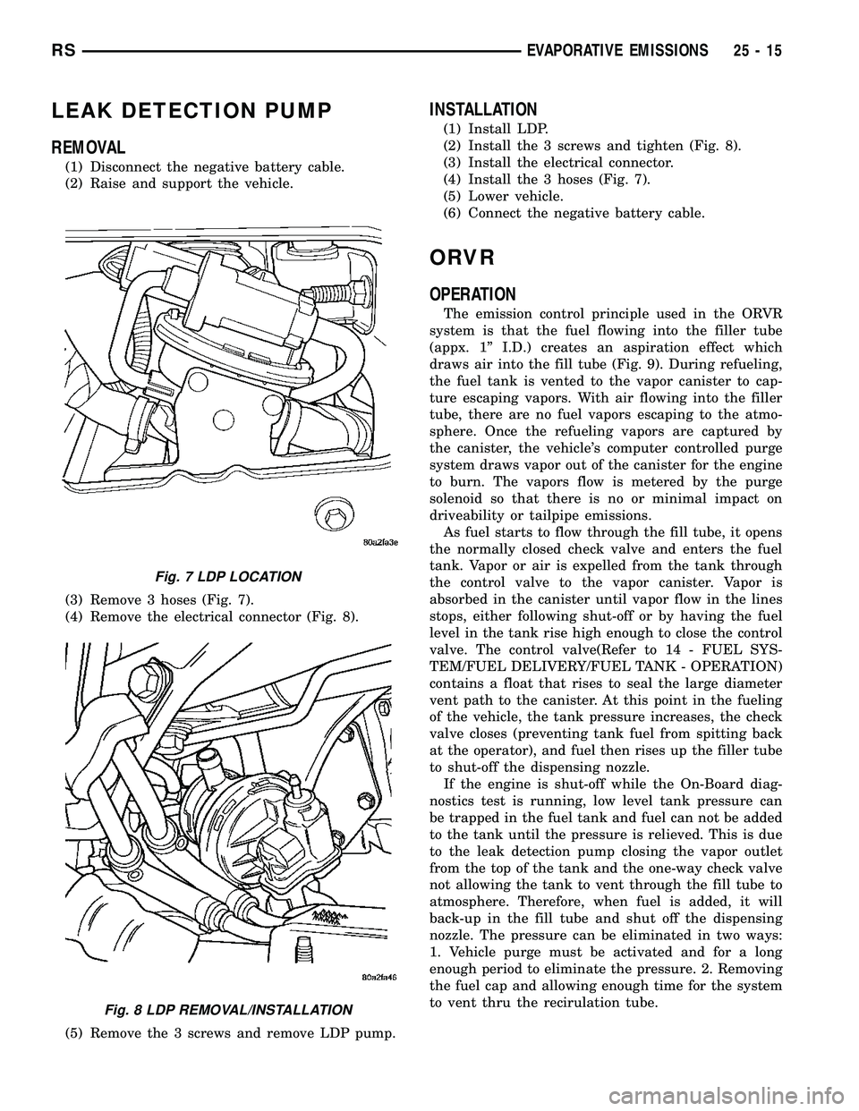
(3) Remove 3 hoses (Fig. 7).
(4) Remove the electrical connector (Fig. 8).
(5) Remove the 3 screws and remove LDP pump.
INSTALLATION
(1) Install LDP.
(2) Install the 3 screws and tighten (Fig. 8).
(3) Install the electrical connector.
(4) Install the 3 hoses (Fig. 7).
(5) Lower vehicle.
(6) Connect the negative battery cable.
ORVR
OPERATION
The emission control principle used in the ORVR
system is that the fuel flowing into the filler tube
(appx. 1º I.D.) creates an aspiration effect which
draws air into the fill tube (Fig. 9). During refueling,
the fuel tank is vented to the vapor canister to cap-
ture escaping vapors. With air flowing into the filler
tube, there are no fuel vapors escaping to the atmo-
sphere. Once the refueling vapors are captured by
the canister, the vehicle's computer controlled purge
system draws vapor out of the canister for the engine
to burn. The vapors flow is metered by the purge
solenoid so that there is no or minimal impact on
driveability or tailpipe emissions.
As fuel starts to flow through the fill tube, it opens
the normally closed check valve and enters the fuel
tank. Vapor or air is expelled from the tank through
the control valve to the vapor canister. Vapor is
absorbed in the canister until vapor flow in the lines
stops, either following shut-off or by having the fuel
level in the tank rise high enough to close the control
valve. The control valve(Refer to 14 - FUEL SYS-
TEM/FUEL DELIVERY/FUEL TANK - OPERATION)
contains a float that rises to seal the large diameter
vent path to the canister. At this point in the fueling
of the vehicle, the tank pressure increases, the check
valve closes (preventing tank fuel from spitting back
at the operator), and fuel then rises up the filler tube
to shut-off the dispensing nozzle.
If the engine is shut-off while the On-Board diag-
nostics test is running, low level tank pressure can
be trapped in the fuel tank and fuel can not be added
to the tank until the pressure is relieved. This is due
to the leak detection pump closing the vapor outlet
from the top of the tank and the one-way check valve
not allowing the tank to vent through the fill tube to
atmosphere. Therefore, when fuel is added, it will
back-up in the fill tube and shut off the dispensing
nozzle. The pressure can be eliminated in two ways:
1. Vehicle purge must be activated and for a long
enough period to eliminate the pressure. 2. Removing
the fuel cap and allowing enough time for the system
to vent thru the recirulation tube.
Fig. 7 LDP LOCATION
Fig. 8 LDP REMOVAL/INSTALLATION
RSEVAPORATIVE EMISSIONS25-15
Page 2300 of 2339
Alternate Good Trip
Alternate Good Trips are used in place of Global
Good Trips for Comprehensive Components and
Major Monitors. If the Task Manager cannot run a
Global Good Trip because a component fault is stop-
ping the monitor from running, it will attempt to
count an Alternate Good Trip.
The Task Manager counts an Alternate Good Trip
for Comprehensive components when the following
conditions are met:
²Two minutes of engine run time, idle or driving
²No other faults occur
The Task Manager counts an Alternate Good Trip
for a Major Monitor when the monitor runs and
passes. Only the Major Monitor that failed needs to
pass to count an Alternate Good Trip.
Warm-Up Cycles
Once the MIL has been extinguished by the Good
Trip Counter, the PCM automatically switches to a
Warm-Up Cycle Counter that can be viewed on the
scan tool. Warm-Up Cycles are used to erase DTCs
and Freeze Frames. Forty Warm-Up cycles must
occur in order for the PCM to self-erase a DTC and
Freeze Frame. A Warm-Up Cycle is defined as fol-
lows:
²Engine coolant temperature must start below
and rise above 160É F
²Engine coolant temperature must rise by 40É F
²No further faults occur
Freeze Frame Data Storage
Once a failure occurs, the Task Manager records
several engine operating conditions and stores it in a
Freeze Frame. The Freeze Frame is considered one
frame of information taken by an on-board data
recorder. When a fault occurs, the PCM stores the
input data from various sensors so that technicians
can determine under what vehicle operating condi-
tions the failure occurred.
The data stored in Freeze Frame is usually
recorded when a system fails the first time for two
trip faults. Freeze Frame data will only be overwrit-
ten by a different fault with a higher priority.
CAUTION: Erasing DTCs, either with the scan tool;
or by disconnecting the battery, also clears all
Freeze Frame data.
Similar Conditions Window
The Similar Conditions Window displays informa-
tion about engine operation during a monitor. Abso-
lute MAP (engine load) and Engine RPM are stored
in this window when a failure occurs. There are two
different Similar conditions Windows: Fuel System
and Misfire.FUEL SYSTEM
²Fuel System Similar Conditions WindowÐ
An indicator that 'Absolute MAP When Fuel Sys Fail'
and 'RPM When Fuel Sys Failed' are all in the same
range when the failure occurred. Indicated by switch-
ing from 'NO' to 'YES'.
²Absolute MAP When Fuel Sys FailÐ The
stored MAP reading at the time of failure. Informs
the user at what engine load the failure occurred.
²Absolute MAPÐ A live reading of engine load
to aid the user in accessing the Similar Conditions
Window.
²RPM When Fuel Sys FailÐ The stored RPM
reading at the time of failure. Informs the user at
what engine RPM the failure occurred.
²Engine RPMÐ A live reading of engine RPM
to aid the user in accessing the Similar Conditions
Window.
²Adaptive Memory FactorÐ The PCM utilizes
both Short Term Compensation and Long Term Adap-
tive to calculate the Adaptive Memory Factor for
total fuel correction.
²Upstream O2S VoltsÐ A live reading of the
Oxygen Sensor to indicate its performance. For
example, stuck lean, stuck rich, etc.
²SCW Time in Window (Similar Conditions
Window Time in Window)Ð A timer used by the
PCM that indicates that, after all Similar Conditions
have been met, if there has been enough good engine
running time in the SCW without failure detected.
This timer is used to increment a Good Trip.
²Fuel System Good Trip CounterÐATrip
Counter used to turn OFF the MIL for Fuel System
DTCs. To increment a Fuel System Good Trip, the
engine must be in the Similar Conditions Window,
Adaptive Memory Factor must be less than cali-
brated threshold and the Adaptive Memory Factor
must stay below that threshold for a calibrated
amount of time.
²Test Done This TripÐ Indicates that the
monitor has already been run and completed during
the current trip.
MISFIRE
²Same Misfire Warm-Up StateÐ Indicates if
the misfire occurred when the engine was warmed up
(above 160É F).
²In Similar Misfire WindowÐ An indicator
that 'Absolute MAP When Misfire Occurred' and
'RPM When Misfire Occurred' are all in the same
range when the failure occurred. Indicated by switch-
ing from 'NO' to 'YES'.
²Absolute MAP When Misfire OccurredÐ
The stored MAP reading at the time of failure.
Informs the user at what engine load the failure
occurred.
RSON-BOARD DIAGNOSTICS25-27
TASK MANAGER (Continued)
Page 2301 of 2339
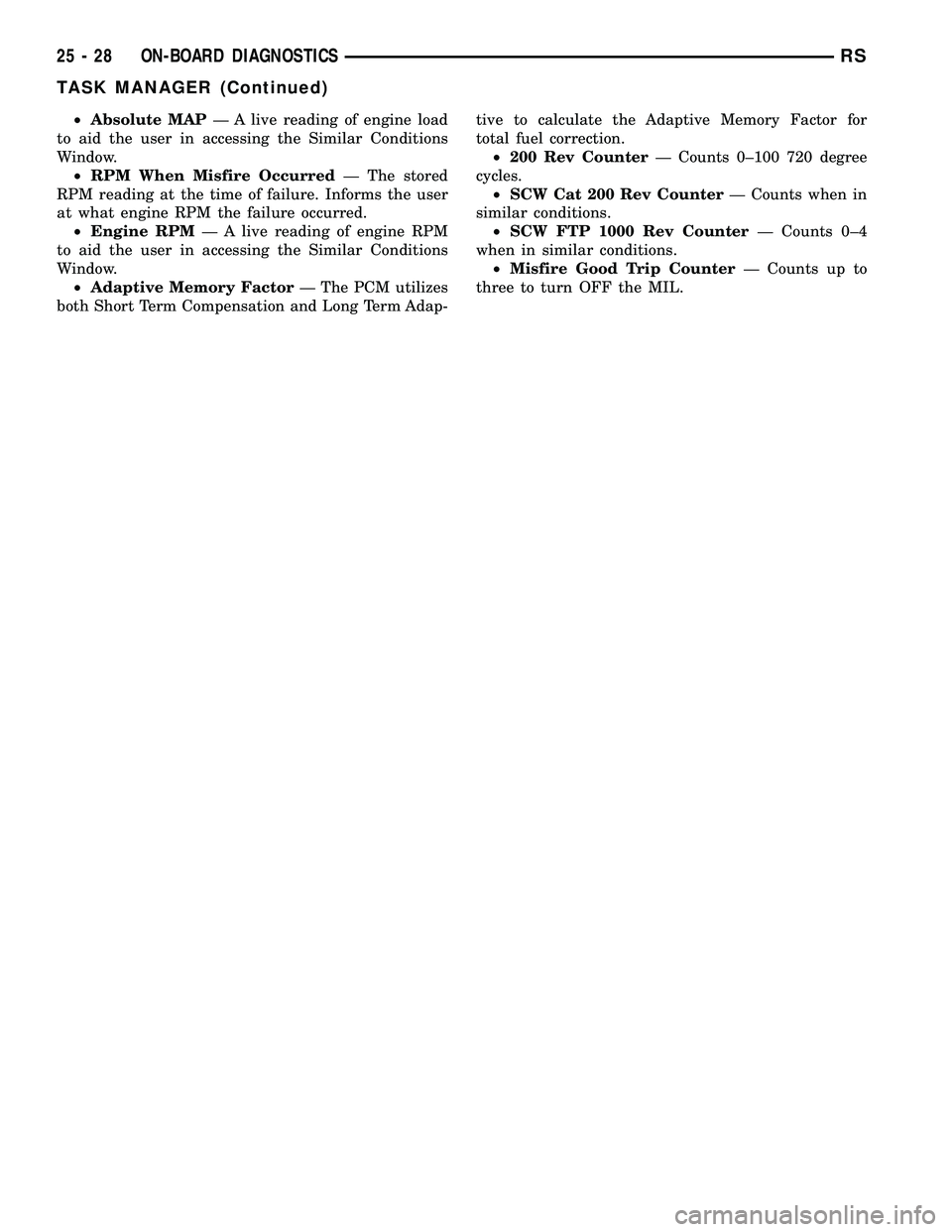
²Absolute MAPÐ A live reading of engine load
to aid the user in accessing the Similar Conditions
Window.
²RPM When Misfire OccurredÐ The stored
RPM reading at the time of failure. Informs the user
at what engine RPM the failure occurred.
²Engine RPMÐ A live reading of engine RPM
to aid the user in accessing the Similar Conditions
Window.
²Adaptive Memory FactorÐ The PCM utilizes
both Short Term Compensation and Long Term Adap-tive to calculate the Adaptive Memory Factor for
total fuel correction.
²200 Rev CounterÐ Counts 0±100 720 degree
cycles.
²SCW Cat 200 Rev CounterÐ Counts when in
similar conditions.
²SCW FTP 1000 Rev CounterÐ Counts 0±4
when in similar conditions.
²Misfire Good Trip CounterÐ Counts up to
three to turn OFF the MIL.
25 - 28 ON-BOARD DIAGNOSTICSRS
TASK MANAGER (Continued)
Page 2302 of 2339
INDEX
ABS FASTENER TORQUE,SPECIFICATIONS ...................... 5-91
ABSORBER - DESCRIPTION, SHOCK .......2-36
ABSORBER - INSTALLATION, SHOCK ......2-38
ABSORBER - OPERATION, SHOCK ........2-36
ABSORBER - REMOVAL, SHOCK ..........2-36
ABSORBER (UPPER BUSHING) - ASSEMBLY, SHOCK .................... 2-37
ABSORBER (UPPER BUSHING) - DISASSEMBLY, SHOCK .................2-37
A/C CLUTCH BREAK-IN, STANDARD PROCEDURE ........................ 24-15
A/C COMPRESSOR CLUTCH COIL, DIAGNOSIS AND TESTING .............24-14
A/C COMPRESSOR CLUTCH RELAY - DESCRIPTION ....................... 24-18
A/C COMPRESSOR CLUTCH RELAY - INSTALLATION ....................... 24-19
A/C COMPRESSOR CLUTCH RELAY - OPERATION ......................... 24-18
A/C COMPRESSOR CLUTCH RELAY - REMOVAL .......................... 24-19
A/C COMPRESSOR CLUTCH/COIL - DESCRIPTION ....................... 24-13
A/C COMPRESSOR CLUTCH/COIL - OPERATION ......................... 24-13
A/C COMPRESSOR, DESCRIPTION .......24-72
A/C COMPRESSOR, INSTALLATION .......24-74
A/C COMPRESSOR MOUNTING BRACKET, 2.4L ENGINE ...........24-74,24-75
A/C COMPRESSOR NOISE DIAGNOSIS, DIAGNOSIS AND TESTING .............24-72
A/C COMPRESSOR, OPERATION .........24-72
A/C COMPRESSOR, REMOVAL ..........24-73
A/C CONDENSER - DESCRIPTION ........24-75
A/C CONDENSER - OPERATION ..........24-75
A/C COOL DOWN TEST, DIAGNOSIS AND TESTING ............................ 24-6
A/C DISCHARGE LINE - INSTALLATION . . . 24-80
A/C DISCHARGE LINE - REMOVAL .......24-79
A/C EVAPORATOR - DESCRIPTION . . 24-80,24-98
A/C EVAPORATOR - INSTALLATION ......24-81
A/C EVAPORATOR - OPERATION ....24-80,24-98
A/C EVAPORATOR - REMOVAL ..........24-81
A/C EVAPORATOR, INSTALLATION - REAR ............................. 24-100
A/C EVAPORATOR LINE EXTENSION, INSTALLATION - REAR ...............24-100
A/C EVAPORATOR LINE EXTENSION, REMOVAL - REAR .................... 24-99
A/C EVAPORATOR, REMOVAL - REAR .....24-98
A/C EXPANSION VALVE - DESCRIPTION . . 24-100
A/C EXPANSION VALVE - OPERATION ....24-100
A/C EXPANSION VALVE, DIAGNOSIS AND TESTING - FRONT .................... 24-82
A/C EXPANSION VALVE, DIAGNOSIS AND TESTING - REAR .................... 24-101
A/C HEATER CONTROL - DESCRIPTION . . . 24-19
A/C PERFORMANCE TEST, DIAGNOSIS AND TESTING ........................ 24-7
A/C PRESSURE TRANSDUCER - DESCRIPTION ....................... 24-20
A/C PRESSURE TRANSDUCER - OPERATION ......................... 24-20
A/C PRESSURE TRANSDUCER, DIAGNOSIS AND TESTING .............24-21
A/C SYSTEM - CAUTION ...............24-66
A/C SYSTEM, SPECIFICATIONS ..........24-11
A/C SYSTEM, WARNING ...............24-66
ACCELERATOR PEDAL - INSTALLATION . . . 14-28
ACCELERATOR PEDAL - REMOVAL .......14-28
ACCESSORY DRIVE BELT - DIAGNOSIS AND TESTING .........................7-7
ACCESSORY DRIVE BELT TENSION, SPECIFICATIONS .......................7-5
ACCUMULATOR - DESCRIPTION . . . 21-218,21-73
ACCUMULATOR - OPERATION ....21-218,21-73
A/C-HEATER CONTROL - DESCRIPTION . . . 24-33
A/C-HEATER CONTROL - INSTALLATION . . . 24-34
A/C-HEATER CONTROL - OPERATION .....24-33
A/C-HEATER CONTROL - REMOVAL ......24-33
A/C-HEATER CONTROL CALIBRATION, STANDARD PROCEDURE ...............24-19
ACTUATOR - DESCRIPTION, BLEND DOOR ........................ 24-22,24-34
ACTUATOR - DESCRIPTION, ENGAGE ......8N-9
ACTUATOR - DESCRIPTION, LATCH ......8N-13 ACTUATOR - DESCRIPTION, MODE
DOOR ............................. 24-29
ACTUATOR - DESCRIPTION, RECIRCULATION DOOR ................24-31
ACTUATOR - INSTALLATION, BLEND DOOR ........................ 24-22,24-35
ACTUATOR - INSTALLATION, ENGAGE ....8N-10
ACTUATOR - INSTALLATION, INSIDE HANDLE ............................ 23-27
ACTUATOR - INSTALLATION, LATCH .....8N-14
ACTUATOR - INSTALLATION, MODE DOOR ............................. 24-30
ACTUATOR - INSTALLATION, RECIRCULATION DOOR ................24-32
ACTUATOR - OPERATION, BLEND DOOR . . 24-22, 24-35
ACTUATOR - OPERATION, ENGAGE .......8N-9
ACTUATOR - OPERATION, LATCH ........8N-13
ACTUATOR - OPERATION, MODE DOOR . . . 24-29
ACTUATOR - OPERATION, RECIRCULATION DOOR ................24-31
ACTUATOR - REAR - DESCRIPTION, MODE DOOR ........................ 24-39
ACTUATOR - REAR - INSTALLATION, MODE DOOR ........................ 24-40
ACTUATOR - REAR - OPERATION, MODE DOOR ............................. 24-39
ACTUATOR - REAR - REMOVAL, MODE DOOR ............................. 24-39
ACTUATOR - REMOVAL, BLEND DOOR . . . 24-22, 24-35
ACTUATOR - REMOVAL, ENGAGE ..........8N-9
ACTUATOR - REMOVAL, INSIDE HANDLE . . 23-27
ACTUATOR - REMOVAL, LATCH .........8N-13
ACTUATOR - REMOVAL, MODE DOOR ....24-29
ACTUATOR - REMOVAL, RECIRCULATION DOOR ............................. 24-32
ADAPTER - INSTALLATION, FRONT DISC BRAKE CALIPER ...................... 5-31
ADAPTER - INSTALLATION, OIL FILTER . . . 9-142
ADAPTER - REMOVAL, FRONT DISC BRAKE CALIPER ...................... 5-31
ADAPTER - REMOVAL, OIL FILTER .......9-142
ADAPTIVE MEMORIES, OPERATION - FUEL CORRECTION OR ................14-24
ADDING ADDITIONAL COOLANT - STANDARD PROCEDURE .................7-4
ADDITIONAL COOLANT - STANDARD PROCEDURE, ADDING ...................7-4
ADHESIVE ATTACHED - INSTALLATION, EXTERIOR NAME PLATES ..............23-51
ADHESIVE ATTACHED - REMOVAL, EXTERIOR NAME PLATES ..............23-51
ADHESIVE LOCATIONS - FOLD-IN-FLOOR ONLY - SPECIFICATIONS,
STRUCTURAL ...................... 23-228
ADHESIVE LOCATIONS - SPECIFICATIONS, STRUCTURAL ........23-218
ADJUSTABLE - INSTALLATION, PEDALS ....5-43
ADJUSTABLE - REMOVAL, PEDALS .......5-40
ADJUSTABLE PEDALS SWITCH - INSTALLATION ........................ 5-11
ADJUSTABLE PEDALS SWITCH - REMOVAL ........................... 5-11
ADJUSTE R-BOR C-PILLAR -
INSTALLATION, SEAT BELT HEIGHT ......8O-38
ADJUSTE R-BOR C-PILLAR -
REMOVAL, SEAT BELT HEIGHT ..........8O-38
ADJUSTER - DIAGNOSIS AND TESTING, DRUM BRAKE AUTOMATIC ..............5-14
ADJUSTER - INSTALLATION, FRONT SEAT TRACK MANUAL ...............23-126
ADJUSTER - INSTALLATION, FRONT SEAT TRACK POWER ................23-124
ADJUSTER - REMOVAL, FRONT SEAT TRACK MANUAL .................... 23-125
ADJUSTER - REMOVAL, FRONT SEAT TRACK POWER ..................... 23-124
ADJUSTER KNOB - INSTALLATION, SEAT BELT HEIGHT ....................... 8O-38
ADJUSTER KNOB - REMOVAL, SEAT BELT HEIGHT ....................... 8O-38
ADJUSTER NOISE DIAGNOSIS - DIAGNOSIS AND TESTING, HYDRAULIC
LASH ............................... 9-34
ADJUSTER TENSION RELEASE - STANDARD PROCEDURE, PARKING
BRAKE AUTOMATIC .................... 5-63ADJUSTER TENSION RESET -
STANDARD PROCEDURE, PARKING
BRAKE AUTOMATIC .................... 5-64
ADJUSTER/MANUAL - OCS - INSTALLATION, FRONT SEAT TRACK ....23-128
ADJUSTER/MANUAL - OCS - REMOVAL, FRONT SEAT TRACK .................23-126
ADJUSTER/POWER - OCS - INSTALLATION, FRONT SEAT TRACK ....23-125
ADJUSTER/POWER - OCS - REMOVAL, FRONT SEAT TRACK .................23-124
ADJUSTERS - INSTALLATION, HYDRAULIC LASH ..................... 9-35
ADJUSTERS - REMOVAL, HYDRAULIC LASH ............................... 9-35
AERATION - DIAGNOSIS AND TESTING, COOLING SYSTEM .....................7-4
AFTER AN AIRBAG DEPLOYMENT - STANDARD PROCEDURE, SERVICE .......8O-7
AIR CLEANER ELEMENT - INSTALLATION . 9-101, 9-24
AIR CLEANER ELEMENT - REMOVAL . 9-101,9-24
AIR CLEANER HOUSING - INSTALLATION . 9-102, 9-25
AIR CLEANER HOUSING - REMOVAL . 9-101,9-25
AIR CONDITIONER, DESCRIPTION - HEATER ............................. 24-1
AIR CONDITIONER, OPERATION - HEATER ............................. 24-4
AIR CONTROL MOTOR - DESCRIPTION, IDLE ............................... 14-33
AIR CONTROL MOTOR - INSTALLATION, IDLE ............................... 14-33
AIR CONTROL MOTOR - OPERATION, IDLE ............................... 14-33
AIR CONTROL MOTOR - REMOVAL, IDLE . . 14-33
AIR EXHAUSTER - DESCRIPTION, REAR QUARTER PANEL/FENDER ..............23-59
AIR EXHAUSTER - INSTALLATION, REAR QUARTER PANEL/FENDER ..............23-60
AIR EXHAUSTER - REMOVAL, REAR QUARTER PANEL/FENDER ..............23-59
AIR FILTER - DESCRIPTION ............24-42
AIR FILTER - INSTALLATION ............24-43
AIR FILTER - REMOVAL ...............24-42
AIR GAP, SPECIFICATIONS - WHEEL SPEED SENSOR ....................... 5-91
AIR INTAKE PIPE - INSTALLATION ......24-115
AIR INTAKE PIPE - REMOVAL ..........24-115
AIR OUTLETS - DESCRIPTION .....24-43,24-56
AIR OUTLETS - INSTALLATION ..........24-56
AIR OUTLETS - REMOVAL .............24-56
AIR PRESSURE TESTS - DIAGNOSIS AND TESTING, CLUTCH ...........21-153,21-8
AIR TEMPERATURE SENSOR - DESCRIPTION, INLET .................14-34
AIRBAG - DESCRIPTION, CURTAIN .......8O-12
AIRBAG - DESCRIPTION, DRIVER ........8O-16
AIRBAG - DESCRIPTION, KNEE BLOCKER . 8O-22
AIRBAG - DESCRIPTION, PASSENGER ....8O-30
AIRBAG - INSTALLATION, CURTAIN ......8O-16
AIRBAG - INSTALLATION, DRIVER .......8O-18
AIRBAG - INSTALLATION, KNEE BLOCKER .......................... 8O-23
AIRBAG - INSTALLATION, PASSENGER . . . 8O-32
AIRBAG - OPERATION, CURTAIN ........8O-13
AIRBAG - OPERATION, DRIVER .........8O-16
AIRBAG - OPERATION, KNEE BLOCKER . . . 8O-22
AIRBAG - OPERATION, PASSENGER ......8O-30
AIRBAG - REMOVAL, CURTAIN ..........8O-14
AIRBAG - REMOVAL, DRIVER ...........8O-17
AIRBAG - REMOVAL, KNEE BLOCKER ....8O-23
AIRBAG - REMOVAL, PASSENGER .......8O-30
AIRBAG DEPLOYMENT - STANDARD PROCEDURE, SERVICE AFTER AN ........8O-7
AIRBAG DISABLED INDICATOR - DESCRIPTION, PASSENGER ............8O-33
AIRBAG DISABLED INDICATOR - INSTALLATION, PASSENGER ...........8O-34
AIRBAG DISABLED INDICATOR - OPERATION, PASSENGER ..............8O-33
AIRBAG DISABLED INDICATOR - REMOVAL, PASSENGER ...............8O-34
AIRBAG SYSTEM - DIAGNOSIS AND TESTING ............................ 8O-6
AIRBAGS - STANDARD PROCEDURE, HANDLING .......................... 8O-6
RS INDEX1
Description Group-Page Description Group-Page Description Group-Page
Page 2305 of 2339
BENCH SEAT RISER - 50/50 SPLIT -INSTALLATION ...................... 23-145
BENCH SEAT RISER - 50/50 SPLIT - REMOVAL ......................... 23-145
BENCH SEAT RISER - SECOND ROW - INSTALLATION ...................... 23-145
BENCH SEAT RISER - SECOND ROW - REMOVAL ......................... 23-145
BENCH SEAT RISER - THIRD ROW - INSTALLATION ...................... 23-145
BENCH SEAT RISER - THIRD ROW - REMOVAL ......................... 23-145
BENCH SEAT TRACK - INSTALLATION . . . 23-148
BENCH SEAT TRACK - REMOVAL .......23-148
BEZEL - INSTALLATION, CLUSTER .......23-65
BEZEL - INSTALLATION, INSTRUMENT PANEL CENTER ...................... 23-72
BEZEL - INSTALLATION, SLIDING DOOR STOP BUMPER ...................... 23-25
BEZEL - REMOVAL, CLUSTER ...........23-65
BEZEL - REMOVAL, INSTRUMENT PANEL CENTER ............................ 23-71
BEZEL - REMOVAL, SLIDING DOOR STOP BUMPER ...................... 23-25
BEZEL OUTLETS, INSTALLATION - FRONT CENTER ...................... 24-45
BEZEL OUTLETS, REMOVAL - FRONT CENTER ............................ 24-44
BIN - INSTALLATION, UNDER SEAT STORAGE .......................... 23-149
BIN - REMOVAL, UNDER SEAT STORAGE . 23-149
BIN GUIDE - INSTALLATION, UNDER SEAT STORAGE ..................... 23-150
BIN GUIDE - REMOVAL, UNDER SEAT STORAGE .......................... 23-150
BIN LOCK/LATCH - INSTALLATION, UNDER SEAT STORAGE ...............23-150
BIN LOCK/LATCH - REMOVAL, UNDER SEAT STORAGE ..................... 23-150
BLADDER & PRESSURE SENSOR - DESCRIPTION, SEAT WEIGHT ...........8O-43
BLADDER & PRESSURE SENSOR - OPERATION, SEAT WEIGHT ............8O-44
BLADES - CLEANING, WIPER ...........8R-13
BLADES - INSTALLATION, WIPER ........8R-13
BLADES - REMOVAL, WIPER ...........8R-13
BLEEDING - STANDARD PROCEDURE, ANTILOCK BRAKE SYSTEM ..............5-90
BLEEDING - STANDARD PROCEDURE, BASE BRAKE ..........................5-8
BLEEDING - STANDARD PROCEDURE, MASTER CYLINDER ................... 5-36
BLEND DOOR ACTUATOR - DESCRIPTION .................. 24-22,24-34
BLEND DOOR ACTUATOR - INSTALLATION .................. 24-22,24-35
BLEND DOOR ACTUATOR - OPERATION . . 24-22, 24-35
BLEND DOOR ACTUATOR - REMOVAL ....24-22,
24-35
BLOCK - CLEANING, ENGINE .......9-115,9-37
BLOCK - DESCRIPTION, BLOWER MOTOR RESISTOR ..............24-24,24-37
BLOCK - DESCRIPTION, ENGINE .....9-115,9-36
BLOCK - DESCRIPTION, NON-ABS JUNCTION ........................... 5-33
BLOCK - INSPECTION, ENGINE ......9-115,9-37
BLOCK - INSTALLATION, NON-ABS JUNCTION ........................... 5-34
BLOCK - OPERATION, BLOWER MOTOR RESISTOR ..................... 24-24,24-37
BLOCK - OPERATION, NON-ABS JUNCTION ........................... 5-33
BLOCK - REMOVAL, NON-ABS JUNCTION . . 5-34
BLOCK, DIAGNOSIS AND TESTING - FRONT BLOWER MOTOR RESISTOR ......24-25
BLOCK, DIAGNOSIS AND TESTING - REAR BLOWER MOTOR RESISTOR ......24-38
BLOCK HEATER - DESCRIPTION, ENGINE . . . 7-20
BLOCK HEATER - INSTALLATION, ENGINE ............................. 7-21
BLOCK HEATER - OPERATION, ENGINE ....7-20
BLOCK HEATER - REMOVAL, ENGINE ......7-21
BLOCK HEATER TESTING - DIAGNOSIS AND TESTING, ENGINE .................7-21
BLOCKER AIRBAG - DESCRIPTION, KNEE . 8O-22
BLOCKER AIRBAG - INSTALLATION, KNEE .............................. 8O-23BLOCKER AIRBAG - OPERATION, KNEE . . . 8O-22
BLOCKER AIRBAG - REMOVAL, KNEE
....8O-23
BLOCKER- INFLATABLE KNEE - INSTALLATION ....................... 23-75
BLOCKER- INFLATABLE KNEE - REMOVAL .......................... 23-75
BLOCKER LATCH - INSTALLATION, FUEL FILL DOOR ......................... 23-53
BLOCKER LATCH - REMOVAL, FUEL FILL DOOR ............................. 23-53
BLOCKER LATCH STRIKER - INSTALLATION, FUEL FILL DOOR ........23-53
BLOCKER LATCH STRIKER - REMOVAL, FUEL FILL DOOR ..................... 23-53
BLOCKER LOCKOUT LINK - INSTALLATION, FUEL FILL DOOR ........23-54
BLOCKER LOCKOUT LINK - REMOVAL, FUEL FILL DOOR ..................... 23-54
BLOWER MOTOR - DESCRIPTION . . 24-45,24-57
BLOWER MOTOR - DESCRIPTION, POWER MODULE .................... 24-30
BLOWER MOTOR - DESCRIPTION, POWER MODULE - REAR ..............24-40
BLOWER MOTOR - INSTALLATION, POWER MODULE .................... 24-31
BLOWER MOTOR - INSTALLATION, POWER MODULE - REAR ..............24-41
BLOWER MOTOR - OPERATION ....24-45,24-57
BLOWER MOTOR - OPERATION, POWER MODULE ........................... 24-30
BLOWER MOTOR - OPERATION, POWER MODULE - REAR ..................... 24-40
BLOWER MOTOR - REMOVAL, POWER MODULE ........................... 24-30
BLOWER MOTOR - REMOVAL, POWER MODULE - REAR ..................... 24-41
BLOWER MOTOR, DIAGNOSIS AND TESTING - FRONT .................... 24-46
BLOWER MOTOR, DIAGNOSIS AND TESTING - REAR ..................... 24-58
BLOWER MOTOR RELAY - DESCRIPTION . 24-23, 24-36
BLOWER MOTOR RELAY - INSTALLATION .................. 24-24,24-37
BLOWER MOTOR RELAY - OPERATION . . . 24-23, 24-36
BLOWER MOTOR RELAY - REMOVAL ....24-24,
24-37
BLOWER MOTOR RESISTOR BLOCK - DESCRIPTION .................. 24-24,24-37
BLOWER MOTOR RESISTOR BLOCK - OPERATION .................... 24-24,24-37
BLOWER MOTOR RESISTOR BLOCK, DIAGNOSIS AND TESTING - FRONT ......24-25
BLOWER MOTOR RESISTOR BLOCK, DIAGNOSIS AND TESTING - REAR .......24-38
BODY - ASSEMBLY, VALVE ......21-139,21-291
BODY - DESCRIPTION, THROTTLE .......14-39
BODY - DESCRIPTION, VALVE ....21-132,21-283
BODY - DISASSEMBLY, VALVE . . . 21-135,21-286
BODY - INSTALLATION, THROTTLE .......14-40
BODY - INSTALLATION, VALVE . . . 21-144,21-295
BODY - OPERATION, THROTTLE .........14-39
BODY - OPERATION, VALVE .....21-132,21-283
BODY - REMOVAL, THROTTLE ..........14-40
BODY - REMOVAL, VALVE .......21-133,21-284
BODY AND CABLE - DESCRIPTION, ANTENNA ........................... 8A-7
BODY AND CABLE - OPERATION, ANTENNA ........................... 8A-7
BODY AND CABLE, DIAGNOSIS AND TESTING - ANTENNA ................... 8A-8
BODY CONTROL MODULE - DESCRIPTION ........................ 8E-2
BODY CONTROL MODULE - INSTALLATION ........................ 8E-4
BODY CONTROL MODULE - OPERATION . . . 8E-3
BODY CONTROL MODULE - REMOVAL .....8E-4
BODY LUBRICATION, SPECIFICATIONS ....23-12
BODY OPENING DIMENSIONS - SPECIFICATIONS .................... 23-180
BODY PANEL REPAIR - STANDARD PROCEDURE, PLASTIC .................23-3
BODY SEALING LOCATIONS - FOLD-IN- FLOOR ONLY - SPECIFICATIONS ........23-209
BODY SEALING LOCATIONS - SPECIFICATIONS .................... 23-183
BODY SIDE - INSTALLATION ............23-44BODY SIDE - REMOVAL
...............23-44
BODY SIDE MOLDINGS - INSTALLATION . . 23-46
BODY SIDE MOLDINGS - REMOVAL ......23-45
BODY, SPECIAL TOOLS ................23-13
BOLSTER - INSTALLATION, QUARTER TRIM .............................. 23-95
BOLSTER - REMOVAL, QUARTER TRIM . . . 23-95
BOOSTER - DESCRIPTION, POWER BRAKE .............................. 5-45
BOOSTER - DIAGNOSIS AND TESTING, POWER BRAKE ....................... 5-46
BOOSTER - OPERATION, POWER BRAKE . . . 5-46
BOOT - INNER - INSTALLATION, CV ........3-7
BOOT - INNER - REMOVAL, CV ...........3-6
BOOT - OUTER - INSTALLATION, CV ......3-11
BOOT - OUTER - REMOVAL, CV ..........3-10
BORE FITTING - STANDARD PROCEDURE, PISTON TO CYLINDER ......9-44
BORE HONING - STANDARD PROCEDURE, CYLINDER ...........9-115,9-36
BOTTOM OF SEAT CUSHION PAN PANEL-THIRD ROW - FOLD-IN-FLOOR
- INSTALLATION .................... 23-152
BOTTOM OF SEAT CUSHION PAN PANEL-THIRD ROW - FOLD-IN-FLOOR
- REMOVAL ........................ 23-152
BOX - INSTALLATION, GLOVE ...........23-66
BOX - REMOVAL, GLOVE ..............23-66
BOX LAMP SWITCH - INSTALLATION, GLOVE ............................. 8L-22
BOX LAMP SWITCH - REMOVAL, GLOVE . . 8L-22
BOX LATCH - INSTALLATION, GLOVE .....23-66
BOX LATCH - REMOVAL, GLOVE .........23-66
BOX LATCH STRIKER - INSTALLATION, GLOVE ............................. 23-66
BOX LATCH STRIKER - REMOVAL, GLOVE ............................. 23-66
B-PILLAR - INSTALLATION, A-PILLAR- HEADER, OR ........................ 23-17
B-PILLAR - REMOVAL, A-PILLAR- HEADER, OR ........................ 23-17
B-PILLAR LOWER TRIM - INSTALLATION . . 23-80
B-PILLAR LOWER TRIM - REMOVAL .....23-79
B-PILLAR SWITCH - DESCRIPTION ......8N-52
B-PILLAR SWITCH - INSTALLATION ......8N-52
B-PILLAR SWITCH - OPERATION ........8N-52
B-PILLAR SWITCH - REMOVAL .........8N-52
B-PILLAR UPPER TRIM - INSTALLATION . . 23-80
B-PILLAR UPPER TRIM - REMOVAL ......23-80
BRACKET - DESCRIPTION, TRANSVERSE . . 8N-19
BRACKET - INSTALLATION, TRANSVERSE . 8N-19
BRACKET - OPERATION, TRANSVERSE . . . 8N-19
BRACKET - REMOVAL, TRANSVERSE .....8N-19
BRACKET, 2.4L ENGINE - A/C COMPRESSOR MOUNTING ........24-74,24-75
BRAKE - DESCRIPTION, CONTROLLER ANTILOCK ........................... 8E-4
BRAKE - INSTALLATION, CONTROLLER ANTILOCK ........................... 8E-6
BRAKE - INSTALLATION, LEVER - PARKING ............................ 5-76
BRAKE - INSTALLATION, SHOES - PARKING ............................ 5-84
BRAKE - INSTALLATION, SUPPORT PLATE - DRUM ....................... 5-61
BRAKE - OPERATION, CONTROLLER ANTILOCK ........................... 8E-5
BRAKE - REMOVAL, CONTROLLER ANTILOCK ........................... 8E-5
BRAKE - REMOVAL, LEVER - PARKING ....5-75
BRAKE - REMOVAL, SHOES - PARKING ....5-78
BRAKE - REMOVAL, SUPPORT PLATE - DRUM .............................. 5-61
BRAKE AUTOMATIC ADJUSTER - DIAGNOSIS AND TESTING, DRUM ........5-14
BRAKE AUTOMATIC ADJUSTER TENSION RELEASE - STANDARD PROCEDURE,
PARKING ............................ 5-63
BRAKE AUTOMATIC ADJUSTER TENSION RESET - STANDARD PROCEDURE,
PARKING ............................ 5-64
BRAKE BLEEDING - STANDARD PROCEDURE, BASE .....................5-8
BRAKE BOOSTER - DESCRIPTION, POWER ............................. 5-45
BRAKE BOOSTER - DIAGNOSIS AND TESTING, POWER ..................... 5-46
BRAKE BOOSTER - OPERATION, POWER . . . 5-46
4 INDEXRS
Description Group-Page Description Group-Page Description Group-Page
Page 2313 of 2339
ENGINE OIL PRESSURE - DIAGNOSISAND TESTING, CHECKING ...............9-53
ENGINE, SPECIAL TOOLS - 2.4L ..........9-21
ENGINE, SPECIAL TOOLS - 3.3/3.8L .......9-98
ENGINE, SPECIFICATIONS - 3.3/3.8L ......9-93
ENGINE SPEED SENSOR - DESCRIPTION . . 14-30
ENGINE SPEED SENSOR - OPERATION ....14-30
ENGINE, STANDARD PROCEDURE - HYDROSTATIC LOCKED .............9-10,9-87
ENGINES - DESCRIPTION, ENGINE OIL - DIESEL ..............................0-6
ENGINES - EXPORT - DESCRIPTION, DIESEL ............................. 0-21
ENGINES, INSTALLATION - 2.4L/3.3L/ 3.8L ............................... 24-77
ENGINES, INSTALLATION - 2.5L/2.8L DIESEL ............................ 24-78
ENGINES, REMOVAL - 2.4L/3.3L/3.8L .....24-76
ENGINES, REMOVAL - 2.5L/2.8L DIESEL . . 24-77
ENTRY MODULE - DESCRIPTION, SENTRY KEY REMOTE .................8Q-3
ENTRY MODULE - DIAGNOSIS AND TESTING, SENTRY KEY REMOTE .........8Q-5
ENTRY MODULE - INSTALLATION, SENTRY KEY REMOTE .................8Q-6
ENTRY MODULE - OPERATION, SENTRY KEY REMOTE ........................ 8Q-4
ENTRY MODULE - REMOVAL, SENTRY KEY REMOTE ........................ 8Q-6
ENTRY SYSTEM - DIAGNOSIS AND TESTING, SENTRY KEY REMOTE .........8Q-3
ENTRY TRANSMITTER, DIAGNOSIS AND TESTING - KEYLESS .................. 8N-24
ENTRY TRANSMITTER PROGRAMMING - STANDARD PROCEDURE, REMOTE
KEYLESS ........................... 8N-24
EQUIPMENT, STANDARD PROCEDURE - REFRIGERANT SYSTEM SERVICE ........24-69
ERASING TRANSMITTER CODES, STANDARD PROCEDURE ..............8M-12
EVACUATE, STANDARD PROCEDURE - REFRIGERANT SYSTEM ...............24-70
EVAP CANISTER - INSTALLATION, REAR . . 25-21
EVAP CANISTER - REMOVAL, REAR ......25-20
EVAPORATION CONTROL SYSTEM - OPERATION ......................... 25-11
EVAPORATOR - DESCRIPTION, A/C . 24-80,24-98
EVAPORATOR - INSTALLATION, A/C ......24-81
EVAPORATOR - OPERATION, A/C . . . 24-80,24-98
EVAPORATOR - REMOVAL, A/C ..........24-81
EVAPORATOR, INSTALLATION - REAR A/C............................... 24-100
EVAPORATOR LINE EXTENSION, INSTALLATION - REAR A/C ............24-100
EVAPORATOR LINE EXTENSION, REMOVAL - REAR A/C .................24-99
EVAPORATOR, REMOVAL - REAR A/C .....24-98
EVAPORATOR TEMPERATURE SENSOR - DESCRIPTION ....................... 24-26
EVAPORATOR TEMPERATURE SENSOR - OPERATION ......................... 24-27
EVAP/PURGE SOLENOID - DESCRIPTION . . 25-13
EVAP/PURGE SOLENOID - INSTALLATION . 25-13
EVAP/PURGE SOLENOID - OPERATION ....25-13
EVAP/PURGE SOLENOID - REMOVAL .....25-13
EXCESSIVE EXHAUST SYSTEM NOISE - DIAGNOSIS AND TESTING ..............11-2
EXHAUST MANIFOLD - CLEANING ........9-63
EXHAUST MANIFOLD - INSPECTION .......9-63
EXHAUST MANIFOLD - INSTALLATION .....9-63
EXHAUST MANIFOLD - LEFT - CLEANING . . 9-154
EXHAUST MANIFOLD - LEFT - INSPECTION ........................ 9-155
EXHAUST MANIFOLD - LEFT - INSTALLATION ....................... 9-155
EXHAUST MANIFOLD - LEFT - REMOVAL . . 9-154
EXHAUST MANIFOLD - REMOVAL .........9-63
EXHAUST MANIFOLD - RIGHT - CLEANING .......................... 9-153
EXHAUST MANIFOLD - RIGHT - INSPECTION ........................ 9-153
EXHAUST MANIFOLD - RIGHT - INSTALLATION ....................... 9-153
EXHAUST MANIFOLD - RIGHT - REMOVAL .......................... 9-152
EXHAUST SYSTEM - DESCRIPTION .......11-1
EXHAUST SYSTEM NOISE - DIAGNOSIS AND TESTING, EXCESSIVE ..............11-2EXHAUST SYSTEM RESTRICTION CHECK
- DIAGNOSIS AND TESTING .............11-2
EXHAUST SYSTEM, SPECIAL TOOLS ......11-4
EXHAUST TUBE - INSTALLATION .......24-116
EXHAUST TUBE - REMOVAL ...........24-116
EXHAUSTER - DESCRIPTION, REAR QUARTER PANEL/FENDER AIR ..........23-59
EXHAUSTER - INSTALLATION, REAR QUARTER PANEL/FENDER AIR ..........23-60
EXHAUSTER - REMOVAL, REAR QUARTER PANEL/FENDER AIR ..........23-59
EXPANSION VALVE - DESCRIPTION ......24-81
EXPANSION VALVE - DESCRIPTION, A/C . 24-100
EXPANSION VALVE - OPERATION ........24-81
EXPANSION VALVE - OPERATION, A/C . . . 24-100
EXPANSION VALVE, DIAGNOSIS AND TESTING - FRONT A/C .................24-82
EXPANSION VALVE, DIAGNOSIS AND TESTING - REAR A/C .................24-101
EXPORT - ANTENNA MODULE ..........8A-10
EXPORT - BRAKE ROTOR ...............5-60
EXPORT - DESCRIPTION ................5-63
EXPORT - DESCRIPTION ................0-13
EXPORT - DESCRIPTION ................2-10
EXPORT - DESCRIPTION, ANTENNA MODULE ........................... 8A-10
EXPORT - DESCRIPTION, DIESEL ENGINES ............................ 0-21
EXPORT - DESCRIPTION, DOOR CYLINDER LOCK SWITCH ...............8N-22
EXPORT - DESCRIPTION, POWER FOLDAWAY MIRROR SWITCH ..........8N-29
EXPORT - DESCRIPTION, QUARTER GLASS INTEGRAL ANTENNA ............8A-13
EXPORT - DOOR CYLINDER LOCK SWITCH ............................ 8N-22
EXPORT - INSTALLATION ...............5-68
EXPORT - INSTALLATION ...............2-11
EXPORT - INSTALLATION, HEADLAMP UNIT .............................. 8L-17
EXPORT - INSTALLATION, HOOD AJAR SWITCH ............................ 8Q-3
EXPORT - INSTALLATION, POWER FOLDAWAY MIRROR SWITCH ..........8N-30
EXPORT - OPERATION, ANTENNA MODULE ........................... 8A-10
EXPORT - OPERATION, DOOR CYLINDER LOCK SWITCH ....................... 8N-22
EXPORT - OPERATION, POWER FOLDAWAY MIRROR SWITCH ..........8N-29
EXPORT - OPERATION, QUARTER GLASS INTEGRAL ANTENNA .................. 8A-13
EXPORT - QUARTER GLASS INTEGRAL ANTENNA .......................... 8A-13
EXPORT - REMOVAL ................... 5-67
EXPORT - REMOVAL ................... 2-11
EXPORT - REMOVAL, HEADLAMP UNIT . . . 8L-17
EXPORT - REMOVAL, HOOD AJAR SWITCH ............................ 8Q-3
EXPORT - REMOVAL, POWER FOLDAWAY MIRROR SWITCH ..........8N-29
EXPORT - STANDARD PROCEDURE, FRONT FOG LAMP UNIT ALIGNMENT ......8L-9
EXPORT - STANDARD PROCEDURE, HEADLAMP UNIT ALIGNMENT ..........8L-15
EXTENSION, INSTALLATION - REAR A/C EVAPORATOR LINE .................. 24-100
EXTENSION, REMOVAL - REAR A/C EVAPORATOR LINE ................... 24-99
EXTENSION TRIM - INSTALLATION, A-PILLAR LOWER .................... 23-79
EXTENSION TRIM - REMOVAL, A-PILLAR LOWER ............................ 23-79
EXTERIOR - DESCRIPTION, LAMPS/ LIGHTING ........................... 8L-2
EXTERIOR - OPERATION, LAMPS/ LIGHTING ........................... 8L-2
EXTERIOR - WARNING, LAMPS/ LIGHTING ........................... 8L-3
EXTERIOR HANDLE - INSTALLATION .....23-22,
23-40
EXTERIOR HANDLE - REMOVAL ....23-21,23-40
EXTERIOR HANDLE SWITCH - DESCRIPTION ....................... 8N-10
EXTERIOR HANDLE SWITCH - INSTALLATION ...................... 8N-10
EXTERIOR HANDLE SWITCH - OPERATION ......................... 8N-10EXTERIOR HANDLE SWITCH - REMOVAL . . 8N-10
EXTERIOR LAMPS, SPECIFICATIONS
......8L-3
EXTERIOR NAME PLATES - ADHESIVE ATTACHED - INSTALLATION ............23-51
EXTERIOR NAME PLATES - ADHESIVE ATTACHED - REMOVAL ................23-51
EXTERIOR NAME PLATES - TAPE ATTACHED - INSTALLATION ............23-51
EXTERIOR NAME PLATES - TAPE ATTACHED - REMOVAL ................23-51
FACTOR SETTING - STANDARD PROCEDURE, PINION .................8E-15
FAILED PARK SWITCH - DIAGNOSIS AND TESTING ............................ 8R-2
FAN - DESCRIPTION, RADIATOR ..........7-29
FAN - INSTALLATION, RADIATOR .........7-30
FAN - OPERATION, RADIATOR ...........7-29
FAN - REMOVAL, RADIATOR .............7-30
FAN MOTOR - DIAGNOSIS AND TESTING, RADIATOR ................... 7-30
FAN RELAY - DESCRIPTION, RADIATOR ....7-31
FAN RELAY - INSTALLATION, RADIATOR . . . 7-31
FAN RELAY - OPERATION, RADIATOR ......7-31
FAN RELAY - REMOVAL, RADIATOR .......7-31
FASCIA - INSTALLATION, FRONT .........13-1
FASCIA - INSTALLATION, REAR ..........13-4
FASCIA - REMOVAL, FRONT .............13-1
FASCIA - REMOVAL, REAR ..............13-4
FASCIA - SCUFF PAD - INSTALLATION, REAR ............................... 13-5
FASCIA - SCUFF PAD - REMOVAL, REAR . . . 13-5
FASTENER TORQUE, SPECIFICATIONS - ABS ................................ 5-91
FASTENER TORQUE, SPECIFICATIONS - BRAKE ...............................5-9
FASTENER TORQUE, SPECIFICATIONS - COLUMN ........................... 19-17
FASTENER TORQUE, SPECIFICATIONS - FRONT SUSPENSION ...................2-3
FASTENER TORQUE, SPECIFICATIONS - POWER STEERING .................... 19-9
FASTENER TORQUE, SPECIFICATIONS - REAR SUSPENSION ................... 2-28
FEED CIRCUIT RESISTANCE TEST - DIAGNOSIS AND TESTING ..............8F-35
FEED CIRCUIT TEST - DIAGNOSIS AND TESTING ........................... 8F-36
FENDER - INSTALLATION, FRONT ........23-52
FENDER - REMOVAL, FRONT ...........23-51
FFV REPLACEMENT PARTS - DESCRIPTION ........................ 14-2
FILL - DIAGNOSIS AND TESTING, VEHICLE DOES NOT .................. 25-17
FILL DOOR - INSTALLATION, FUEL .......23-52
FILL DOOR - REMOVAL, FUEL ..........23-52
FILL DOOR BLOCKER LATCH - INSTALLATION, FUEL .................23-53
FILL DOOR BLOCKER LATCH - REMOVAL, FUEL ..................... 23-53
FILL DOOR BLOCKER LATCH STRIKER - INSTALLATION, FUEL .................23-53
FILL DOOR BLOCKER LATCH STRIKER - REMOVAL, FUEL ..................... 23-53
FILL DOOR BLOCKER LOCKOUT LINK - INSTALLATION, FUEL .................23-54
FILL DOOR BLOCKER LOCKOUT LINK - REMOVAL, FUEL ..................... 23-54
FILL/CHECK LOCATIONS - DESCRIPTION, FLUID ...............................0-7
FILLER CAP - DESCRIPTION, FUEL .......25-13
FILLER CAP - OPERATION, FUEL ........25-13
FILLER NECK SEAL - DIAGNOSIS AND TESTING, RADIATOR CAP TO ............7-28
FILLER TUBE - INSTALLATION, FUEL TANK .............................. 14-17
FILLER TUBE - REMOVAL, FUEL TANK ....14-16
FILLING - STANDARD PROCEDURE, COOLING SYSTEM .....................7-4
FILLING, STANDARD PROCEDURE - REAR HEATER CORE .................24-102
FILTER - DESCRIPTION, AIR ............24-42
FILTER - DESCRIPTION, OIL .............9-54
FILTER - INSTALLATION, AIR ...........24-43
FILTER - INSTALLATION, INLET ..........14-17
FILTER - INSTALLATION, OIL .......9-141,9-54
FILTER - REMOVAL, AIR ...............24-42
FILTER - REMOVAL, INLET .............14-17
FILTER - REMOVAL, OIL ...........9-141,9-54
12 INDEXRS
Description Group-Page Description Group-Page Description Group-Page