2005 CHRYSLER CARAVAN engine oil
[x] Cancel search: engine oilPage 1335 of 2339
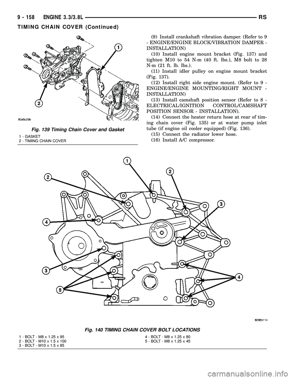
(9) Install crankshaft vibration damper. (Refer to 9
- ENGINE/ENGINE BLOCK/VIBRATION DAMPER -
INSTALLATION)
(10) Install engine mount bracket (Fig. 137) and
tighten M10 to 54 N´m (40 ft. lbs.), M8 bolt to 28
N´m (21 ft. lb. lbs.).
(11) Install idler pulley on engine mount bracket
(Fig. 137).
(12) Install right side engine mount. (Refer to 9 -
ENGINE/ENGINE MOUNTING/RIGHT MOUNT -
INSTALLATION)
(13) Install camshaft position sensor (Refer to 8 -
ELECTRICAL/IGNITION CONTROL/CAMSHAFT
POSITION SENSOR - INSTALLATION).
(14) Connect the heater return hose at rear of tim-
ing chain cover (Fig. 135) or at water pump inlet
tube (if engine oil cooler equipped) (Fig. 136).
(15) Connect the radiator lower hose.
(16) Install A/C compressor.
Fig. 139 Timing Chain Cover and Gasket
1 - GASKET
2 - TIMING CHAIN COVER
Fig. 140 TIMING CHAIN COVER BOLT LOCATIONS
1 - BOLT - M8 x 1.25 x 95 4 - BOLT - M8 x 1.25 x 80
2 - BOLT - M10 x 1.5 x 100 5 - BOLT - M8 x 1.25 x 45
3 - BOLT - M10 x 1.5 x 85
9 - 158 ENGINE 3.3/3.8LRS
TIMING CHAIN COVER (Continued)
Page 1336 of 2339
(17) Install accessory drive belt. (Refer to 7 -
COOLING/ACCESSORY DRIVE/DRIVE BELTS -
INSTALLATION)
(18) Install oil pump pick-up tube with new
O-ring. Tighten attaching bolt to 28 N´m (250 in.
lbs.).
(19) Install oil pan. (Refer to 9 - ENGINE/LUBRI-
CATION/OIL PAN - INSTALLATION)
(20) Install inner splash shield and right front
wheel.
(21) Fill crankcase with engine oil to proper level.
(22) Fill cooling system. (Refer to 7 - COOLING -
STANDARD PROCEDURE)
(23) Connect negative cable to battery.
TIMING CHAIN AND
SPROCKETS
REMOVAL
REMOVAL - TIMING CHAIN AND CAMSHAFT
SPROCKET
(1) Disconnect negative cable from battery.
(2) Remove the timing chain cover. (Refer to 9 -
ENGINE/VALVE TIMING/TIMING BELT / CHAIN
COVER(S) - REMOVAL)
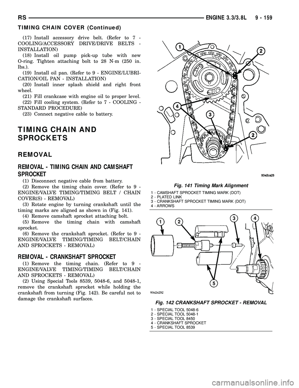
(3) Rotate engine by turning crankshaft until the
timing marks are aligned as shown in (Fig. 141).
(4) Remove camshaft sprocket attaching bolt.
(5) Remove the timing chain with camshaft
sprocket.
(6) Remove the crankshaft sprocket. (Refer to 9 -
ENGINE/VALVE TIMING/TIMING BELT/CHAIN
AND SPROCKETS - REMOVAL)
REMOVAL - CRANKSHAFT SPROCKET
(1) Remove the timing chain. (Refer to 9 -
ENGINE/VALVE TIMING/TIMING BELT/CHAIN
AND SPROCKETS - REMOVAL)
(2) Using Special Tools 8539, 5048-6, and 5048-1,
remove the crankshaft sprocket while holding the
crankshaft from turning (Fig. 142). Be careful not to
damage the crankshaft surfaces.
Fig. 141 Timing Mark Alignment
1 - CAMSHAFT SPROCKET TIMING MARK (DOT)
2 - PLATED LINK
3 - CRANKSHAFT SPROCKET TIMING MARK (DOT)
4 - ARROWS
Fig. 142 CRANKSHAFT SPROCKET - REMOVAL
1 - SPECIAL TOOL 5048-6
2 - SPECIAL TOOL 5048-1
3 - SPECIAL TOOL 8450
4 - CRANKSHAFT SPROCKET
5 - SPECIAL TOOL 8539
RSENGINE 3.3/3.8L9 - 159
TIMING CHAIN COVER (Continued)
Page 1337 of 2339
INSTALLATION
INSTALLATION - CRANKSHAFT SPROCKET
(1) Position the sprocket on the crankshaft (timing
mark out) with the timing slot aligned with the tim-
ing pin.
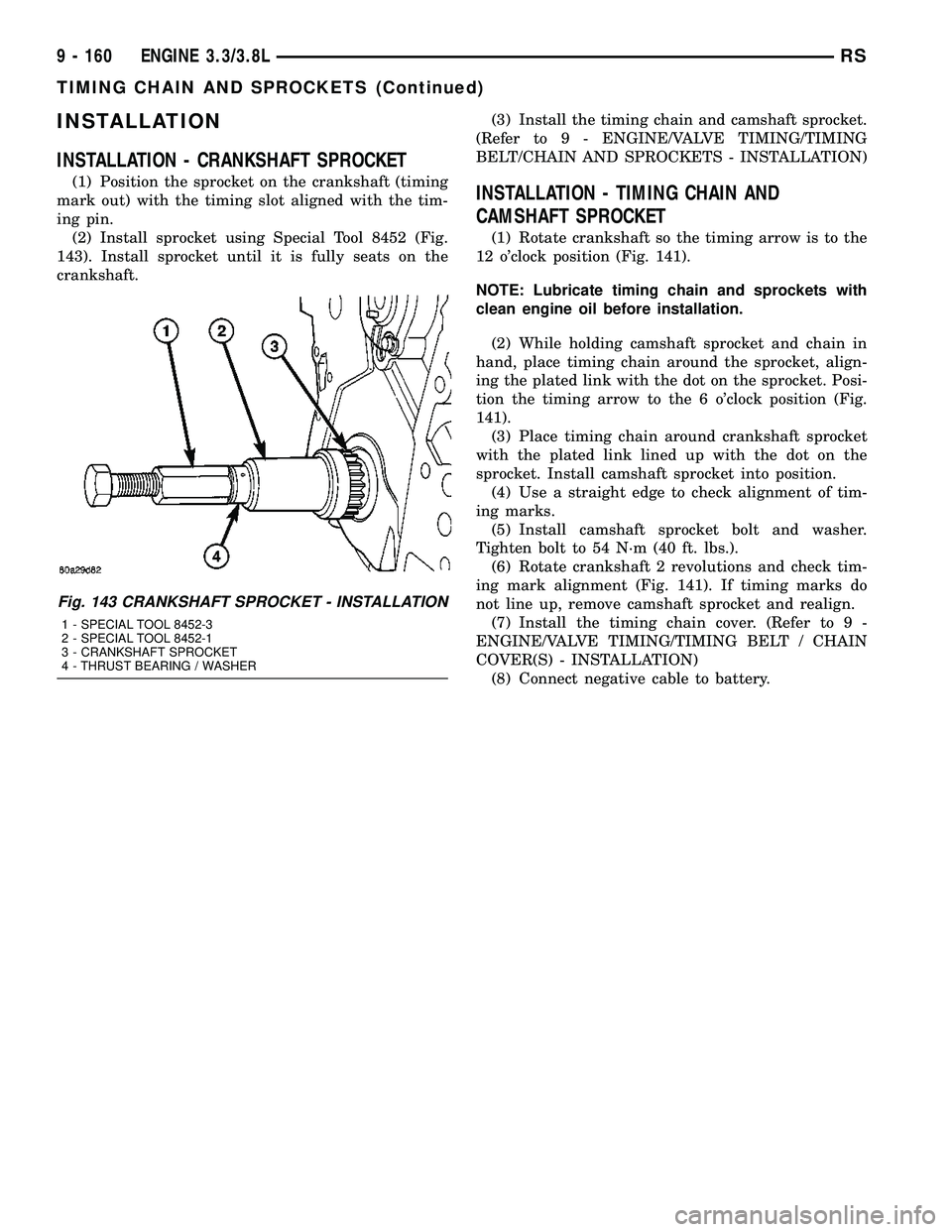
(2) Install sprocket using Special Tool 8452 (Fig.
143). Install sprocket until it is fully seats on the
crankshaft.(3) Install the timing chain and camshaft sprocket.
(Refer to 9 - ENGINE/VALVE TIMING/TIMING
BELT/CHAIN AND SPROCKETS - INSTALLATION)INSTALLATION - TIMING CHAIN AND
CAMSHAFT SPROCKET
(1) Rotate crankshaft so the timing arrow is to the
12 o'clock position (Fig. 141).
NOTE: Lubricate timing chain and sprockets with
clean engine oil before installation.
(2) While holding camshaft sprocket and chain in
hand, place timing chain around the sprocket, align-
ing the plated link with the dot on the sprocket. Posi-
tion the timing arrow to the 6 o'clock position (Fig.
141).
(3) Place timing chain around crankshaft sprocket
with the plated link lined up with the dot on the
sprocket. Install camshaft sprocket into position.
(4) Use a straight edge to check alignment of tim-
ing marks.
(5) Install camshaft sprocket bolt and washer.
Tighten bolt to 54 N´m (40 ft. lbs.).
(6) Rotate crankshaft 2 revolutions and check tim-
ing mark alignment (Fig. 141). If timing marks do
not line up, remove camshaft sprocket and realign.
(7) Install the timing chain cover. (Refer to 9 -
ENGINE/VALVE TIMING/TIMING BELT / CHAIN
COVER(S) - INSTALLATION)
(8) Connect negative cable to battery.
Fig. 143 CRANKSHAFT SPROCKET - INSTALLATION
1 - SPECIAL TOOL 8452-3
2 - SPECIAL TOOL 8452-1
3 - CRANKSHAFT SPROCKET
4 - THRUST BEARING / WASHER
9 - 160 ENGINE 3.3/3.8LRS
TIMING CHAIN AND SPROCKETS (Continued)
Page 1344 of 2339
HEAT SHIELDS
DESCRIPTION
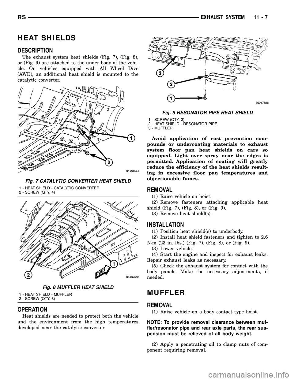
The exhaust system heat shields (Fig. 7), (Fig. 8),
or (Fig. 9) are attached to the under body of the vehi-
cle. On vehicles equipped with All Wheel Dive
(AWD), an additional heat shield is mounted to the
catalytic converter.
OPERATION
Heat shields are needed to protect both the vehicle
and the environment from the high temperatures
developed near the catalytic converter.Avoid application of rust prevention com-
pounds or undercoating materials to exhaust
system floor pan heat shields on cars so
equipped. Light over spray near the edges is
permitted. Application of coating will greatly
reduce the efficiency of the heat shields result-
ing in excessive floor pan temperatures and
objectionable fumes.
REMOVAL
(1) Raise vehicle on hoist.
(2) Remove fasteners attaching applicable heat
shield (Fig. 7), (Fig. 8), or (Fig. 9).
(3) Remove heat shield(s).
INSTALLATION
(1) Position heat shield(s) to underbody.
(2) Install heat shield fasteners and tighten to 2.6
N´m (23 in. lbs.) (Fig. 7), (Fig. 8), or (Fig. 9).
(3) Lower vehicle.
(4) Start the engine and inspect for exhaust leaks.
Repair exhaust leaks as necessary.
(5) Check the exhaust system for contact with the
body panels. Make the necessary adjustments, if
needed.
MUFFLER
REMOVAL
(1) Raise vehicle on a body contact type hoist.
NOTE: To provide removal clearance between muf-
fler/resonator pipe and rear axle parts, the rear sus-
pension must be relieved of all body weight.
(2) Apply a penetrating oil to clamp nuts of com-
ponent requiring removal.
Fig. 7 CATALYTIC CONVERTER HEAT SHIELD
1 - HEAT SHIELD - CATALYTIC CONVERTER
2 - SCREW (QTY. 4)
Fig. 8 MUFFLER HEAT SHIELD
1 - HEAT SHIELD - MUFFLER
2 - SCREW (QTY. 6)
Fig. 9 RESONATOR PIPE HEAT SHIELD
1 - SCREW (QTY. 3)
2 - HEAT SHIELD - RESONATOR PIPE
3 - MUFFLER
RSEXHAUST SYSTEM11-7
Page 1361 of 2339
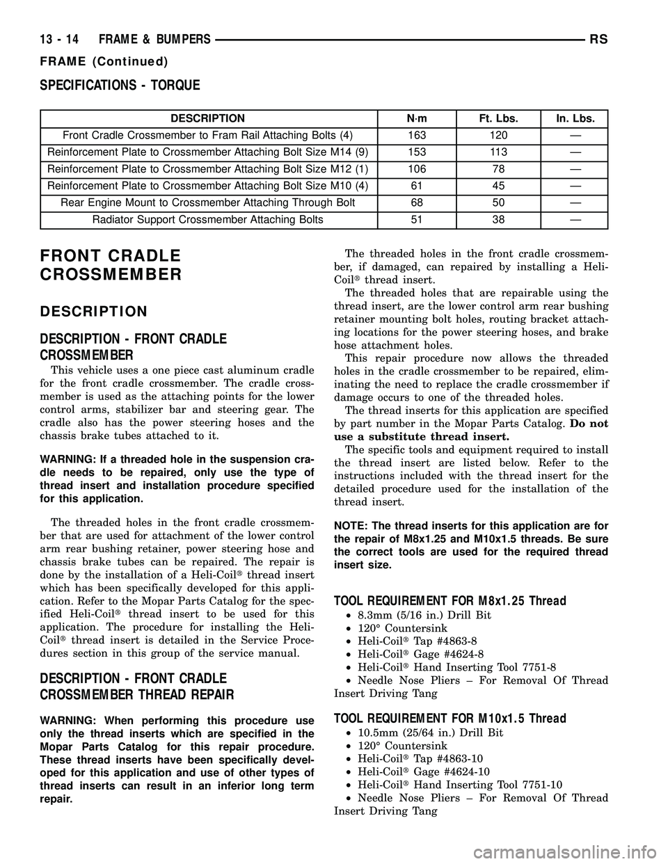
SPECIFICATIONS - TORQUE
DESCRIPTION N´m Ft. Lbs. In. Lbs.
Front Cradle Crossmember to Fram Rail Attaching Bolts (4) 163 120 Ð
Reinforcement Plate to Crossmember Attaching Bolt Size M14 (9) 153 113 Ð
Reinforcement Plate to Crossmember Attaching Bolt Size M12 (1) 106 78 Ð
Reinforcement Plate to Crossmember Attaching Bolt Size M10 (4) 61 45 Ð
Rear Engine Mount to Crossmember Attaching Through Bolt 68 50 Ð
Radiator Support Crossmember Attaching Bolts 51 38 Ð
FRONT CRADLE
CROSSMEMBER
DESCRIPTION
DESCRIPTION - FRONT CRADLE
CROSSMEMBER
This vehicle uses a one piece cast aluminum cradle
for the front cradle crossmember. The cradle cross-
member is used as the attaching points for the lower
control arms, stabilizer bar and steering gear. The
cradle also has the power steering hoses and the
chassis brake tubes attached to it.
WARNING: If a threaded hole in the suspension cra-
dle needs to be repaired, only use the type of
thread insert and installation procedure specified
for this application.
The threaded holes in the front cradle crossmem-
ber that are used for attachment of the lower control
arm rear bushing retainer, power steering hose and
chassis brake tubes can be repaired. The repair is
done by the installation of a Heli-Coiltthread insert
which has been specifically developed for this appli-
cation. Refer to the Mopar Parts Catalog for the spec-
ified Heli-Coiltthread insert to be used for this
application. The procedure for installing the Heli-
Coiltthread insert is detailed in the Service Proce-
dures section in this group of the service manual.
DESCRIPTION - FRONT CRADLE
CROSSMEMBER THREAD REPAIR
WARNING: When performing this procedure use
only the thread inserts which are specified in the
Mopar Parts Catalog for this repair procedure.
These thread inserts have been specifically devel-
oped for this application and use of other types of
thread inserts can result in an inferior long term
repair.The threaded holes in the front cradle crossmem-
ber, if damaged, can repaired by installing a Heli-
Coiltthread insert.
The threaded holes that are repairable using the
thread insert, are the lower control arm rear bushing
retainer mounting bolt holes, routing bracket attach-
ing locations for the power steering hoses, and brake
hose attachment holes.
This repair procedure now allows the threaded
holes in the cradle crossmember to be repaired, elim-
inating the need to replace the cradle crossmember if
damage occurs to one of the threaded holes.
The thread inserts for this application are specified
by part number in the Mopar Parts Catalog.Do not
use a substitute thread insert.
The specific tools and equipment required to install
the thread insert are listed below. Refer to the
instructions included with the thread insert for the
detailed procedure used for the installation of the
thread insert.
NOTE: The thread inserts for this application are for
the repair of M8x1.25 and M10x1.5 threads. Be sure
the correct tools are used for the required thread
insert size.
TOOL REQUIREMENT FOR M8x1.25 Thread
²8.3mm (5/16 in.) Drill Bit
²120É Countersink
²Heli-CoiltTap #4863-8
²Heli-CoiltGage #4624-8
²Heli-CoiltHand Inserting Tool 7751-8
²Needle Nose Pliers ± For Removal Of Thread
Insert Driving Tang
TOOL REQUIREMENT FOR M10x1.5 Thread
²10.5mm (25/64 in.) Drill Bit
²120É Countersink
²Heli-CoiltTap #4863-10
²Heli-CoiltGage #4624-10
²Heli-CoiltHand Inserting Tool 7751-10
²Needle Nose Pliers ± For Removal Of Thread
Insert Driving Tang
13 - 14 FRAME & BUMPERSRS
FRAME (Continued)
Page 1362 of 2339
REMOVAL
The front cradle crossmember must be installed in
the design location to achieve proper front end sus-
pension alignment. If the cradle crossmember is
removed without applying reference marks on the
frame rails, align the cradle crossmember according
to the dimensions provided in this group.
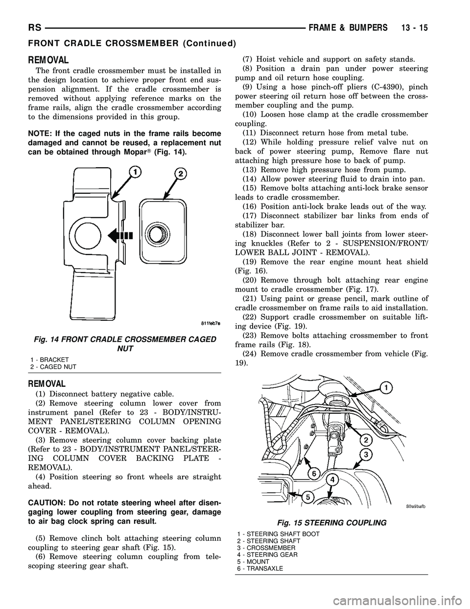
NOTE: If the caged nuts in the frame rails become
damaged and cannot be reused, a replacement nut
can be obtained through MoparT(Fig. 14).
REMOVAL
(1) Disconnect battery negative cable.
(2) Remove steering column lower cover from
instrument panel (Refer to 23 - BODY/INSTRU-
MENT PANEL/STEERING COLUMN OPENING
COVER - REMOVAL).
(3) Remove steering column cover backing plate
(Refer to 23 - BODY/INSTRUMENT PANEL/STEER-
ING COLUMN COVER BACKING PLATE -
REMOVAL).
(4) Position steering so front wheels are straight
ahead.
CAUTION: Do not rotate steering wheel after disen-
gaging lower coupling from steering gear, damage
to air bag clock spring can result.
(5) Remove clinch bolt attaching steering column
coupling to steering gear shaft (Fig. 15).
(6) Remove steering column coupling from tele-
scoping steering gear shaft.(7) Hoist vehicle and support on safety stands.
(8) Position a drain pan under power steering
pump and oil return hose coupling.
(9) Using a hose pinch-off pliers (C-4390), pinch
power steering oil return hose off between the cross-
member coupling and the pump.
(10) Loosen hose clamp at the cradle crossmember
coupling.
(11) Disconnect return hose from metal tube.
(12) While holding pressure relief valve nut on
back of power steering pump, Remove flare nut
attaching high pressure hose to back of pump.
(13) Remove high pressure hose from pump.
(14) Allow power steering fluid to drain into pan.
(15) Remove bolts attaching anti-lock brake sensor
leads to cradle crossmember.
(16) Position anti-lock brake leads out of the way.
(17) Disconnect stabilizer bar links from ends of
stabilizer bar.
(18) Disconnect lower ball joints from lower steer-
ing knuckles (Refer to 2 - SUSPENSION/FRONT/
LOWER BALL JOINT - REMOVAL).
(19) Remove the rear engine mount heat shield
(Fig. 16).
(20) Remove through bolt attaching rear engine
mount to cradle crossmember (Fig. 17).
(21) Using paint or grease pencil, mark outline of
cradle crossmember on frame rails to aid installation.
(22) Support cradle crossmember on suitable lift-
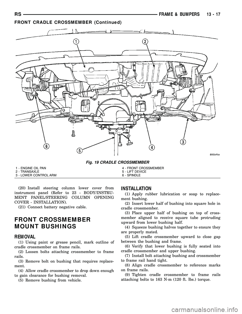
ing device (Fig. 19).
(23) Remove bolts attaching crossmember to front
frame rails (Fig. 18).
(24) Remove cradle crossmember from vehicle (Fig.
19).
Fig. 14 FRONT CRADLE CROSSMEMBER CAGED
NUT
1 - BRACKET
2 - CAGED NUT
Fig. 15 STEERING COUPLING
1 - STEERING SHAFT BOOT
2 - STEERING SHAFT
3 - CROSSMEMBER
4 - STEERING GEAR
5 - MOUNT
6 - TRANSAXLE
RSFRAME & BUMPERS13-15
FRONT CRADLE CROSSMEMBER (Continued)
Page 1364 of 2339
(20) Install steering column lower cover from
instrument panel (Refer to 23 - BODY/INSTRU-
MENT PANEL/STEERING COLUMN OPENING
COVER - INSTALLATION).
(21) Connect battery negative cable.
FRONT CROSSMEMBER
MOUNT BUSHINGS
REMOVAL
(1) Using paint or grease pencil, mark outline of
cradle crossmember on frame rails.
(2) Loosen bolts attaching crossmember to frame
rails.
(3) Remove bolt on bushing that requires replace-
ment.
(4) Allow cradle crossmember to drop down enough
to gain clearance for bushing removal.
(5) Remove bushing from vehicle.
INSTALLATION
(1) Apply rubber lubrication or soap to replace-
ment bushing.
(2) Insert lower half of bushing into square hole in
cradle crossmember.
(3) Place upper half of bushing on top of cross-
member aligned to receive square tube protruding
upward from lower bushing half.
(4) Squeeze bushing halves together to ensure they
are properly mated.
(5) Lift cradle crossmember upward to close gap
between the bushing and frame.
(6) Verify that lower bushing is fully seated into
cradle crossmember and upper bushing.
(7) Install bolt attaching bushing and crossmember
to frame rail hand tight.
(8) Align cradle crossmember to reference marks
on frame rails.
(9) Tighten cradle crossmember to frame rails
attaching bolts to 163 N´m (120 ft. lbs.) torque.
Fig. 19 CRADLE CROSSMEMBER
1 - ENGINE OIL PAN
2 - TRANSAXLE
3 - LOWER CONTROL ARM4 - FRONT CROSSMEMBER
5 - LIFT DEVICE
6 - SPINDLE
RSFRAME & BUMPERS13-17
FRONT CRADLE CROSSMEMBER (Continued)
Page 1373 of 2339
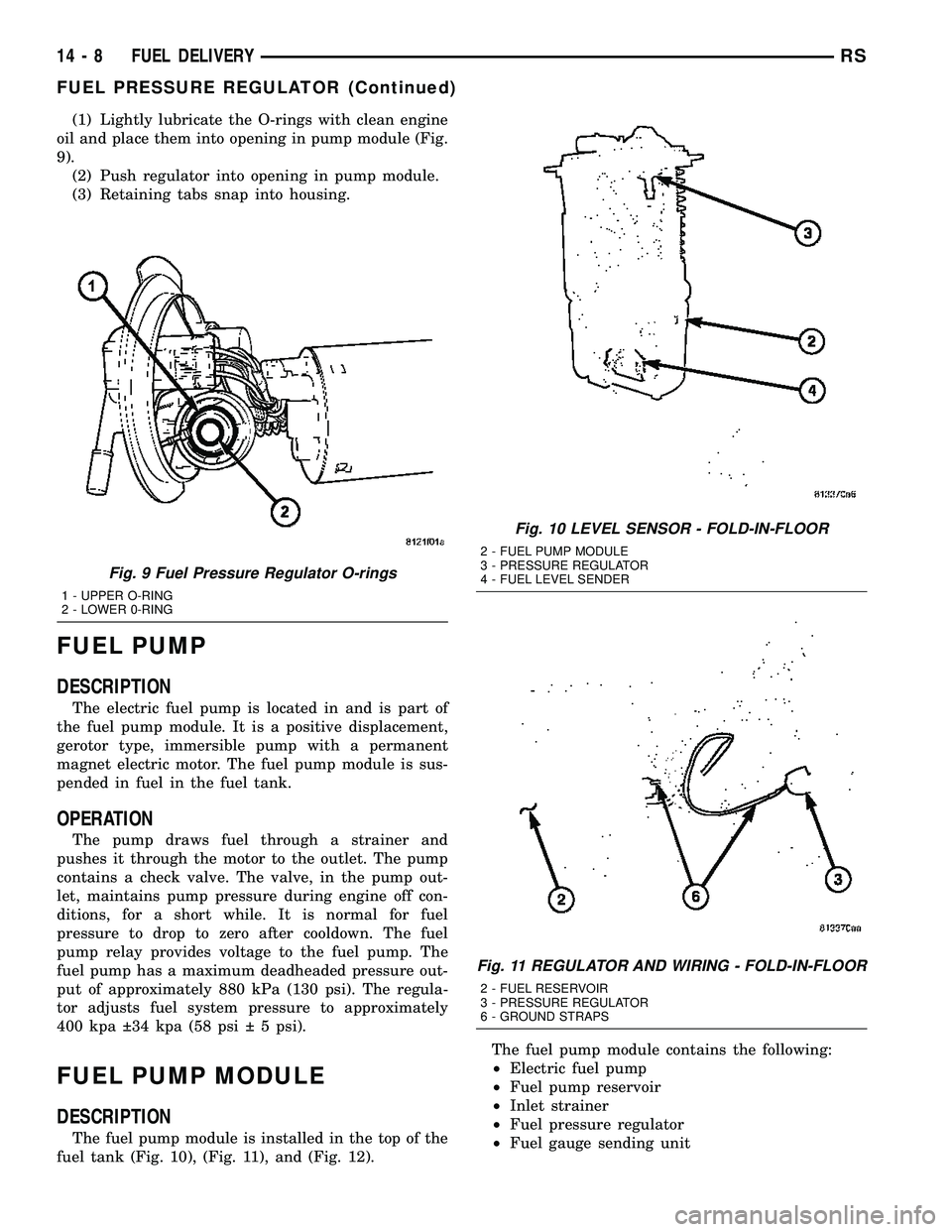
(1) Lightly lubricate the O-rings with clean engine
oil and place them into opening in pump module (Fig.
9).
(2) Push regulator into opening in pump module.
(3) Retaining tabs snap into housing.
FUEL PUMP
DESCRIPTION
The electric fuel pump is located in and is part of
the fuel pump module. It is a positive displacement,
gerotor type, immersible pump with a permanent
magnet electric motor. The fuel pump module is sus-
pended in fuel in the fuel tank.
OPERATION
The pump draws fuel through a strainer and
pushes it through the motor to the outlet. The pump
contains a check valve. The valve, in the pump out-
let, maintains pump pressure during engine off con-
ditions, for a short while. It is normal for fuel
pressure to drop to zero after cooldown. The fuel
pump relay provides voltage to the fuel pump. The
fuel pump has a maximum deadheaded pressure out-
put of approximately 880 kPa (130 psi). The regula-
tor adjusts fuel system pressure to approximately
400 kpa 34 kpa (58 psi 5 psi).
FUEL PUMP MODULE
DESCRIPTION
The fuel pump module is installed in the top of the
fuel tank (Fig. 10), (Fig. 11), and (Fig. 12).The fuel pump module contains the following:
²Electric fuel pump
²Fuel pump reservoir
²Inlet strainer
²Fuel pressure regulator
²Fuel gauge sending unit
Fig. 9 Fuel Pressure Regulator O-rings
1 - UPPER O-RING
2 - LOWER 0-RING
Fig. 10 LEVEL SENSOR - FOLD-IN-FLOOR
2 - FUEL PUMP MODULE
3 - PRESSURE REGULATOR
4 - FUEL LEVEL SENDER
Fig. 11 REGULATOR AND WIRING - FOLD-IN-FLOOR
2 - FUEL RESERVOIR
3 - PRESSURE REGULATOR
6 - GROUND STRAPS
14 - 8 FUEL DELIVERYRS
FUEL PRESSURE REGULATOR (Continued)