2005 CHRYSLER CARAVAN steering
[x] Cancel search: steeringPage 1422 of 2339
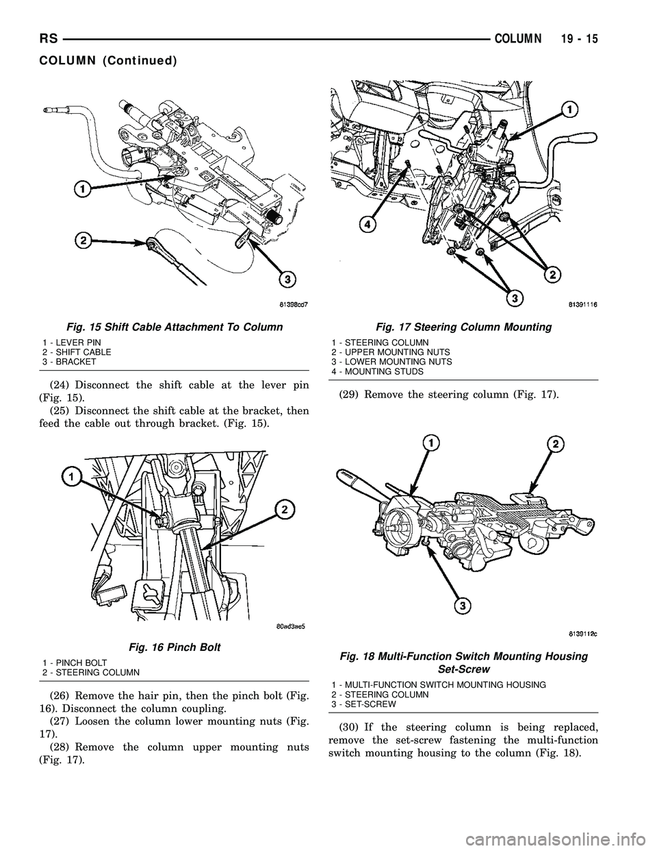
(24) Disconnect the shift cable at the lever pin
(Fig. 15).
(25) Disconnect the shift cable at the bracket, then
feed the cable out through bracket. (Fig. 15).
(26) Remove the hair pin, then the pinch bolt (Fig.
16). Disconnect the column coupling.
(27) Loosen the column lower mounting nuts (Fig.
17).
(28) Remove the column upper mounting nuts
(Fig. 17).(29) Remove the steering column (Fig. 17).
(30) If the steering column is being replaced,
remove the set-screw fastening the multi-function
switch mounting housing to the column (Fig. 18).
Fig. 15 Shift Cable Attachment To Column
1 - LEVER PIN
2 - SHIFT CABLE
3 - BRACKET
Fig. 16 Pinch Bolt
1 - PINCH BOLT
2 - STEERING COLUMN
Fig. 17 Steering Column Mounting
1 - STEERING COLUMN
2 - UPPER MOUNTING NUTS
3 - LOWER MOUNTING NUTS
4 - MOUNTING STUDS
Fig. 18 Multi-Function Switch Mounting Housing
Set-Screw
1 - MULTI-FUNCTION SWITCH MOUNTING HOUSING
2 - STEERING COLUMN
3 - SET-SCREW
RSCOLUMN19-15
COLUMN (Continued)
Page 1423 of 2339
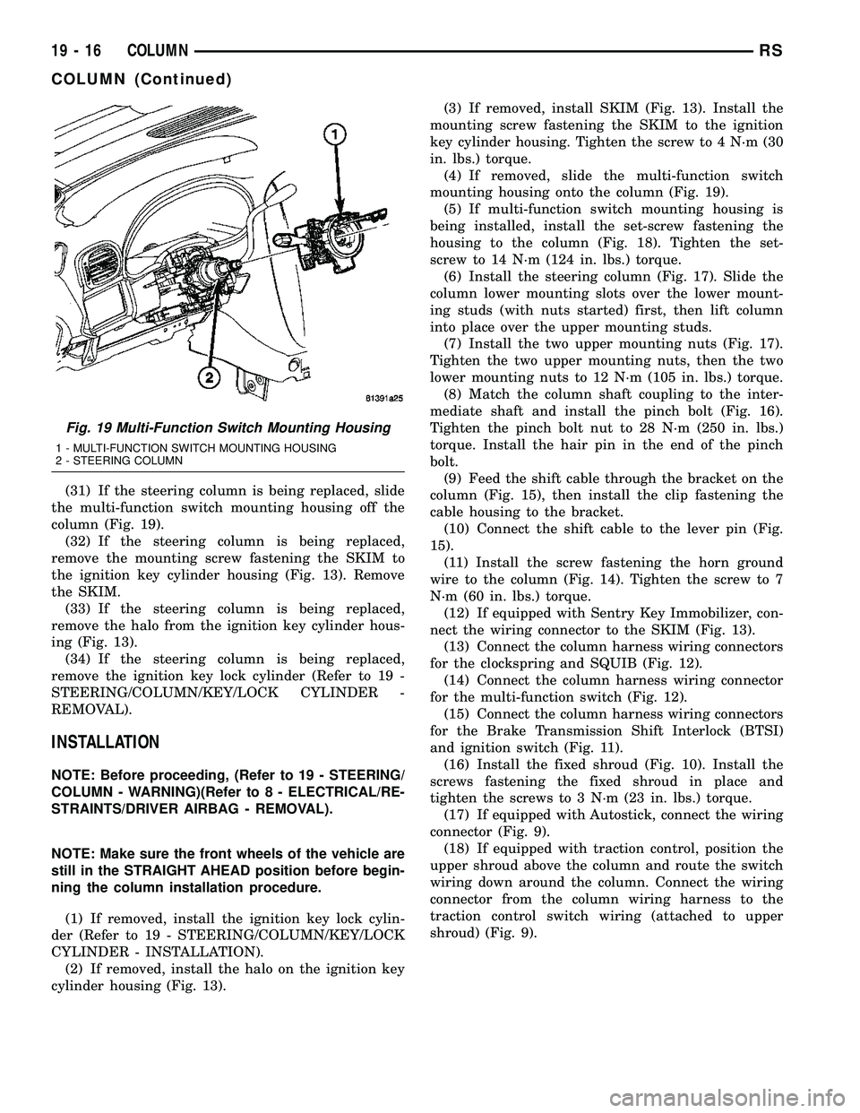
(31) If the steering column is being replaced, slide
the multi-function switch mounting housing off the
column (Fig. 19).
(32) If the steering column is being replaced,
remove the mounting screw fastening the SKIM to
the ignition key cylinder housing (Fig. 13). Remove
the SKIM.
(33) If the steering column is being replaced,
remove the halo from the ignition key cylinder hous-
ing (Fig. 13).
(34) If the steering column is being replaced,
remove the ignition key lock cylinder (Refer to 19 -
STEERING/COLUMN/KEY/LOCK CYLINDER -
REMOVAL).
INSTALLATION
NOTE: Before proceeding, (Refer to 19 - STEERING/
COLUMN - WARNING)(Refer to 8 - ELECTRICAL/RE-
STRAINTS/DRIVER AIRBAG - REMOVAL).
NOTE: Make sure the front wheels of the vehicle are
still in the STRAIGHT AHEAD position before begin-
ning the column installation procedure.
(1) If removed, install the ignition key lock cylin-
der (Refer to 19 - STEERING/COLUMN/KEY/LOCK
CYLINDER - INSTALLATION).
(2) If removed, install the halo on the ignition key
cylinder housing (Fig. 13).(3) If removed, install SKIM (Fig. 13). Install the
mounting screw fastening the SKIM to the ignition
key cylinder housing. Tighten the screw to 4 N´m (30
in. lbs.) torque.
(4) If removed, slide the multi-function switch
mounting housing onto the column (Fig. 19).
(5) If multi-function switch mounting housing is
being installed, install the set-screw fastening the
housing to the column (Fig. 18). Tighten the set-
screw to 14 N´m (124 in. lbs.) torque.
(6) Install the steering column (Fig. 17). Slide the
column lower mounting slots over the lower mount-
ing studs (with nuts started) first, then lift column
into place over the upper mounting studs.
(7) Install the two upper mounting nuts (Fig. 17).
Tighten the two upper mounting nuts, then the two
lower mounting nuts to 12 N´m (105 in. lbs.) torque.
(8) Match the column shaft coupling to the inter-
mediate shaft and install the pinch bolt (Fig. 16).
Tighten the pinch bolt nut to 28 N´m (250 in. lbs.)
torque. Install the hair pin in the end of the pinch
bolt.
(9) Feed the shift cable through the bracket on the
column (Fig. 15), then install the clip fastening the
cable housing to the bracket.
(10) Connect the shift cable to the lever pin (Fig.
15).
(11) Install the screw fastening the horn ground
wire to the column (Fig. 14). Tighten the screw to 7
N´m (60 in. lbs.) torque.
(12) If equipped with Sentry Key Immobilizer, con-
nect the wiring connector to the SKIM (Fig. 13).
(13) Connect the column harness wiring connectors
for the clockspring and SQUIB (Fig. 12).
(14) Connect the column harness wiring connector
for the multi-function switch (Fig. 12).
(15) Connect the column harness wiring connectors
for the Brake Transmission Shift Interlock (BTSI)
and ignition switch (Fig. 11).
(16) Install the fixed shroud (Fig. 10). Install the
screws fastening the fixed shroud in place and
tighten the screws to 3 N´m (23 in. lbs.) torque.
(17) If equipped with Autostick, connect the wiring
connector (Fig. 9).
(18) If equipped with traction control, position the
upper shroud above the column and route the switch
wiring down around the column. Connect the wiring
connector from the column wiring harness to the
traction control switch wiring (attached to upper
shroud) (Fig. 9).
Fig. 19 Multi-Function Switch Mounting Housing
1 - MULTI-FUNCTION SWITCH MOUNTING HOUSING
2 - STEERING COLUMN
19 - 16 COLUMNRS
COLUMN (Continued)
Page 1424 of 2339

(19) Position the lower shroud on the column (Fig.
8). Install the lower shroud mounting screw. Tighten
the screw to 2 N´m (17 in. lbs.) torque.
(20) If equipped with adjustable pedals, Connect
the wiring connector for the switch (Fig. 7) to the col-
umn wiring harness.
(21) Position the upper shroud on top of the lower
shroud and snap it into place. Install the upper
shroud mounting screws (Fig. 6). Tighten the screws
to 2 N´m (17 in. lbs.) torque.
(22) Inspect shroud mating surfaces for excessive
gaps and correct as necessary.
(23) Install the cluster trim bezel (Refer to 23 -
BODY/INSTRUMENT PANEL/CLUSTER BEZEL -
INSTALLATION).
(24) Install the knee blocker/steering column cover
plate. (Refer to 23 - BODY/INSTRUMENT PANEL/
KNEE BLOCKER - INSTALLATION)
(25) Install the parking brake handle link.
(26) Install the knee blocker/steering column open-
ing cover. (Refer to 23 - BODY/INSTRUMENT PAN-
EL/STEERING COLUMN OPENING COVER -
INSTALLATION)
(27) Align the splines and install the steering
wheel on the steering column shaft(Refer to 19 -
STEERING/COLUMN/STEERING WHEEL -
INSTALLATION).
(28) Install the damper over the steering column
shaft (Fig. 4).
(29) Install the steering wheel retaining bolt (Fig.
4). Tighten the bolt to 61 N´m (45 ft. lbs.) torque.
(30) If the steering wheel is equipped with remote
audio controls, connect the wiring connector to the
clockspring (Fig. 4).
(31) Connect the two squib connectors to the
driver airbag (Fig. 3). The connectors are color coded
to avoid connector mix-up.
(32) Connect the speed control and horn connector
to the clockspring (Fig. 3).
(33) Install the airbag to the steering wheel.
Install the driver airbag mounting screws (Fig. 2).
Tighten screws to 10 N´m (90 in. lbs.) torque.
(34) Connect the battery negative (ground) cable to
battery post following special Diagnosis And Testing
procedure. (Refer to 8 - ELECTRICAL/RESTRAINTS
- DIAGNOSIS AND TESTING)
(35) Check operation of all steering column
mounted components.
(36) Road test vehicle to ensure proper operation
of steering.SPECIFICATIONS
COLUMN FASTENER TORQUE
DESCRIPTION N´mFt.
Lbs.In.
Lbs.
Driver Airbag Mounting Screws 10 Ð 90
Multi-Function Switch Mounting
Housing Set-Screw14 Ð 124
Shroud Attaching Screws - Fixed 3 Ð 23
Shroud Attaching Screws -
Lower/Upper2Ð17
SKIM Attaching Screw 4 Ð 30
Steering Column Coupling Pinch
Bolt28 Ð 250
Steering Column Mounting Nuts 12 Ð 105
Steering Wheel Retaining Bolt 61 45 Ð
IGNITION SWITCH
REMOVAL
The ignition switch attaches to the lock cylinder
housing on the end opposite the lock cylinder (Fig.
20). For ignition switch terminal and circuit identifi-
cation, refer to the appropriate wiring information.
The wiring information includes wiring diagrams,
proper wire and connector repair procedures, further
details on wire harness routing and retention, as well
as pin-out and location views for the various wire
harness connectors, splices and grounds.
(1) Disconnect negative cable from battery.
Fig. 20 Ignition SwitchÐViewed From Below
Column
1 - IGNITION SWITCH
2 - LOCK CYLINDER HOUSING
3 - RETAINING TABS
RSCOLUMN19-17
COLUMN (Continued)
Page 1425 of 2339
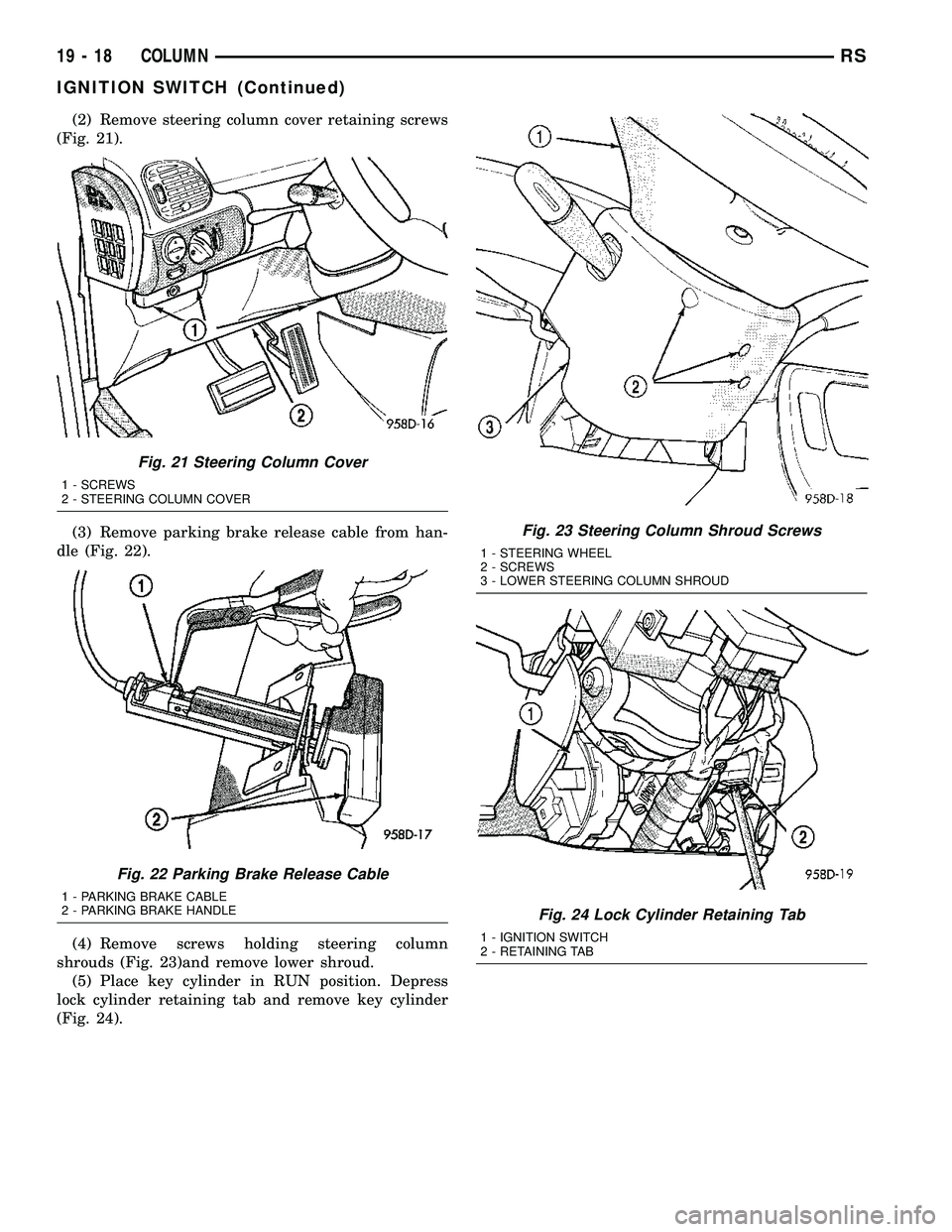
(2) Remove steering column cover retaining screws
(Fig. 21).
(3) Remove parking brake release cable from han-
dle (Fig. 22).
(4) Remove screws holding steering column
shrouds (Fig. 23)and remove lower shroud.
(5) Place key cylinder in RUN position. Depress
lock cylinder retaining tab and remove key cylinder
(Fig. 24).
Fig. 21 Steering Column Cover
1 - SCREWS
2 - STEERING COLUMN COVER
Fig. 22 Parking Brake Release Cable
1 - PARKING BRAKE CABLE
2 - PARKING BRAKE HANDLE
Fig. 23 Steering Column Shroud Screws
1 - STEERING WHEEL
2 - SCREWS
3 - LOWER STEERING COLUMN SHROUD
Fig. 24 Lock Cylinder Retaining Tab
1 - IGNITION SWITCH
2 - RETAINING TAB
19 - 18 COLUMNRS
IGNITION SWITCH (Continued)
Page 1426 of 2339
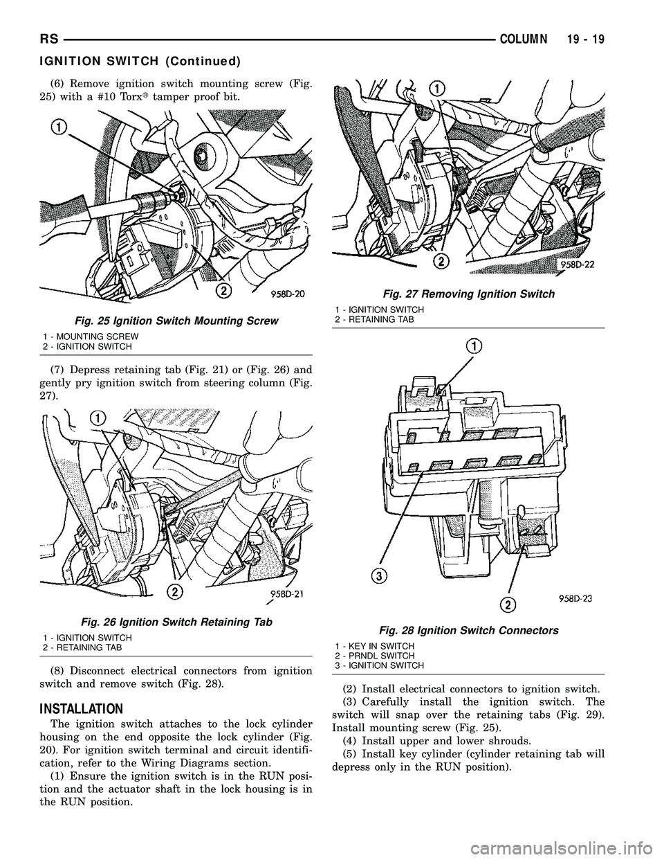
(6) Remove ignition switch mounting screw (Fig.
25) with a #10 Torxttamper proof bit.
(7) Depress retaining tab (Fig. 21) or (Fig. 26) and
gently pry ignition switch from steering column (Fig.
27).
(8) Disconnect electrical connectors from ignition
switch and remove switch (Fig. 28).
INSTALLATION
The ignition switch attaches to the lock cylinder
housing on the end opposite the lock cylinder (Fig.
20). For ignition switch terminal and circuit identifi-
cation, refer to the Wiring Diagrams section.
(1) Ensure the ignition switch is in the RUN posi-
tion and the actuator shaft in the lock housing is in
the RUN position.(2) Install electrical connectors to ignition switch.
(3) Carefully install the ignition switch. The
switch will snap over the retaining tabs (Fig. 29).
Install mounting screw (Fig. 25).
(4) Install upper and lower shrouds.
(5) Install key cylinder (cylinder retaining tab will
depress only in the RUN position).
Fig. 25 Ignition Switch Mounting Screw
1 - MOUNTING SCREW
2 - IGNITION SWITCH
Fig. 26 Ignition Switch Retaining Tab
1 - IGNITION SWITCH
2 - RETAINING TAB
Fig. 27 Removing Ignition Switch
1 - IGNITION SWITCH
2 - RETAINING TAB
Fig. 28 Ignition Switch Connectors
1 - KEY IN SWITCH
2 - PRNDL SWITCH
3 - IGNITION SWITCH
RSCOLUMN19-19
IGNITION SWITCH (Continued)
Page 1427 of 2339
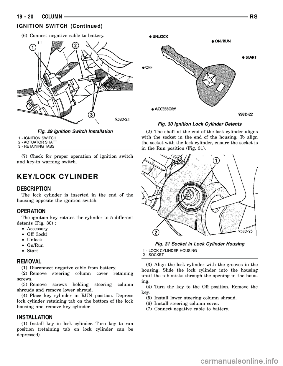
(6) Connect negative cable to battery.
(7) Check for proper operation of ignition switch
and key-in warning switch.
KEY/LOCK CYLINDER
DESCRIPTION
The lock cylinder is inserted in the end of the
housing opposite the ignition switch.
OPERATION
The ignition key rotates the cylinder to 5 different
detents (Fig. 30) :
²Accessory
²Off (lock)
²Unlock
²On/Run
²Start
REMOVAL
(1) Disconnect negative cable from battery.
(2) Remove steering column cover retaining
screws.
(3) Remove screws holding steering column
shrouds and remove lower shroud.
(4) Place key cylinder in RUN position. Depress
lock cylinder retaining tab on the bottom of the lock
housing and remove key cylinder.
INSTALLATION
(1) Install key in lock cylinder. Turn key to run
position (retaining tab on lock cylinder can be
depressed).(2) The shaft at the end of the lock cylinder aligns
with the socket in the end of the housing. To align
the socket with the lock cylinder, ensure the socket is
in the Run position (Fig. 31).
(3) Align the lock cylinder with the grooves in the
housing. Slide the lock cylinder into the housing
until the tab sticks through the opening in the hous-
ing.
(4) Turn the key to the Off position. Remove the
key.
(5) Install lower steering column shroud.
(6) Install steering column cover.
(7) Connect negative cable to battery.
Fig. 29 Ignition Switch Installation
1 - IGNITION SWITCH
2 - ACTUATOR SHAFT
3 - RETAINING TABS
Fig. 30 Ignition Lock Cylinder Detents
Fig. 31 Socket in Lock Cylinder Housing
1 - LOCK CYLINDER HOUSING
2 - SOCKET
19 - 20 COLUMNRS
IGNITION SWITCH (Continued)
Page 1428 of 2339
SHROUD - LOWER
REMOVAL
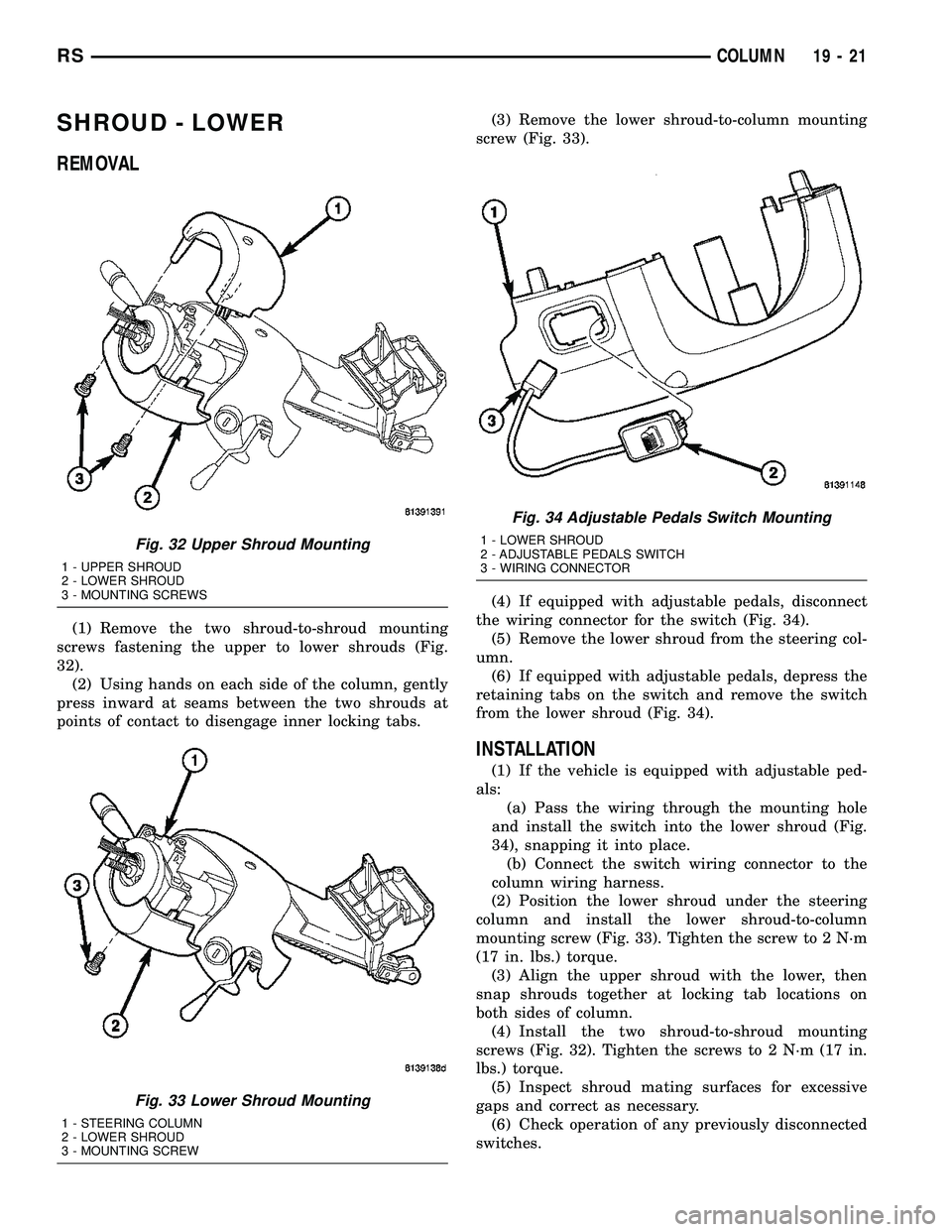
(1) Remove the two shroud-to-shroud mounting
screws fastening the upper to lower shrouds (Fig.
32).
(2) Using hands on each side of the column, gently
press inward at seams between the two shrouds at
points of contact to disengage inner locking tabs.(3) Remove the lower shroud-to-column mounting
screw (Fig. 33).
(4) If equipped with adjustable pedals, disconnect
the wiring connector for the switch (Fig. 34).
(5) Remove the lower shroud from the steering col-
umn.
(6) If equipped with adjustable pedals, depress the
retaining tabs on the switch and remove the switch
from the lower shroud (Fig. 34).
INSTALLATION
(1) If the vehicle is equipped with adjustable ped-
als:
(a) Pass the wiring through the mounting hole
and install the switch into the lower shroud (Fig.
34), snapping it into place.
(b) Connect the switch wiring connector to the
column wiring harness.
(2) Position the lower shroud under the steering
column and install the lower shroud-to-column
mounting screw (Fig. 33). Tighten the screw to 2 N´m
(17 in. lbs.) torque.
(3) Align the upper shroud with the lower, then
snap shrouds together at locking tab locations on
both sides of column.
(4) Install the two shroud-to-shroud mounting
screws (Fig. 32). Tighten the screws to 2 N´m (17 in.
lbs.) torque.
(5) Inspect shroud mating surfaces for excessive
gaps and correct as necessary.
(6) Check operation of any previously disconnected
switches.
Fig. 32 Upper Shroud Mounting
1 - UPPER SHROUD
2 - LOWER SHROUD
3 - MOUNTING SCREWS
Fig. 33 Lower Shroud Mounting
1 - STEERING COLUMN
2 - LOWER SHROUD
3 - MOUNTING SCREW
Fig. 34 Adjustable Pedals Switch Mounting
1 - LOWER SHROUD
2 - ADJUSTABLE PEDALS SWITCH
3 - WIRING CONNECTOR
RSCOLUMN19-21
Page 1429 of 2339
SHROUD - UPPER
REMOVAL
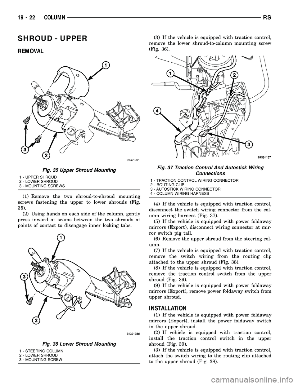
(1) Remove the two shroud-to-shroud mounting
screws fastening the upper to lower shrouds (Fig.
35).
(2) Using hands on each side of the column, gently
press inward at seams between the two shrouds at
points of contact to disengage inner locking tabs.(3) If the vehicle is equipped with traction control,
remove the lower shroud-to-column mounting screw
(Fig. 36).
(4) If the vehicle is equipped with traction control,
disconnect the switch wiring connector from the col-
umn wiring harness (Fig. 37).
(5) If the vehicle is equipped with power foldaway
mirrors (Export), disconnect wiring connector at mir-
ror switch pig tail.
(6) Remove the upper shroud from the steering col-
umn.
(7) If the vehicle is equipped with traction control,
remove the switch wiring from the routing clip
attached to the upper shroud (Fig. 38).
(8) If the vehicle is equipped with traction control,
remove the traction control switch from the upper
shroud (Fig. 39).
(9) If the vehicle is equipped with power foldaway
mirrors (Export), remove power foldaway switch from
upper shroud.
INSTALLATION
(1) If the vehicle is equipped with power foldaway
mirrors (Export), install the power foldaway switch
in the upper shroud.
(2) If vehicle is equipped with traction control,
install the traction control switch in the upper
shroud (Fig. 39).
(3) If the vehicle is equipped with traction control,
attach the switch wiring to the routing clip attached
to the upper shroud (Fig. 38).
Fig. 35 Upper Shroud Mounting
1 - UPPER SHROUD
2 - LOWER SHROUD
3 - MOUNTING SCREWS
Fig. 36 Lower Shroud Mounting
1 - STEERING COLUMN
2 - LOWER SHROUD
3 - MOUNTING SCREW
Fig. 37 Traction Control And Autostick Wiring
Connections
1 - TRACTION CONTROL WIRING CONNECTOR
2 - ROUTING CLIP
3 - AUTOSTICK WIRING CONNECTOR
4 - COLUMN WIRING HARNESS
19 - 22 COLUMNRS