2005 CHRYSLER CARAVAN location
[x] Cancel search: locationPage 1209 of 2339
INSTALLATION
NOTE: Replace spark plug well seals and bolt
assemblies when installing a new cylinder head
cover gasket.
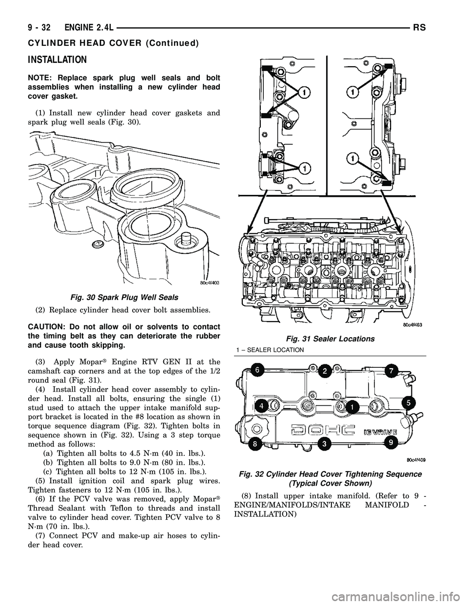
(1) Install new cylinder head cover gaskets and
spark plug well seals (Fig. 30).
(2) Replace cylinder head cover bolt assemblies.
CAUTION: Do not allow oil or solvents to contact
the timing belt as they can deteriorate the rubber
and cause tooth skipping.
(3) Apply MopartEngine RTV GEN II at the
camshaft cap corners and at the top edges of the 1/2
round seal (Fig. 31).
(4) Install cylinder head cover assembly to cylin-
der head. Install all bolts, ensuring the single (1)
stud used to attach the upper intake manifold sup-
port bracket is located in the #8 location as shown in
torque sequence diagram (Fig. 32). Tighten bolts in
sequence shown in (Fig. 32). Using a 3 step torque
method as follows:
(a) Tighten all bolts to 4.5 N´m (40 in. lbs.).
(b) Tighten all bolts to 9.0 N´m (80 in. lbs.).
(c) Tighten all bolts to 12 N´m (105 in. lbs.).
(5) Install ignition coil and spark plug wires.
Tighten fasteners to 12 N´m (105 in. lbs.).
(6) If the PCV valve was removed, apply Mopart
Thread Sealant with Teflon to threads and install
valve to cylinder head cover. Tighten PCV valve to 8
N´m (70 in. lbs.).
(7) Connect PCV and make-up air hoses to cylin-
der head cover.(8) Install upper intake manifold. (Refer to 9 -
ENGINE/MANIFOLDS/INTAKE MANIFOLD -
INSTALLATION)
Fig. 30 Spark Plug Well Seals
Fig. 31 Sealer Locations
1 ± SEALER LOCATION
Fig. 32 Cylinder Head Cover Tightening Sequence
(Typical Cover Shown)
9 - 32 ENGINE 2.4LRS
CYLINDER HEAD COVER (Continued)
Page 1210 of 2339
INTAKE/EXHAUST VALVES &
SEATS
DESCRIPTION
The valves are made of heat resistant steel. They
have chrome plated stems to prevent scuffing. Viton
rubber valve stem seals are integral with the spring
seats. The valves have three-bead lock keepers to
retain springs and to promote valve rotation.
CLEANING
(1) Clean all valves thoroughly and discard
burned, warped and cracked valves.
VALVE SPRINGS & SEALS
REMOVAL
REMOVAL - CYLINDER HEAD ON
(1) Remove cylinder head cover (Refer to 9 -
ENGINE/CYLINDER HEAD/CYLINDER HEAD
COVER(S) - REMOVAL).
(2) Remove camshafts (Refer to 9 - ENGINE/CYL-
INDER HEAD/CAMSHAFT(S) - REMOVAL).
(3) Rotate crankshaft until piston is at TDC on
compression.
(4) With air hose attached to adapter tool installed
in spark plug hole, apply 90-120 psi air pressure.
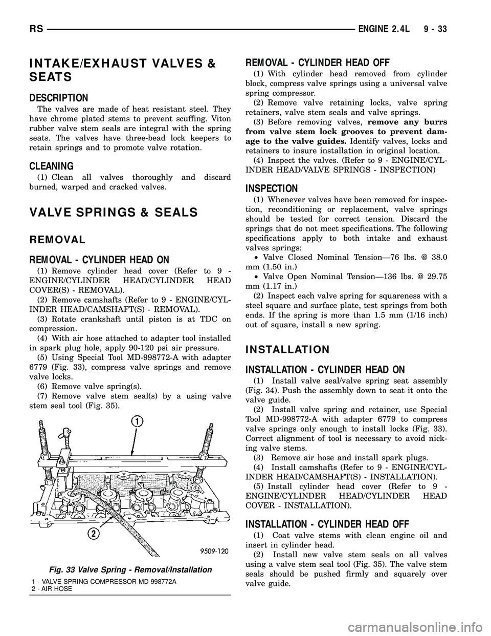
(5) Using Special Tool MD-998772-A with adapter
6779 (Fig. 33), compress valve springs and remove
valve locks.
(6) Remove valve spring(s).
(7) Remove valve stem seal(s) by a using valve
stem seal tool (Fig. 35).
REMOVAL - CYLINDER HEAD OFF
(1) With cylinder head removed from cylinder
block, compress valve springs using a universal valve
spring compressor.
(2) Remove valve retaining locks, valve spring
retainers, valve stem seals and valve springs.
(3) Before removing valves,remove any burrs
from valve stem lock grooves to prevent dam-
age to the valve guides.Identify valves, locks and
retainers to insure installation in original location.
(4) Inspect the valves. (Refer to 9 - ENGINE/CYL-
INDER HEAD/VALVE SPRINGS - INSPECTION)
INSPECTION
(1) Whenever valves have been removed for inspec-
tion, reconditioning or replacement, valve springs
should be tested for correct tension. Discard the
springs that do not meet specifications. The following
specifications apply to both intake and exhaust
valves springs:
²Valve Closed Nominal TensionÐ76 lbs. @ 38.0
mm (1.50 in.)
²Valve Open Nominal TensionÐ136 lbs. @ 29.75
mm (1.17 in.)
(2) Inspect each valve spring for squareness with a
steel square and surface plate, test springs from both
ends. If the spring is more than 1.5 mm (1/16 inch)
out of square, install a new spring.
INSTALLATION
INSTALLATION - CYLINDER HEAD ON
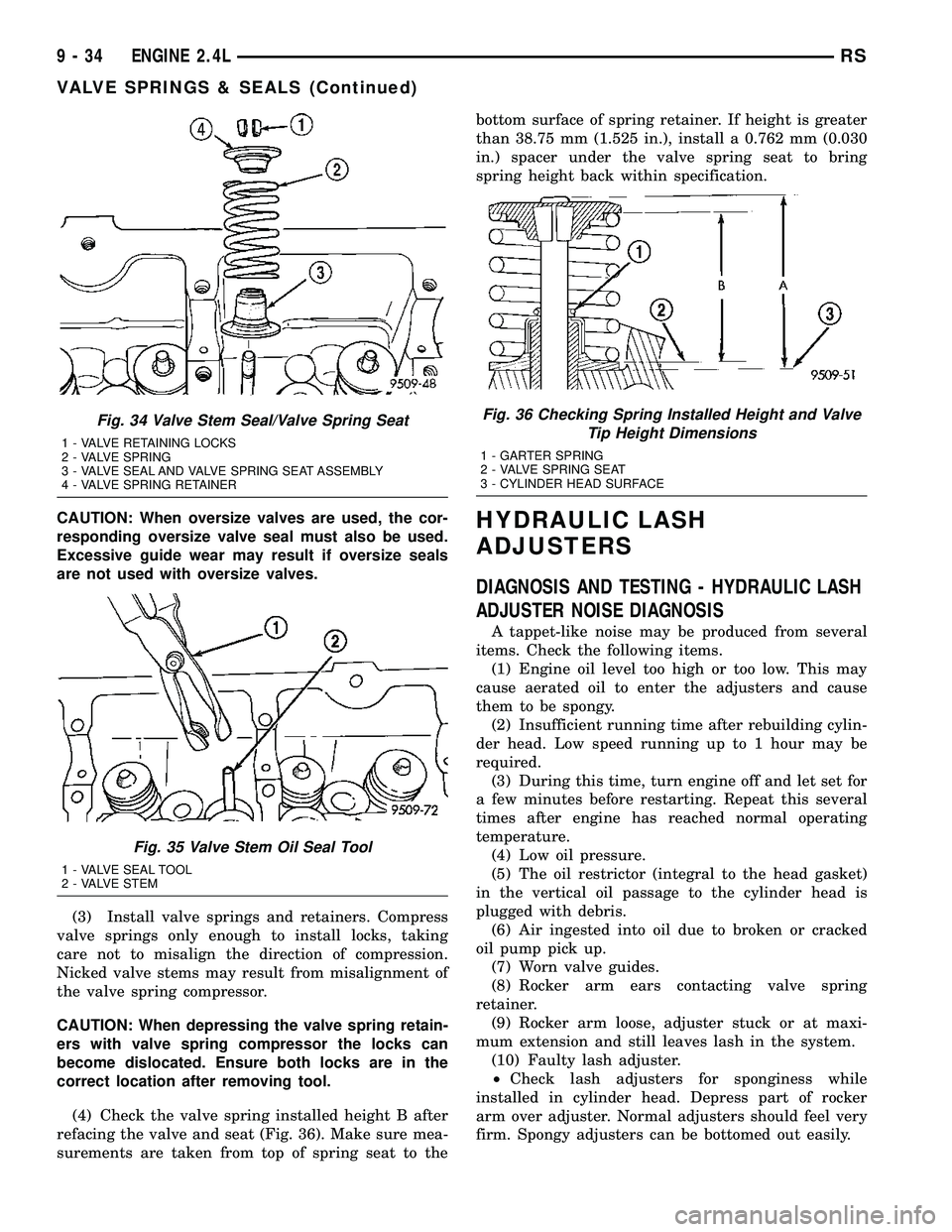
(1) Install valve seal/valve spring seat assembly
(Fig. 34). Push the assembly down to seat it onto the
valve guide.
(2) Install valve spring and retainer, use Special
Tool MD-998772-A with adapter 6779 to compress
valve springs only enough to install locks (Fig. 33).
Correct alignment of tool is necessary to avoid nick-
ing valve stems.
(3) Remove air hose and install spark plugs.
(4) Install camshafts (Refer to 9 - ENGINE/CYL-
INDER HEAD/CAMSHAFT(S) - INSTALLATION).
(5) Install cylinder head cover (Refer to 9 -
ENGINE/CYLINDER HEAD/CYLINDER HEAD
COVER - INSTALLATION).
INSTALLATION - CYLINDER HEAD OFF
(1) Coat valve stems with clean engine oil and
insert in cylinder head.
(2) Install new valve stem seals on all valves
using a valve stem seal tool (Fig. 35). The valve stem
seals should be pushed firmly and squarely over
valve guide.
Fig. 33 Valve Spring - Removal/Installation
1 - VALVE SPRING COMPRESSOR MD 998772A
2 - AIR HOSE
RSENGINE 2.4L9-33
Page 1211 of 2339
CAUTION: When oversize valves are used, the cor-
responding oversize valve seal must also be used.
Excessive guide wear may result if oversize seals
are not used with oversize valves.
(3) Install valve springs and retainers. Compress
valve springs only enough to install locks, taking
care not to misalign the direction of compression.
Nicked valve stems may result from misalignment of
the valve spring compressor.
CAUTION: When depressing the valve spring retain-
ers with valve spring compressor the locks can
become dislocated. Ensure both locks are in the
correct location after removing tool.
(4) Check the valve spring installed height B after
refacing the valve and seat (Fig. 36). Make sure mea-
surements are taken from top of spring seat to thebottom surface of spring retainer. If height is greater
than 38.75 mm (1.525 in.), install a 0.762 mm (0.030
in.) spacer under the valve spring seat to bring
spring height back within specification.HYDRAULIC LASH
ADJUSTERS
DIAGNOSIS AND TESTING - HYDRAULIC LASH
ADJUSTER NOISE DIAGNOSIS
A tappet-like noise may be produced from several
items. Check the following items.
(1) Engine oil level too high or too low. This may
cause aerated oil to enter the adjusters and cause
them to be spongy.
(2) Insufficient running time after rebuilding cylin-
der head. Low speed running up to 1 hour may be
required.
(3) During this time, turn engine off and let set for
a few minutes before restarting. Repeat this several
times after engine has reached normal operating
temperature.
(4) Low oil pressure.
(5) The oil restrictor (integral to the head gasket)
in the vertical oil passage to the cylinder head is
plugged with debris.
(6) Air ingested into oil due to broken or cracked
oil pump pick up.
(7) Worn valve guides.
(8) Rocker arm ears contacting valve spring
retainer.
(9) Rocker arm loose, adjuster stuck or at maxi-
mum extension and still leaves lash in the system.
(10) Faulty lash adjuster.
²Check lash adjusters for sponginess while
installed in cylinder head. Depress part of rocker
arm over adjuster. Normal adjusters should feel very
firm. Spongy adjusters can be bottomed out easily.
Fig. 34 Valve Stem Seal/Valve Spring Seat
1 - VALVE RETAINING LOCKS
2 - VALVE SPRING
3 - VALVE SEAL AND VALVE SPRING SEAT ASSEMBLY
4 - VALVE SPRING RETAINER
Fig. 35 Valve Stem Oil Seal Tool
1 - VALVE SEAL TOOL
2 - VALVE STEM
Fig. 36 Checking Spring Installed Height and Valve
Tip Height Dimensions
1 - GARTER SPRING
2 - VALVE SPRING SEAT
3 - CYLINDER HEAD SURFACE
9 - 34 ENGINE 2.4LRS
VALVE SPRINGS & SEALS (Continued)
Page 1216 of 2339
thrust faces of No. 3 main bearing. DO NOT nick
crank pin or bearing fillets. After grinding, remove
rough edges from crankshaft oil holes and clean out
all passages.
CAUTION: With the nodular cast iron crankshafts, it
is important that the final paper or cloth polish be
in the same direction as normal rotation in the
engine.
INSTALLATION - CRANKSHAFT
CRANKSHAFT MAIN BEARING LOCATION
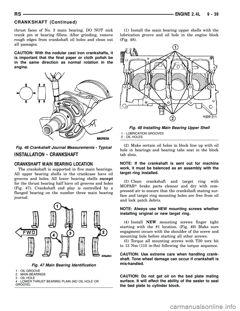
The crankshaft is supported in five main bearings.
All upper bearing shells in the crankcase have oil
grooves and holes. All lower bearing shellsexcept
for the thrust bearing half have oil grooves and holes
(Fig. 47). Crankshaft end play is controlled by a
flanged bearing on the number three main bearing
journal.(1) Install the main bearing upper shells with the
lubrication groove and oil hole in the engine block
(Fig. 48).
(2) Make certain oil holes in block line up with oil
hole in bearings and bearing tabs seat in the block
tab slots.
NOTE: If the crankshaft is sent out for machine
work, it must be balenced as an assembly with the
target ring installed.
(3) Clean crankshaft and target ring with
MOPARtbrake parts cleaner and dry with com-
pressed air to ensure that the crankshaft mating sur-
face and target ring mounting holes are free from oil
and lock patch debris.
NOTE: Always use NEW mounting screws whether
installing original or new target ring.
(4) InstallNEWmounting screws finger tight
starting with the #1 location. (Fig. 49) Make sure
engagment occurs with the shoulder of the screw and
mounting hole before starting all other screws.
(5) Torque all mounting screws with T30 torx bit
to 13 Nm (110 in-lbs) following the torque sequence.
CAUTION: Use extreme care when handling crank-
shaft. Tone wheel damage can occur if crankshaft is
mis-handled.
CAUTION: Do not get oil on the bed plate mating
surface. It will affect the ability of the sealer to seal
the bed plate to cylinder block.
Fig. 46 Crankshaft Journal Measurements - Typical
Fig. 47 Main Bearing Identification
1 - OIL GROOVE
2 - MAIN BEARINGS
3 - OIL HOLE
4 - LOWER THRUST BEARING PLAIN (NO OIL HOLE OR
GROOVE)
Fig. 48 Installing Main Bearing Upper Shell
1 - LUBRICATION GROOVES
2 - OIL HOLES
RSENGINE 2.4L9-39
CRANKSHAFT (Continued)
Page 1231 of 2339
(6) Install oil pressure switch and connector. (Refer
to 9 - ENGINE/LUBRICATION/OIL PRESSURE
SENSOR/SWITCH - INSTALLATION)
OIL
STANDARD PROCEDURE
ENGINE OIL LEVEL CHECK
The best time to check engine oil level is after it
has sat overnight, or if the engine has been running,
allow the engine to be shut off for at least 5 minutes
before checking oil level.
Checking the oil while the vehicle is on level
ground will improve the accuracy of the oil level
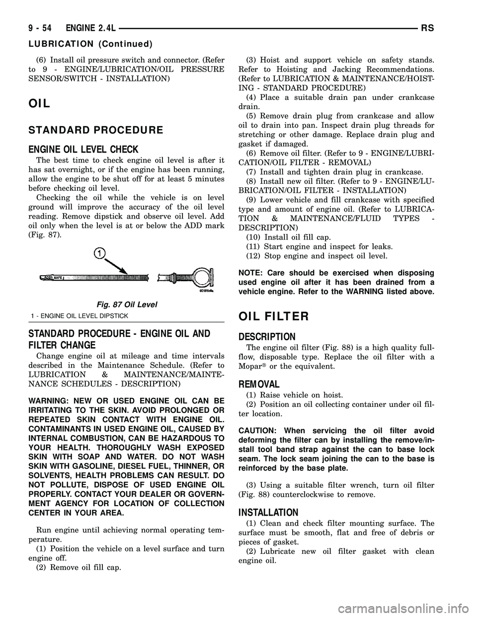
reading. Remove dipstick and observe oil level. Add
oil only when the level is at or below the ADD mark
(Fig. 87).
STANDARD PROCEDURE - ENGINE OIL AND
FILTER CHANGE
Change engine oil at mileage and time intervals
described in the Maintenance Schedule. (Refer to
LUBRICATION & MAINTENANCE/MAINTE-
NANCE SCHEDULES - DESCRIPTION)
WARNING: NEW OR USED ENGINE OIL CAN BE
IRRITATING TO THE SKIN. AVOID PROLONGED OR
REPEATED SKIN CONTACT WITH ENGINE OIL.
CONTAMINANTS IN USED ENGINE OIL, CAUSED BY
INTERNAL COMBUSTION, CAN BE HAZARDOUS TO
YOUR HEALTH. THOROUGHLY WASH EXPOSED
SKIN WITH SOAP AND WATER. DO NOT WASH
SKIN WITH GASOLINE, DIESEL FUEL, THINNER, OR
SOLVENTS, HEALTH PROBLEMS CAN RESULT. DO
NOT POLLUTE, DISPOSE OF USED ENGINE OIL
PROPERLY. CONTACT YOUR DEALER OR GOVERN-
MENT AGENCY FOR LOCATION OF COLLECTION
CENTER IN YOUR AREA.
Run engine until achieving normal operating tem-
perature.
(1) Position the vehicle on a level surface and turn
engine off.
(2) Remove oil fill cap.(3) Hoist and support vehicle on safety stands.
Refer to Hoisting and Jacking Recommendations.
(Refer to LUBRICATION & MAINTENANCE/HOIST-
ING - STANDARD PROCEDURE)
(4) Place a suitable drain pan under crankcase
drain.
(5) Remove drain plug from crankcase and allow
oil to drain into pan. Inspect drain plug threads for
stretching or other damage. Replace drain plug and
gasket if damaged.
(6) Remove oil filter. (Refer to 9 - ENGINE/LUBRI-
CATION/OIL FILTER - REMOVAL)
(7) Install and tighten drain plug in crankcase.
(8) Install new oil filter. (Refer to 9 - ENGINE/LU-
BRICATION/OIL FILTER - INSTALLATION)
(9) Lower vehicle and fill crankcase with specified
type and amount of engine oil. (Refer to LUBRICA-
TION & MAINTENANCE/FLUID TYPES -
DESCRIPTION)
(10) Install oil fill cap.
(11) Start engine and inspect for leaks.
(12) Stop engine and inspect oil level.
NOTE: Care should be exercised when disposing
used engine oil after it has been drained from a
vehicle engine. Refer to the WARNING listed above.
OIL FILTER
DESCRIPTION
The engine oil filter (Fig. 88) is a high quality full-
flow, disposable type. Replace the oil filter with a
Mopartor the equivalent.
REMOVAL
(1) Raise vehicle on hoist.
(2) Position an oil collecting container under oil fil-
ter location.
CAUTION: When servicing the oil filter avoid
deforming the filter can by installing the remove/in-
stall tool band strap against the can to base lock
seam. The lock seam joining the can to the base is
reinforced by the base plate.
(3) Using a suitable filter wrench, turn oil filter
(Fig. 88) counterclockwise to remove.
INSTALLATION
(1) Clean and check filter mounting surface. The
surface must be smooth, flat and free of debris or
pieces of gasket.
(2) Lubricate new oil filter gasket with clean
engine oil.
Fig. 87 Oil Level
1 - ENGINE OIL LEVEL DIPSTICK
9 - 54 ENGINE 2.4LRS
LUBRICATION (Continued)
Page 1232 of 2339
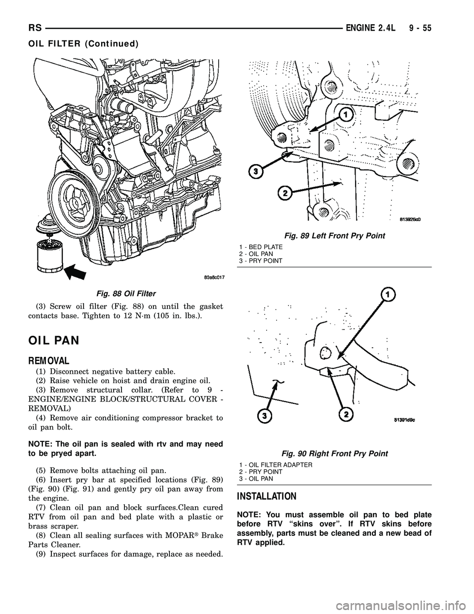
(3) Screw oil filter (Fig. 88) on until the gasket
contacts base. Tighten to 12 N´m (105 in. lbs.).
OIL PAN
REMOVAL
(1) Disconnect negative battery cable.
(2) Raise vehicle on hoist and drain engine oil.
(3) Remove structural collar. (Refer to 9 -
ENGINE/ENGINE BLOCK/STRUCTURAL COVER -
REMOVAL)
(4) Remove air conditioning compressor bracket to
oil pan bolt.
NOTE: The oil pan is sealed with rtv and may need
to be pryed apart.
(5) Remove bolts attaching oil pan.
(6) Insert pry bar at specified locations (Fig. 89)
(Fig. 90) (Fig. 91) and gently pry oil pan away from
the engine.
(7) Clean oil pan and block surfaces.Clean cured
RTV from oil pan and bed plate with a plastic or
brass scraper.
(8) Clean all sealing surfaces with MOPARtBrake
Parts Cleaner.
(9) Inspect surfaces for damage, replace as needed.
INSTALLATION
NOTE: You must assemble oil pan to bed plate
before RTV ªskins overº. If RTV skins before
assembly, parts must be cleaned and a new bead of
RTV applied.
Fig. 88 Oil Filter
Fig. 89 Left Front Pry Point
1 - BED PLATE
2 - OIL PAN
3 - PRY POINT
Fig. 90 Right Front Pry Point
1 - OIL FILTER ADAPTER
2 - PRY POINT
3 - OIL PAN
RSENGINE 2.4L9-55
OIL FILTER (Continued)
Page 1233 of 2339
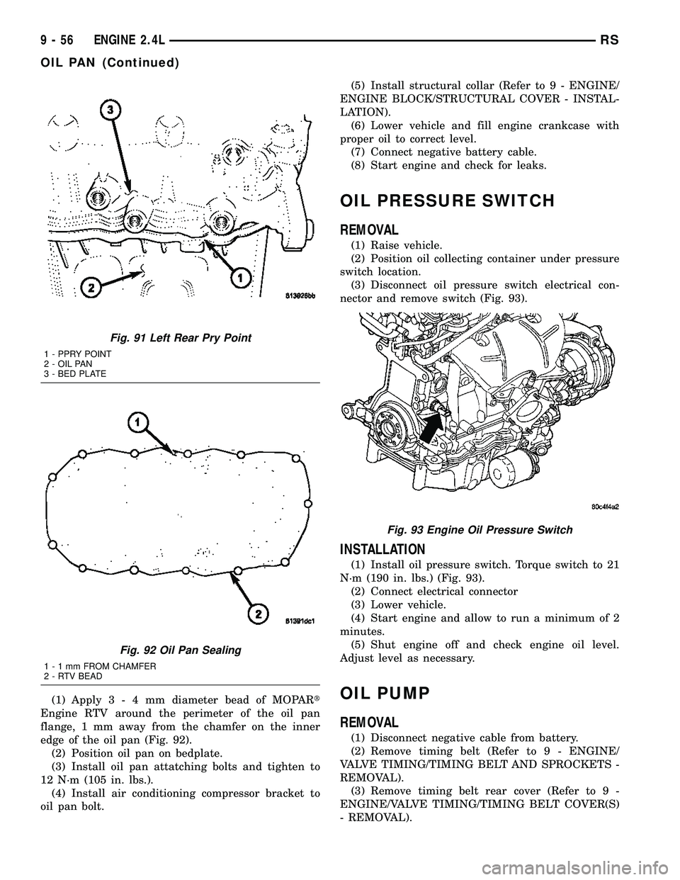
(1) Apply3-4mmdiameter bead of MOPARt
Engine RTV around the perimeter of the oil pan
flange, 1 mm away from the chamfer on the inner
edge of the oil pan (Fig. 92).
(2) Position oil pan on bedplate.
(3) Install oil pan attatching bolts and tighten to
12 N´m (105 in. lbs.).
(4) Install air conditioning compressor bracket to
oil pan bolt.(5) Install structural collar (Refer to 9 - ENGINE/
ENGINE BLOCK/STRUCTURAL COVER - INSTAL-
LATION).
(6) Lower vehicle and fill engine crankcase with
proper oil to correct level.
(7) Connect negative battery cable.
(8) Start engine and check for leaks.
OIL PRESSURE SWITCH
REMOVAL
(1) Raise vehicle.
(2) Position oil collecting container under pressure
switch location.
(3) Disconnect oil pressure switch electrical con-
nector and remove switch (Fig. 93).
INSTALLATION
(1) Install oil pressure switch. Torque switch to 21
N´m (190 in. lbs.) (Fig. 93).
(2) Connect electrical connector
(3) Lower vehicle.
(4) Start engine and allow to run a minimum of 2
minutes.
(5) Shut engine off and check engine oil level.
Adjust level as necessary.
OIL PUMP
REMOVAL
(1) Disconnect negative cable from battery.
(2) Remove timing belt (Refer to 9 - ENGINE/
VALVE TIMING/TIMING BELT AND SPROCKETS -
REMOVAL).
(3) Remove timing belt rear cover (Refer to 9 -
ENGINE/VALVE TIMING/TIMING BELT COVER(S)
- REMOVAL).
Fig. 91 Left Rear Pry Point
1 - PPRY POINT
2 - OIL PAN
3 - BED PLATE
Fig. 92 Oil Pan Sealing
1-1mmFROM CHAMFER
2 - RTV BEAD
Fig. 93 Engine Oil Pressure Switch
9 - 56 ENGINE 2.4LRS
OIL PAN (Continued)
Page 1236 of 2339
INSTALLATION
(1) Make sure all surfaces are clean and free of oil
and dirt.
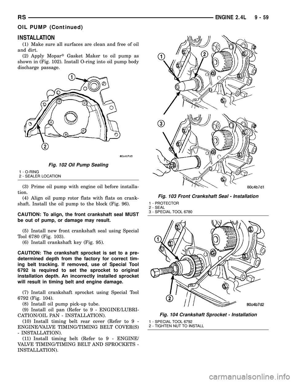
(2) Apply MopartGasket Maker to oil pump as
shown in (Fig. 102). Install O-ring into oil pump body
discharge passage.
(3) Prime oil pump with engine oil before installa-
tion.
(4) Align oil pump rotor flats with flats on crank-
shaft. Install the oil pump to the block (Fig. 96).
CAUTION: To align, the front crankshaft seal MUST
be out of pump, or damage may result.
(5) Install new front crankshaft seal using Special
Tool 6780 (Fig. 103).
(6) Install crankshaft key (Fig. 95).
CAUTION: The crankshaft sprocket is set to a pre-
determined depth from the factory for correct tim-
ing belt tracking. If removed, use of Special Tool
6792 is required to set the sprocket to original
installation depth. An incorrectly installed sprocket
will result in timing belt and engine damage.
(7) Install crankshaft sprocket using Special Tool
6792 (Fig. 104).
(8) Install oil pump pick-up tube.
(9) Install oil pan (Refer to 9 - ENGINE/LUBRI-
CATION/OIL PAN - INSTALLATION).
(10) Install timing belt rear cover (Refer to 9 -
ENGINE/VALVE TIMING/TIMING BELT COVER(S)
- INSTALLATION).
(11) Install timing belt (Refer to 9 - ENGINE/
VALVE TIMING/TIMING BELT AND SPROCKETS -
INSTALLATION).
Fig. 102 Oil Pump Sealing
1 - O-RING
2 - SEALER LOCATION
Fig. 103 Front Crankshaft Seal - Installation
1 - PROTECTOR
2 - SEAL
3 - SPECIAL TOOL 6780
Fig. 104 Crankshaft Sprocket - Installation
1 - SPECIAL TOOL 6792
2 - TIGHTEN NUT TO INSTALL
RSENGINE 2.4L9-59
OIL PUMP (Continued)