2005 CHRYSLER CARAVAN fuel
[x] Cancel search: fuelPage 1958 of 2339
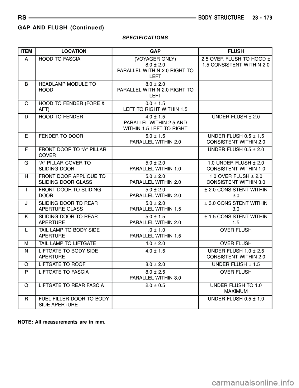
SPECIFICATIONS
ITEM LOCATION GAP FLUSH
A HOOD TO FASCIA (VOYAGER ONLY)
8.0 2.0
PARALLEL WITHIN 2.0 RIGHT TO
LEFT2.5 OVER FLUSH TO HOOD
1.5 CONSISTENT WITHIN 2.0
B HEADLAMP MODULE TO
HOOD8.0 2.0
PARALLEL WITHIN 2.0 RIGHT TO
LEFT
C HOOD TO FENDER (FORE &
AFT)0.0 1.5
LEFT TO RIGHT WITHIN 1.5
D HOOD TO FENDER 4.0 1.5
PARALLEL WITHIN 2.5 AND
WITHIN 1.5 LEFT TO RIGHTUNDER FLUSH 2.0
E FENDER TO DOOR 5.0 1.5
PARALLEL WITHIN 2.0UNDER FLUSH 0.5 1.5
CONSISTENT WITHIN 2.0
F FRONT DOOR TO9A9PILLAR
COVERUNDER FLUSH 0.5 2.0
G9A9PILLAR COVER TO
SLIDING DOOR5.0 2.0
PARALLEL WITHIN 1.01.0 UNDER FLUSH 2.0
CONSISTENT WITHIN 1.0
H FRONT DOOR APPLIQUE TO
SLIDING DOOR GLASS5.0 2.0
PARALLEL WITHIN 2.01.0 OVER FLUSH 2.0
CONSISTENT WITHIN 3.0
I FRONT DOOR TO SLIDING
DOOR5.0 2.0
PARALLEL WITHIN 2.0 2.0 CONSISTENT WITHIN
2.0
J SLIDING DOOR TO REAR
APERTURE GLASS5.0 2.0
PARALLEL WITHIN 1.5 3.0 CONSISTENT WITHIN
3.0
K SLIDING DOOR TO REAR
APERTURE5.0 1.5
PARALLEL WITHIN 2.0 1.5 CONSISTENT WITHIN
1.5
L TAIL LAMP TO BODY SIDE
APERTURE1.0 1.0
PARALLEL WITHIN 1.5OVER FLUSH
M TAIL LAMP TO LIFTGATE 4.0 2.0 OVER FLUSH
N LIFTGATE TO BODY SIDE
APERTURE4.0 1.5 UNDER FLUSH 1.0 2.5
CONSISTENT WITHIN 2.0
O LIFTGATE TO ROOF 8.0 2.0 UNDER FLUSH 1.5
P LIFTGATE TO FASCIA 8.0 2.5
PARALLEL WITHIN 3.0OVER FLUSH
Q LIFTGATE TO REAR FASCIA 2.0 0.5 UNDER FLUSH TO 1.0
MAXIMUM
R FUEL FILLER DOOR TO BODY
SIDE APERTUREUNDER FLUSH 0.5 1.0
NOTE: All measurements are in mm.
RSBODY STRUCTURE23 - 179
GAP AND FLUSH (Continued)
Page 2013 of 2339
WELD LOCATIONS
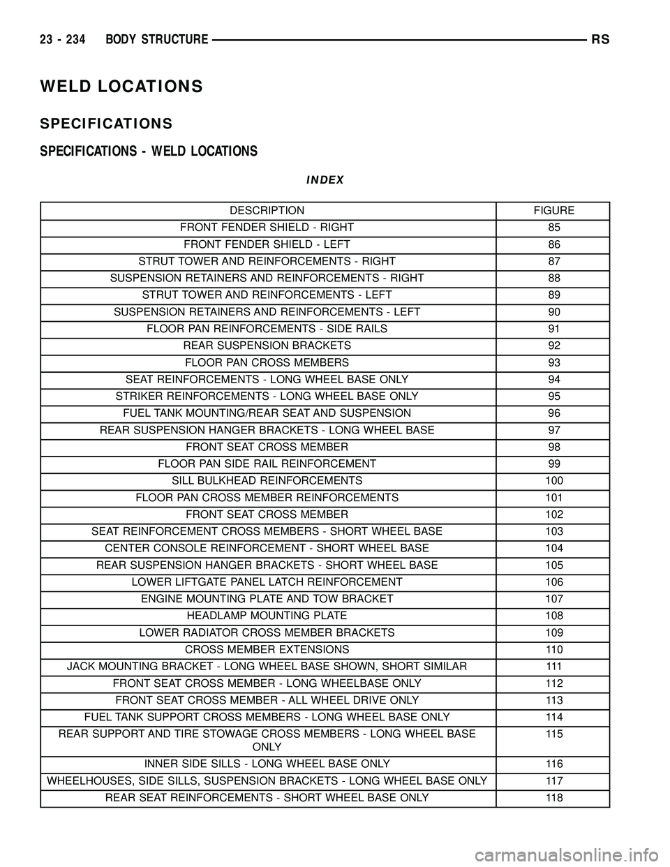
SPECIFICATIONS
SPECIFICATIONS - WELD LOCATIONS
INDEX
DESCRIPTION FIGURE
FRONT FENDER SHIELD - RIGHT 85
FRONT FENDER SHIELD - LEFT 86
STRUT TOWER AND REINFORCEMENTS - RIGHT 87
SUSPENSION RETAINERS AND REINFORCEMENTS - RIGHT 88
STRUT TOWER AND REINFORCEMENTS - LEFT 89
SUSPENSION RETAINERS AND REINFORCEMENTS - LEFT 90
FLOOR PAN REINFORCEMENTS - SIDE RAILS 91
REAR SUSPENSION BRACKETS 92
FLOOR PAN CROSS MEMBERS 93
SEAT REINFORCEMENTS - LONG WHEEL BASE ONLY 94
STRIKER REINFORCEMENTS - LONG WHEEL BASE ONLY 95
FUEL TANK MOUNTING/REAR SEAT AND SUSPENSION 96
REAR SUSPENSION HANGER BRACKETS - LONG WHEEL BASE 97
FRONT SEAT CROSS MEMBER 98
FLOOR PAN SIDE RAIL REINFORCEMENT 99
SILL BULKHEAD REINFORCEMENTS 100
FLOOR PAN CROSS MEMBER REINFORCEMENTS 101
FRONT SEAT CROSS MEMBER 102
SEAT REINFORCEMENT CROSS MEMBERS - SHORT WHEEL BASE 103
CENTER CONSOLE REINFORCEMENT - SHORT WHEEL BASE 104
REAR SUSPENSION HANGER BRACKETS - SHORT WHEEL BASE 105
LOWER LIFTGATE PANEL LATCH REINFORCEMENT 106
ENGINE MOUNTING PLATE AND TOW BRACKET 107
HEADLAMP MOUNTING PLATE 108
LOWER RADIATOR CROSS MEMBER BRACKETS 109
CROSS MEMBER EXTENSIONS 110
JACK MOUNTING BRACKET - LONG WHEEL BASE SHOWN, SHORT SIMILAR 111
FRONT SEAT CROSS MEMBER - LONG WHEELBASE ONLY 112
FRONT SEAT CROSS MEMBER - ALL WHEEL DRIVE ONLY 113
FUEL TANK SUPPORT CROSS MEMBERS - LONG WHEEL BASE ONLY 114
REAR SUPPORT AND TIRE STOWAGE CROSS MEMBERS - LONG WHEEL BASE
ONLY11 5
INNER SIDE SILLS - LONG WHEEL BASE ONLY 116
WHEELHOUSES, SIDE SILLS, SUSPENSION BRACKETS - LONG WHEEL BASE ONLY 117
REAR SEAT REINFORCEMENTS - SHORT WHEEL BASE ONLY 118
23 - 234 BODY STRUCTURERS
Page 2014 of 2339
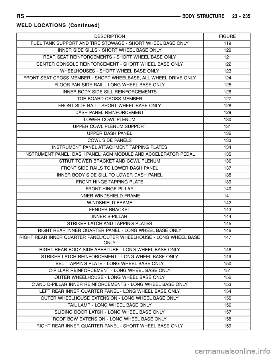
DESCRIPTION FIGURE
FUEL TANK SUPPORT AND TIRE STOWAGE - SHORT WHEEL BASE ONLY 119
INNER SIDE SILLS - SHORT WHEEL BASE ONLY 120
REAR SEAT REINFORCEMENTS - SHORT WHEEL BASE ONLY 121
CENTER CONSOLE REINFORCEMENT - SHORT WHEEL BASE ONLY 122
WHEELHOUSES - SHORT WHEEL BASE ONLY 123
FRONT SEAT CROSS MEMBER - SHORT WHEELBASE, ALL WHEEL DRIVE ONLY 124
FLOOR PAN SIDE RAIL - LONG WHEEL BASE ONLY 125
INNER BODY SIDE SILL REINFORCEMENTS 126
TOE BOARD CROSS MEMBER 127
FRONT SIDE RAIL - SHORT WHEEL BASE ONLY 128
DASH PANEL REINFORCEMENT 129
LOWER COWL PLENUM 130
UPPER COWL PLENUM SUPPORT 131
UPPER DASH PANEL 132
COWL SIDE PANELS 133
INSTRUMENT PANEL ATTACHMENT TAPPING PLATES 134
INSTRUMENT PANEL, DASH PANEL, ACM MODULE AND ACCELERATOR PEDAL 135
STRUT TOWER BRACKET AND COWL PLENUM 136
FRONT SIDE RAILS TO LOWER DASH PANEL 137
INNER BODY SIDE SILL TO LOWER DASH PANEL 138
FRONT HINGE TAPPING PLATE 139
FRONT HINGE PILLAR 140
INNER WINDSHIELD FRAME 141
WINDSHIELD FRAME 142
FENDER BRACKET 143
INNER B-PILLAR 144
STRIKER LATCH AND TAPPING PLATES 145
RIGHT REAR INNER QUARTER PANEL - LONG WHEEL BASE ONLY 146
RIGHT REAR INNER QUARTER PANEL/OUTER WHEELHOUSE - LONG WHEEL BASE
ONLY147
RIGHT REAR BODY SIDE APERTURE - LONG WHEEL BASE ONLY 148
STRIKER LATCH REINFORCEMENT - LONG WHEEL BASE ONLY 149
BELT TAPPING PLATE - LONG WHEEL BASE ONLY 150
C-PILLAR REINFORCEMENT - LONG WHEEL BASE ONLY 151
OUTER WHEELHOUSE - LONG WHEEL BASE ONLY 152
C AND D-PILLAR INNER REINFORCEMENTS - LONG WHEEL BASE ONLY 153
LEFT REAR INNER QUARTER PANEL - LONG WHEEL BASE ONLY 154
OUTER WHEELHOUSE EXTENSION - LONG WHEEL BASE ONLY 155
TAIL LAMP - LONG WHEEL BASE ONLY 156
SLIDING DOOR LATCH - LONG WHEEL BASE ONLY 157
ROOF BOW EXTENSION - LONG WHEEL BASE ONLY 158
RIGHT REAR INNER QUARTER PANEL - SHORT WHEEL BASE ONLY 159
RSBODY STRUCTURE23 - 235
WELD LOCATIONS (Continued)
Page 2027 of 2339
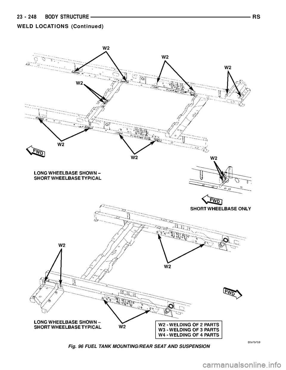
Fig. 96 FUEL TANK MOUNTING/REAR SEAT AND SUSPENSION
23 - 248 BODY STRUCTURERS
WELD LOCATIONS (Continued)
Page 2044 of 2339
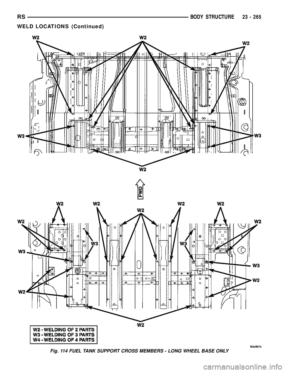
Fig. 114 FUEL TANK SUPPORT CROSS MEMBERS - LONG WHEEL BASE ONLY
RSBODY STRUCTURE23 - 265
WELD LOCATIONS (Continued)
Page 2048 of 2339
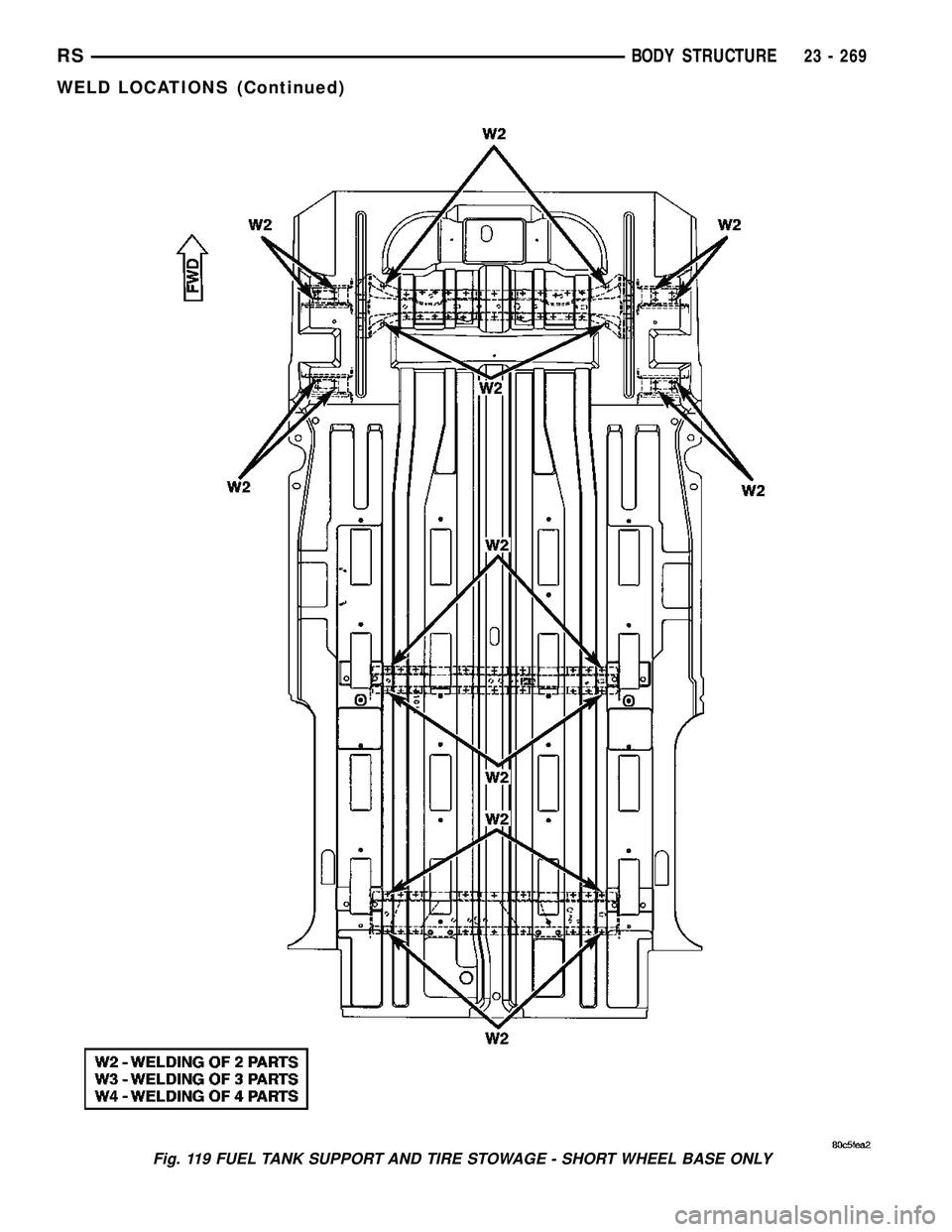
Fig. 119 FUEL TANK SUPPORT AND TIRE STOWAGE - SHORT WHEEL BASE ONLY
RSBODY STRUCTURE23 - 269
WELD LOCATIONS (Continued)
Page 2264 of 2339
CABIN HEATER
TABLE OF CONTENTS
page page
CABIN HEATER
DESCRIPTION........................113
OPERATION
MANUAL TEMPERATURE CONTROL
SYSTEM...........................113
AUTOMATIC TEMPERATURE CONTROL
SYSTEM...........................114
WARNING............................114
DIAGNOSIS AND TESTING
SUPPLEMENTAL CABIN HEATER........114
AIR INTAKE PIPE
REMOVAL............................115
INSTALLATION........................115
EXHAUST TUBE
REMOVAL............................116
INSTALLATION........................116
FUEL DOSING PUMP
DESCRIPTION........................117
OPERATION..........................117REMOVAL............................117
INSTALLATION........................117
FUEL LINE
STANDARD PROCEDURE
CLEANING..........................118
REMOVAL............................118
INSTALLATION........................118
HEATER HOSES
REMOVAL............................119
INSTALLATION........................119
HEATER PIPES
REMOVAL............................119
INSTALLATION........................120
HEATER UNIT
REMOVAL............................121
INSTALLATION........................122
HEATER WIRING
REMOVAL............................122
INSTALLATION........................122
CABIN HEATER
DESCRIPTION
Vehicles equipped with the diesel engine are also
equipped with a supplemental cabin heater. This
cabin heater is mounted under the vehicle and oper-
ates similar to an oil fired furnace. The heater burns
small amounts of fuel to provide additional heat to
the coolant. Coolant is routed from the engine, to the
supplemental cabin heater and then to the front
heater core. This provides additional heat to the pas-
senger compartment. The supplemental cabin heater
system is interfaced to the vehicles on-board com-
puter systems and DRBIIItdiagnostics.
The supplemental cabin heater has an electronic
control module that monitors the heat output of the
heater. The cabin heater operates at full load (5 kW),
half load or idle mode (no additional heat) depending
on engine coolant temperature.
When ambient temperatures are lower than 15É C
(60É F), the supplemental cabin heater automatically
operates once each ignition cycle for five minutes.
This assures a good fuel supply is always present for
the supplemental cabin heater.
OPERATION
MANUAL TEMPERATURE CONTROL SYSTEM
The supplemental cabin heater is activated via the
temperature slide control or knob on the A/C-heater
control when equipped with the manual temperature
control (MTC) system. If the slide control or knob is
moved to or above the upper set point the cabin
heater is activated. The cabin heater can operate in a
full or partial load range as well as an idle mode all
dependent on the engine coolant temperature. The
cabin heater will also turn off if the A/C-heater tem-
perature control is lowered to less than the lower set
point. The cabin heater can take up to three minutes
to completely shut down when either the heater tem-
perature is set below the lower set point or the vehi-
cle ignition is shut down.
NOTE: Do not apply a strong vacuum source such
as a garage ventilation system directly on the sup-
plemental cabin heater exhaust line. Too strong of a
vacuum can prevent the supplemental cabin heater
from starting. If required, place the vacuum source
at least 75 mm (3 in.) away from the exhaust line.
RSCABIN HEATER24 - 113
Page 2265 of 2339
The supplemental cabin heater only operates when
the engine is running, the mileage exceeds 8 kilome-
ter (5 mph) and the fuel tank volume exceeds 1/8 of a
tank. The supplemental heater control module moni-
tors blower speed and combustion during its start-up.
The cabin heater should operate if the coolant tem-
perature is below 40É C (104É F).
AUTOMATIC TEMPERATURE CONTROL
SYSTEM
The automatic temperature control (ATC) system
will activate the supplemental cabin heater based on
engine coolant temperature and interior component
settings. The cabin heater can operate in a full or
partial load range as well as an idle mode all depen-
dent on the engine coolant temperature. The cabin
heater will also turn off if the A/C-heater tempera-
ture control is lowered to less than the lower set
point. The cabin heater can take up to three minutes
to completely shut down when either the heater tem-
perature is set below the lower set point or the vehi-
cle ignition is shut down.
NOTE: Do not apply a strong vacuum source such
as a garage ventilation system directly on the sup-
plemental cabin heater exhaust line. Too strong of a
vacuum can prevent the supplemental cabin heater
from starting. If required, place the vacuum source
at least 75 mm (3 in.) away from the exhaust line.
The supplemental cabin heater only operates when
the engine is running, the mileage exceeds 8 kilome-ter (5 mph) and the fuel tank volume exceeds 1/8 of a
tank. The supplemental heater control module moni-
tors blower speed and combustion during its start-up.
The cabin heater should operate if the coolant tem-
perature is below 40É C (104É F).
WARNING
WARNING: DO NOT OPERATE THE DIESEL SUP-
PLEMENTAL CABIN HEATER IN AN ENCLOSED
AREA SUCH AS A GARAGE THAT DOES NOT HAVE
EXHAUST VENTILATION FACILITIES. ALWAYS VENT
THE CABIN HEATER EXHAUST WHEN OPERATING
THE CABIN HEATER. ALLOW THE DIESEL SUPPLE-
MENTAL CABIN HEATER TO COOL BEFORE PER-
FORMING ANY SERVICE PROCEDURES TO THE
CABIN HEATER. VERIFY THAT ALL DIESEL SUP-
PLEMENTAL CABIN HEATER FUEL LINES ARE
SECURELY FASTENED TO THEIR RESPECTIVE
COMPONENTS BEFORE PERFORMING ANY SER-
VICE PROCEDURES TO THE CABIN HEATER. FAIL-
URE TO FOLLOW THESE INSTRUCTION MAY
RESULT IN PERSONAL INJURY OR DEATH.
DIAGNOSIS AND TESTING
SUPPLEMENTAL CABIN HEATER
Refer to the Symptoms Diagnosis table for basic
checks of the diesel fueled supplemental cabin heater.
SYMPTOMS DIAGNOSIS
Symptom Possible Causes
Smell of diesel fuel. Check cabin heater system integration in vehicle's fuel system. Check
fuel lines for leakage, kinks or obstructions. If OK, Inspect the inlet
muffler, drain as necessary. Re-test the cabin heater and re-inspect.
Inspect the exhaust tube and cabin heater for the presence of external
fuel. If presence of external fuel is observed on the heater unit or in the
exhaust tube or after draining and testing. Remove the cabin heater
from vehicle and repair or replace components as required.
Heater does not achieve full load
operation.Check cabin heater operation with DRBIIITscan tool and replace
components as required.
Continuous white smoke from heater
exhaust during combustion operation.Check cabin heater operation with DRBIIITscan tool and replace
components as required. White smoke is typical in extreme weather
conditions.
Heater can not be switched off. Check cabin heater operation with DRBIIITscan tool and replace
components as required.
Heater does not operate. Diagnosis cabin heater control module using the DRBIIITscan tool and
the procedures listed in Vehicle Performance under Cabin Heater
Diagnosis in Group 18.
24 - 114 CABIN HEATERRS
CABIN HEATER (Continued)