2005 CHRYSLER CARAVAN load capacity
[x] Cancel search: load capacityPage 318 of 2339

twenty amperes or more will require a shorter charg-
ing time.
²State-Of-Charge- A completely discharged bat-
tery requires more charging time than a partially
discharged battery. Electrolyte is nearly pure water
in a completely discharged battery. At first, the
charging current (amperage) will be low. As the bat-
tery charges, the specific gravity of the electrolyte
will gradually rise.
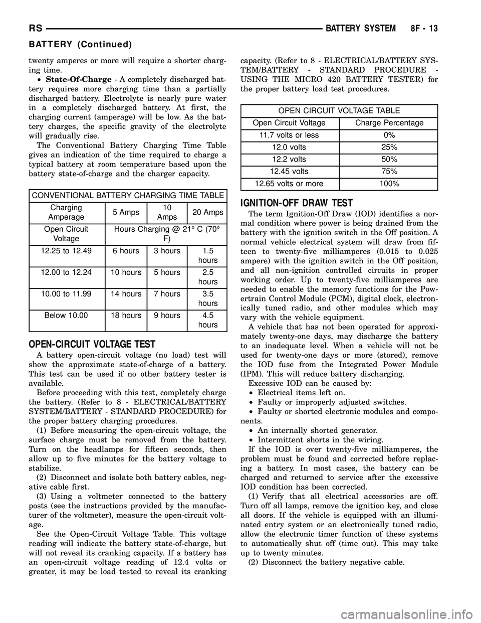
The Conventional Battery Charging Time Table
gives an indication of the time required to charge a
typical battery at room temperature based upon the
battery state-of-charge and the charger capacity.
CONVENTIONAL BATTERY CHARGING TIME TABLE
Charging
Amperage5 Amps10
Amps20 Amps
Open Circuit
VoltageHours Charging @ 21É C (70É
F)
12.25 to 12.49 6 hours 3 hours 1.5
hours
12.00 to 12.24 10 hours 5 hours 2.5
hours
10.00 to 11.99 14 hours 7 hours 3.5
hours
Below 10.00 18 hours 9 hours 4.5
hours
OPEN-CIRCUIT VOLTAGE TEST
A battery open-circuit voltage (no load) test will
show the approximate state-of-charge of a battery.
This test can be used if no other battery tester is
available.
Before proceeding with this test, completely charge
the battery. (Refer to 8 - ELECTRICAL/BATTERY
SYSTEM/BATTERY - STANDARD PROCEDURE) for
the proper battery charging procedures.
(1) Before measuring the open-circuit voltage, the
surface charge must be removed from the battery.
Turn on the headlamps for fifteen seconds, then
allow up to five minutes for the battery voltage to
stabilize.
(2) Disconnect and isolate both battery cables, neg-
ative cable first.
(3) Using a voltmeter connected to the battery
posts (see the instructions provided by the manufac-
turer of the voltmeter), measure the open-circuit volt-
age.
See the Open-Circuit Voltage Table. This voltage
reading will indicate the battery state-of-charge, but
will not reveal its cranking capacity. If a battery has
an open-circuit voltage reading of 12.4 volts or
greater, it may be load tested to reveal its crankingcapacity. (Refer to 8 - ELECTRICAL/BATTERY SYS-
TEM/BATTERY - STANDARD PROCEDURE -
USING THE MICRO 420 BATTERY TESTER) for
the proper battery load test procedures.
OPEN CIRCUIT VOLTAGE TABLE
Open Circuit Voltage Charge Percentage
11.7 volts or less 0%
12.0 volts 25%
12.2 volts 50%
12.45 volts 75%
12.65 volts or more 100%
IGNITION-OFF DRAW TEST
The term Ignition-Off Draw (IOD) identifies a nor-
mal condition where power is being drained from the
battery with the ignition switch in the Off position. A
normal vehicle electrical system will draw from fif-
teen to twenty-five milliamperes (0.015 to 0.025
ampere) with the ignition switch in the Off position,
and all non-ignition controlled circuits in proper
working order. Up to twenty-five milliamperes are
needed to enable the memory functions for the Pow-
ertrain Control Module (PCM), digital clock, electron-
ically tuned radio, and other modules which may
vary with the vehicle equipment.
A vehicle that has not been operated for approxi-
mately twenty-one days, may discharge the battery
to an inadequate level. When a vehicle will not be
used for twenty-one days or more (stored), remove
the IOD fuse from the Integrated Power Module
(IPM). This will reduce battery discharging.
Excessive IOD can be caused by:
²Electrical items left on.
²Faulty or improperly adjusted switches.
²Faulty or shorted electronic modules and compo-
nents.
²An internally shorted generator.
²Intermittent shorts in the wiring.
If the IOD is over twenty-five milliamperes, the
problem must be found and corrected before replac-
ing a battery. In most cases, the battery can be
charged and returned to service after the excessive
IOD condition has been corrected.
(1) Verify that all electrical accessories are off.
Turn off all lamps, remove the ignition key, and close
all doors. If the vehicle is equipped with an illumi-
nated entry system or an electronically tuned radio,
allow the electronic timer function of these systems
to automatically shut off (time out). This may take
up to twenty minutes.
(2) Disconnect the battery negative cable.
RSBATTERY SYSTEM8F-13
BATTERY (Continued)
Page 336 of 2339

STARTING
TABLE OF CONTENTS
page page
STARTING
DESCRIPTION.........................31
OPERATION...........................31
DIAGNOSIS AND TESTING
DIAGNOSIS AND TESTING - STARTING
SYSTEM TEST.......................31
DIAGNOSIS AND TESTING - CONTROL
CIRCUIT TEST........................33
DIAGNOSIS AND TESTING - FEED CIRCUIT
RESISTANCE TEST....................35
DIAGNOSIS AND TESTING - FEED CIRCUIT
TEST...............................36SPECIFICATIONS
Torques.............................36
STARTER ...........................37
STARTER MOTOR
REMOVAL
REMOVAL - 2.4L......................37
REMOVAL - 3.3/3.8L...................38
REMOVAL - 2.5L......................38
INSTALLATION
INSTALLATION - 2.4L..................39
INSTALLATION - 3.3/3.8L................39
INSTALLATION - 2.5L..................39
STARTING
DESCRIPTION
The starting system consists of:
²Starter relay
²Starter motor (including an integral starter sole-
noid)
Other components to be considered as part of start-
ing system are:
²Battery
²Battery cables
²Ignition switch and key lock cylinder
²Clutch pedal position switch (manual transmis-
sion)
²Park/neutral position switch (automatic trans-
mission)
²Wire harnesses and connections.
The Battery, Starting, and Charging systems oper-
ate in conjunction with one another, and must be
tested as a complete system. For correct operation of
starting/charging systems, all components used in
these 3 systems must perform within specifications.
When attempting to diagnose any of these systems, it
is important that you keep their interdependency in
mind.
The diagnostic procedures used in each of these
groups include the most basic conventional diagnostic
methods, to the more sophisticated On-Board Diag-
nostics (OBD) built into the Powertrain Control Mod-
ule (PCM). Use of an induction-type milliampere
ammeter, volt/ohmmeter, battery charger, carbon pile
rheostat (load tester), and 12-volt test lamp may be
required.
OPERATION
These components form two separate circuits. A
high amperage circuit that feeds the starter motor up
to 300+ amps, and a control circuit that operates on
less than 20 amps.
The PCM controls a double start over-ride safety
that does not allow the starter to be engaged if the
engine is already running.
DIAGNOSIS AND TESTING
DIAGNOSIS AND TESTING - STARTING
SYSTEM TEST
For circuit descriptions and diagrams, refer to the
Wiring Diagrams.
WARNING: ON VEHICLES EQUIPPED WITH AIR-
BAGS, REFER TO THE PASSIVE RESTRAINT SYS-
TEMS BEFORE ATTEMPTING STEERING WHEEL,
STEERING COLUMN, OR INSTRUMENT PANEL
COMPONENT DIAGNOSIS OR SERVICE. FAILURE
TO TAKE THE PROPER PRECAUTIONS COULD
RESULT IN ACCIDENTAL AIRBAG DEPLOYMENT
AND POSSIBLE PERSONAL INJURY.
INSPECTION
Before removing any unit from the starting system
for repair or diagnosis, perform the following inspec-
tions:
²Battery- Visually inspect the battery for indi-
cations of physical damage and loose or corroded
cable connections. Determine the state-of-charge and
cranking capacity of the battery. Charge or replace
RSSTARTING8F-31
Page 1774 of 2339

Inflation pressures specified on the Tire Inflation
Pressure Label are always the cold inflation pressure
of the tire. Cold inflation pressure is obtained after
the vehicle has not been operated for at least 3
hours, or the vehicle is driven less than one mile
after being inoperative for 3 hours. Tire inflation
pressures may increase from 2 to 6 pounds per
square inch (psi) (14 to 41 kPa) during operation. Do
not reduce this normal pressure buildup.
Improper inflation can cause:
²Uneven wear patterns
²Reduced tread life
²Reduced fuel economy
²Unsatisfactory ride
²The vehicle to drift.
WARNING: OVER OR UNDER INFLATED TIRES CAN
AFFECT VEHICLE HANDLING. THE TIRE CAN FAIL
SUDDENLY, RESULTING IN LOSS OF VEHICLE
CONTROL.
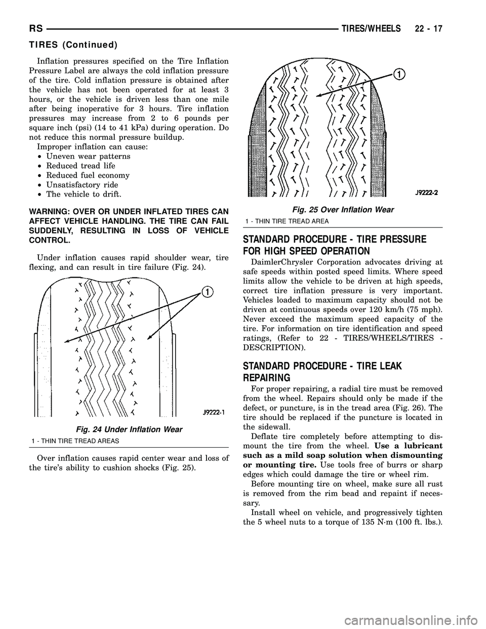
Under inflation causes rapid shoulder wear, tire
flexing, and can result in tire failure (Fig. 24).
Over inflation causes rapid center wear and loss of
the tire's ability to cushion shocks (Fig. 25).
STANDARD PROCEDURE - TIRE PRESSURE
FOR HIGH SPEED OPERATION
DaimlerChrysler Corporation advocates driving at
safe speeds within posted speed limits. Where speed
limits allow the vehicle to be driven at high speeds,
correct tire inflation pressure is very important.
Vehicles loaded to maximum capacity should not be
driven at continuous speeds over 120 km/h (75 mph).
Never exceed the maximum speed capacity of the
tire. For information on tire identification and speed
ratings, (Refer to 22 - TIRES/WHEELS/TIRES -
DESCRIPTION).
STANDARD PROCEDURE - TIRE LEAK
REPAIRING
For proper repairing, a radial tire must be removed
from the wheel. Repairs should only be made if the
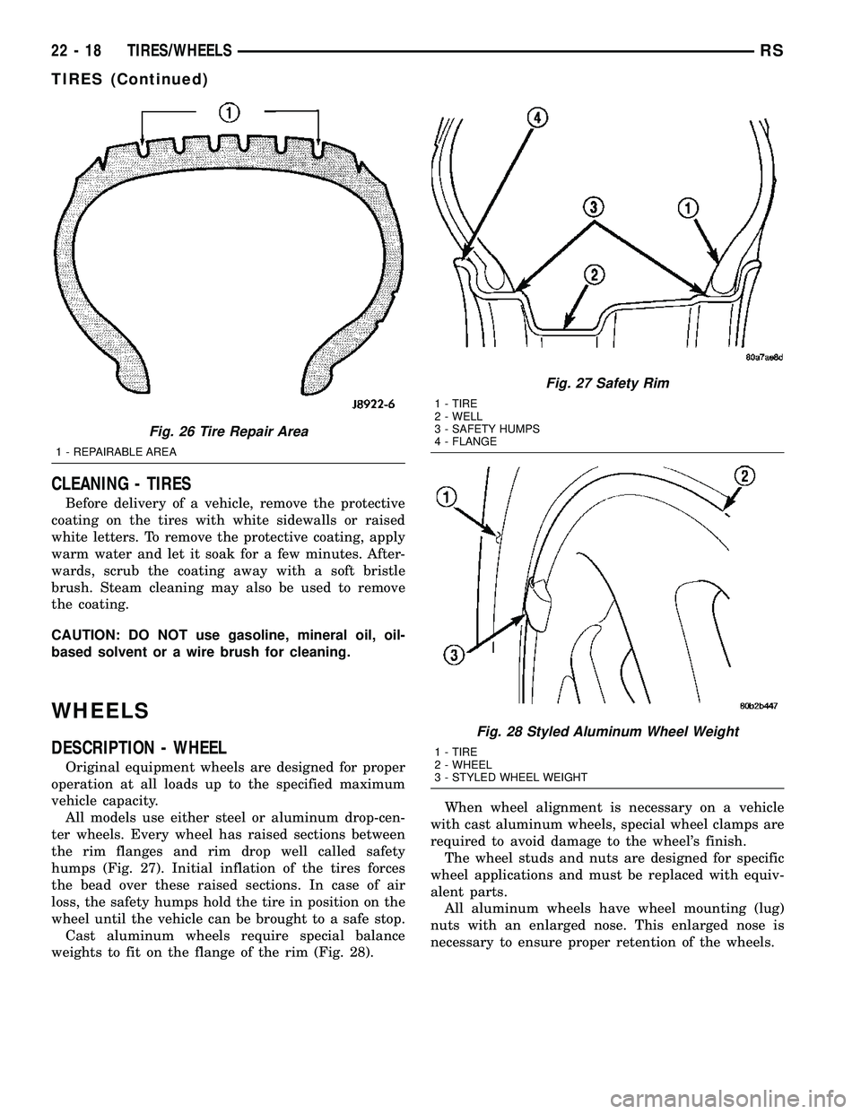
defect, or puncture, is in the tread area (Fig. 26). The
tire should be replaced if the puncture is located in
the sidewall.
Deflate tire completely before attempting to dis-
mount the tire from the wheel.Use a lubricant
such as a mild soap solution when dismounting
or mounting tire.Use tools free of burrs or sharp
edges which could damage the tire or wheel rim.
Before mounting tire on wheel, make sure all rust
is removed from the rim bead and repaint if neces-
sary.
Install wheel on vehicle, and progressively tighten
the 5 wheel nuts to a torque of 135 N´m (100 ft. lbs.).
Fig. 24 Under Inflation Wear
1 - THIN TIRE TREAD AREAS
Fig. 25 Over Inflation Wear
1 - THIN TIRE TREAD AREA
RSTIRES/WHEELS22-17
TIRES (Continued)
Page 1775 of 2339

CLEANING - TIRES
Before delivery of a vehicle, remove the protective
coating on the tires with white sidewalls or raised
white letters. To remove the protective coating, apply
warm water and let it soak for a few minutes. After-
wards, scrub the coating away with a soft bristle
brush. Steam cleaning may also be used to remove
the coating.
CAUTION: DO NOT use gasoline, mineral oil, oil-
based solvent or a wire brush for cleaning.
WHEELS
DESCRIPTION - WHEEL
Original equipment wheels are designed for proper
operation at all loads up to the specified maximum
vehicle capacity.
All models use either steel or aluminum drop-cen-
ter wheels. Every wheel has raised sections between
the rim flanges and rim drop well called safety
humps (Fig. 27). Initial inflation of the tires forces
the bead over these raised sections. In case of air
loss, the safety humps hold the tire in position on the
wheel until the vehicle can be brought to a safe stop.
Cast aluminum wheels require special balance
weights to fit on the flange of the rim (Fig. 28).When wheel alignment is necessary on a vehicle
with cast aluminum wheels, special wheel clamps are
required to avoid damage to the wheel's finish.
The wheel studs and nuts are designed for specific
wheel applications and must be replaced with equiv-
alent parts.
All aluminum wheels have wheel mounting (lug)
nuts with an enlarged nose. This enlarged nose is
necessary to ensure proper retention of the wheels.
Fig. 26 Tire Repair Area
1 - REPAIRABLE AREA
Fig. 27 Safety Rim
1 - TIRE
2 - WELL
3 - SAFETY HUMPS
4 - FLANGE
Fig. 28 Styled Aluminum Wheel Weight
1 - TIRE
2 - WHEEL
3 - STYLED WHEEL WEIGHT
22 - 18 TIRES/WHEELSRS
TIRES (Continued)
Page 1776 of 2339

DIAGNOSIS AND TESTING - WHEEL
INSPECTION
Inspect wheels for:
²Excessive runout
²Dents, cracks or irregular bends
²Damaged wheel stud (lug) holes
²Air Leaks
NOTE: Do not attempt to repair a wheel by hammer-
ing, heating or welding.
If a wheel is damaged, an original equipment
replacement wheel should be used. When obtaining
replacement wheels, they must be equivalent in load
carrying capacity. The diameter, width, offset, pilot
hole and bolt circle of the wheel should be the same
as the original wheel.
WARNING: FAILURE TO USE EQUIVALENT
REPLACEMENT WHEELS MAY ADVERSELY
AFFECT THE SAFETY AND HANDLING OF THE
VEHICLE.
WARNING: REPLACEMENT WITH USED WHEELS IS
NOT RECOMMENDED. THE SERVICE HISTORY OF
THE WHEEL MAY HAVE INCLUDED SEVERE TREAT-
MENT OR VERY HIGH MILEAGE. THE RIM COULD
FAIL WITHOUT WARNING.
CLEANING
WHEEL AND WHEEL TRIM CARE
All wheels and wheel trim, especially aluminum
and chrome plated, should be cleaned regularly using
mild soap and water to maintain their luster and to
prevent corrosion. Wash them with the same soap
solution recommended for the body of the vehicle.
When cleaning extremely dirty wheels, care must
be taken in the selection of tire and wheel cleaning
chemicals and equipment to prevent damage to the
wheels. MopartWheel Treatment or MopartChrome
Cleaner is recommended. Any of the ªDO NOT USEº
items listed below can damage wheels and wheel
trim.DO NOT USE:
²Any abrasive cleaner
²Any abrasive cleaning pad (such as steel wool)
or abrasive brush
²Any cleaner that contains an acid which can
react with and discolor the chrome surface.Many
wheel cleaners contain acids that can harm the
wheel surface.
²Oven cleaner
²A car wash that uses carbide-tipped wheel clean-
ing brushes or acidic solutions.
SPECIFICATIONS
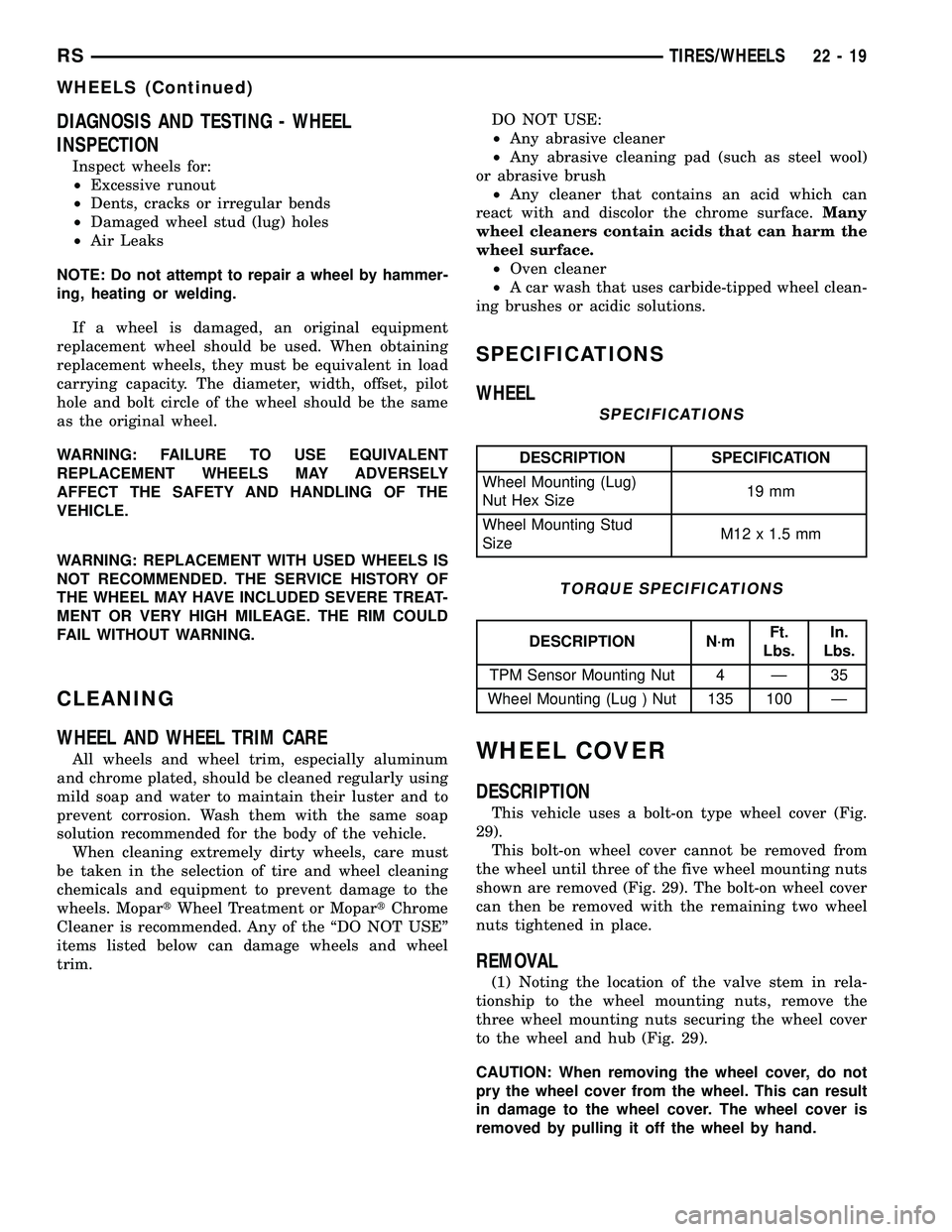
WHEEL
SPECIFICATIONS
DESCRIPTION SPECIFICATION
Wheel Mounting (Lug)
Nut Hex Size19 mm
Wheel Mounting Stud
SizeM12 x 1.5 mm
TORQUE SPECIFICATIONS
DESCRIPTION N´mFt.
Lbs.In.
Lbs.
TPM Sensor Mounting Nut 4 Ð 35
Wheel Mounting (Lug ) Nut 135 100 Ð
WHEEL COVER
DESCRIPTION
This vehicle uses a bolt-on type wheel cover (Fig.
29).
This bolt-on wheel cover cannot be removed from
the wheel until three of the five wheel mounting nuts
shown are removed (Fig. 29). The bolt-on wheel cover
can then be removed with the remaining two wheel
nuts tightened in place.
REMOVAL
(1) Noting the location of the valve stem in rela-
tionship to the wheel mounting nuts, remove the
three wheel mounting nuts securing the wheel cover
to the wheel and hub (Fig. 29).
CAUTION: When removing the wheel cover, do not
pry the wheel cover from the wheel. This can result
in damage to the wheel cover. The wheel cover is
removed by pulling it off the wheel by hand.
RSTIRES/WHEELS22-19
WHEELS (Continued)