2005 CHRYSLER CARAVAN ECU
[x] Cancel search: ECUPage 1766 of 2339
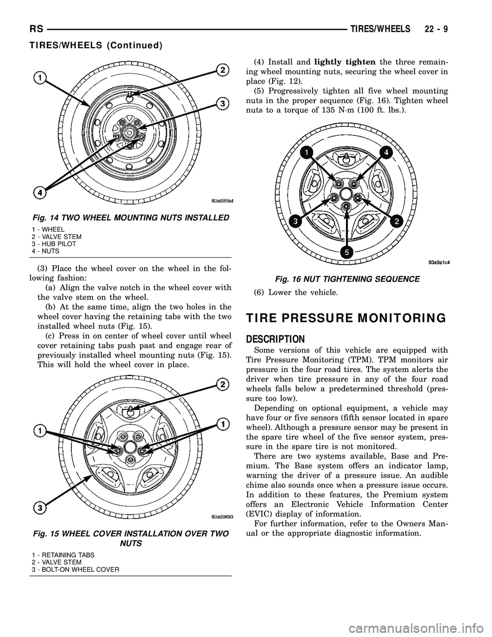
(3) Place the wheel cover on the wheel in the fol-
lowing fashion:
(a) Align the valve notch in the wheel cover with
the valve stem on the wheel.
(b) At the same time, align the two holes in the
wheel cover having the retaining tabs with the two
installed wheel nuts (Fig. 15).
(c) Press in on center of wheel cover until wheel
cover retaining tabs push past and engage rear of
previously installed wheel mounting nuts (Fig. 15).
This will hold the wheel cover in place.(4) Install andlightly tightenthe three remain-
ing wheel mounting nuts, securing the wheel cover in
place (Fig. 12).
(5) Progressively tighten all five wheel mounting
nuts in the proper sequence (Fig. 16). Tighten wheel
nuts to a torque of 135 N´m (100 ft. lbs.).
(6) Lower the vehicle.
TIRE PRESSURE MONITORING
DESCRIPTION
Some versions of this vehicle are equipped with
Tire Pressure Monitoring (TPM). TPM monitors air
pressure in the four road tires. The system alerts the
driver when tire pressure in any of the four road
wheels falls below a predetermined threshold (pres-
sure too low).
Depending on optional equipment, a vehicle may
have four or five sensors (fifth sensor located in spare
wheel). Although a pressure sensor may be present in
the spare tire wheel of the five sensor system, pres-
sure in the spare tire is not monitored.
There are two systems available, Base and Pre-
mium. The Base system offers an indicator lamp,
warning the driver of a pressure issue. An audible
chime also sounds once when a pressure issue occurs.
In addition to these features, the Premium system
offers an Electronic Vehicle Information Center
(EVIC) display of information.
For further information, refer to the Owners Man-
ual or the appropriate diagnostic information.
Fig. 14 TWO WHEEL MOUNTING NUTS INSTALLED
1 - WHEEL
2 - VALVE STEM
3 - HUB PILOT
4 - NUTS
Fig. 15 WHEEL COVER INSTALLATION OVER TWO
NUTS
1 - RETAINING TABS
2 - VALVE STEM
3 - BOLT-ON WHEEL COVER
Fig. 16 NUT TIGHTENING SEQUENCE
RSTIRES/WHEELS22-9
TIRES/WHEELS (Continued)
Page 1776 of 2339
DIAGNOSIS AND TESTING - WHEEL
INSPECTION
Inspect wheels for:
²Excessive runout
²Dents, cracks or irregular bends
²Damaged wheel stud (lug) holes
²Air Leaks
NOTE: Do not attempt to repair a wheel by hammer-
ing, heating or welding.
If a wheel is damaged, an original equipment
replacement wheel should be used. When obtaining
replacement wheels, they must be equivalent in load
carrying capacity. The diameter, width, offset, pilot
hole and bolt circle of the wheel should be the same
as the original wheel.
WARNING: FAILURE TO USE EQUIVALENT
REPLACEMENT WHEELS MAY ADVERSELY
AFFECT THE SAFETY AND HANDLING OF THE
VEHICLE.
WARNING: REPLACEMENT WITH USED WHEELS IS
NOT RECOMMENDED. THE SERVICE HISTORY OF
THE WHEEL MAY HAVE INCLUDED SEVERE TREAT-
MENT OR VERY HIGH MILEAGE. THE RIM COULD
FAIL WITHOUT WARNING.
CLEANING
WHEEL AND WHEEL TRIM CARE
All wheels and wheel trim, especially aluminum
and chrome plated, should be cleaned regularly using
mild soap and water to maintain their luster and to
prevent corrosion. Wash them with the same soap
solution recommended for the body of the vehicle.
When cleaning extremely dirty wheels, care must
be taken in the selection of tire and wheel cleaning
chemicals and equipment to prevent damage to the
wheels. MopartWheel Treatment or MopartChrome
Cleaner is recommended. Any of the ªDO NOT USEº
items listed below can damage wheels and wheel
trim.DO NOT USE:
²Any abrasive cleaner
²Any abrasive cleaning pad (such as steel wool)
or abrasive brush
²Any cleaner that contains an acid which can
react with and discolor the chrome surface.Many
wheel cleaners contain acids that can harm the
wheel surface.
²Oven cleaner
²A car wash that uses carbide-tipped wheel clean-
ing brushes or acidic solutions.
SPECIFICATIONS
WHEEL
SPECIFICATIONS
DESCRIPTION SPECIFICATION
Wheel Mounting (Lug)
Nut Hex Size19 mm
Wheel Mounting Stud
SizeM12 x 1.5 mm
TORQUE SPECIFICATIONS
DESCRIPTION N´mFt.
Lbs.In.
Lbs.
TPM Sensor Mounting Nut 4 Ð 35
Wheel Mounting (Lug ) Nut 135 100 Ð
WHEEL COVER
DESCRIPTION
This vehicle uses a bolt-on type wheel cover (Fig.
29).
This bolt-on wheel cover cannot be removed from
the wheel until three of the five wheel mounting nuts
shown are removed (Fig. 29). The bolt-on wheel cover
can then be removed with the remaining two wheel
nuts tightened in place.
REMOVAL
(1) Noting the location of the valve stem in rela-
tionship to the wheel mounting nuts, remove the
three wheel mounting nuts securing the wheel cover
to the wheel and hub (Fig. 29).
CAUTION: When removing the wheel cover, do not
pry the wheel cover from the wheel. This can result
in damage to the wheel cover. The wheel cover is
removed by pulling it off the wheel by hand.
RSTIRES/WHEELS22-19
WHEELS (Continued)
Page 1777 of 2339
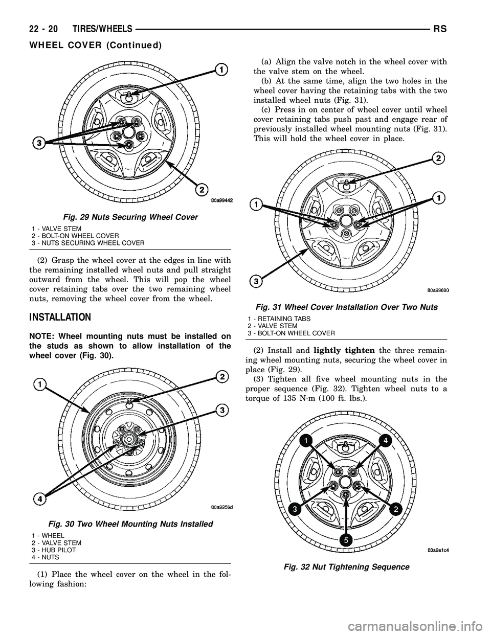
(2) Grasp the wheel cover at the edges in line with
the remaining installed wheel nuts and pull straight
outward from the wheel. This will pop the wheel
cover retaining tabs over the two remaining wheel
nuts, removing the wheel cover from the wheel.
INSTALLATION
NOTE: Wheel mounting nuts must be installed on
the studs as shown to allow installation of the
wheel cover (Fig. 30).
(1) Place the wheel cover on the wheel in the fol-
lowing fashion:(a) Align the valve notch in the wheel cover with
the valve stem on the wheel.
(b) At the same time, align the two holes in the
wheel cover having the retaining tabs with the two
installed wheel nuts (Fig. 31).
(c) Press in on center of wheel cover until wheel
cover retaining tabs push past and engage rear of
previously installed wheel mounting nuts (Fig. 31).
This will hold the wheel cover in place.
(2) Install andlightly tightenthe three remain-
ing wheel mounting nuts, securing the wheel cover in
place (Fig. 29).
(3) Tighten all five wheel mounting nuts in the
proper sequence (Fig. 32). Tighten wheel nuts to a
torque of 135 N´m (100 ft. lbs.).
Fig. 29 Nuts Securing Wheel Cover
1 - VALVE STEM
2 - BOLT-ON WHEEL COVER
3 - NUTS SECURING WHEEL COVER
Fig. 30 Two Wheel Mounting Nuts Installed
1 - WHEEL
2 - VALVE STEM
3 - HUB PILOT
4 - NUTS
Fig. 31 Wheel Cover Installation Over Two Nuts
1 - RETAINING TABS
2 - VALVE STEM
3 - BOLT-ON WHEEL COVER
Fig. 32 Nut Tightening Sequence
22 - 20 TIRES/WHEELSRS
WHEEL COVER (Continued)
Page 1778 of 2339
WHEEL MOUNTING STUDS -
FRONT
REMOVAL
NOTE: Before proceeding, (Refer to 5 - BRAKES -
WARNING)(Refer to 5 - BRAKES - CAUTION).
CAUTION: Wheel mounting studs MUST NOT be
hammered out of hub flange of hub and bearing
assembly. If a stud is removed by hammering it out,
damage to hub and bearing assembly will occur
leading to premature bearing failure.
(1) Raise vehicle. (Refer to LUBRICATION &
MAINTENANCE/HOISTING - STANDARD PROCE-
DURE)
(2) Remove front wheel and tire assembly. (Refer
to 22 - TIRES/WHEELS - REMOVAL)
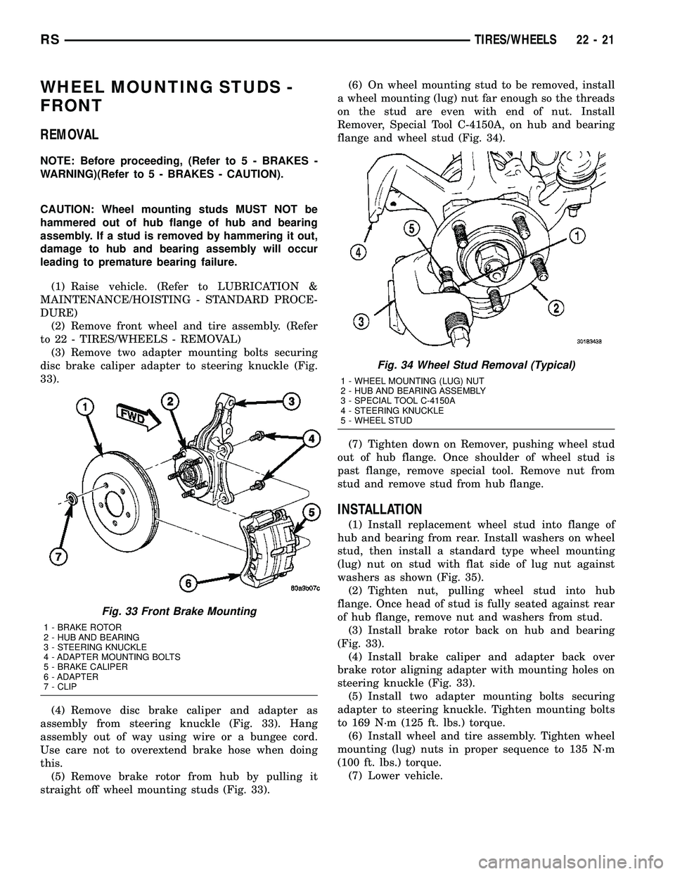
(3) Remove two adapter mounting bolts securing
disc brake caliper adapter to steering knuckle (Fig.
33).
(4) Remove disc brake caliper and adapter as
assembly from steering knuckle (Fig. 33). Hang
assembly out of way using wire or a bungee cord.
Use care not to overextend brake hose when doing
this.
(5) Remove brake rotor from hub by pulling it
straight off wheel mounting studs (Fig. 33).(6) On wheel mounting stud to be removed, install
a wheel mounting (lug) nut far enough so the threads
on the stud are even with end of nut. Install
Remover, Special Tool C-4150A, on hub and bearing
flange and wheel stud (Fig. 34).
(7) Tighten down on Remover, pushing wheel stud
out of hub flange. Once shoulder of wheel stud is
past flange, remove special tool. Remove nut from
stud and remove stud from hub flange.
INSTALLATION
(1) Install replacement wheel stud into flange of
hub and bearing from rear. Install washers on wheel
stud, then install a standard type wheel mounting
(lug) nut on stud with flat side of lug nut against
washers as shown (Fig. 35).
(2) Tighten nut, pulling wheel stud into hub
flange. Once head of stud is fully seated against rear
of hub flange, remove nut and washers from stud.
(3) Install brake rotor back on hub and bearing
(Fig. 33).
(4) Install brake caliper and adapter back over
brake rotor aligning adapter with mounting holes on
steering knuckle (Fig. 33).
(5) Install two adapter mounting bolts securing
adapter to steering knuckle. Tighten mounting bolts
to 169 N´m (125 ft. lbs.) torque.
(6) Install wheel and tire assembly. Tighten wheel
mounting (lug) nuts in proper sequence to 135 N´m
(100 ft. lbs.) torque.
(7) Lower vehicle.
Fig. 33 Front Brake Mounting
1 - BRAKE ROTOR
2 - HUB AND BEARING
3 - STEERING KNUCKLE
4 - ADAPTER MOUNTING BOLTS
5 - BRAKE CALIPER
6 - ADAPTER
7 - CLIP
Fig. 34 Wheel Stud Removal (Typical)
1 - WHEEL MOUNTING (LUG) NUT
2 - HUB AND BEARING ASSEMBLY
3 - SPECIAL TOOL C-4150A
4 - STEERING KNUCKLE
5 - WHEEL STUD
RSTIRES/WHEELS22-21
Page 1787 of 2339
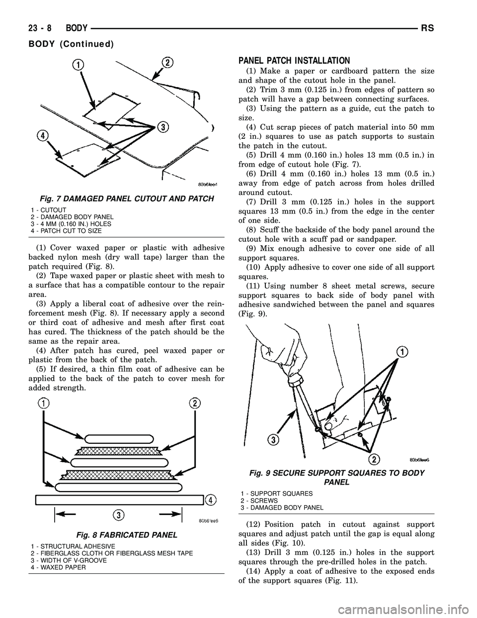
(1) Cover waxed paper or plastic with adhesive
backed nylon mesh (dry wall tape) larger than the
patch required (Fig. 8).
(2) Tape waxed paper or plastic sheet with mesh to
a surface that has a compatible contour to the repair
area.
(3) Apply a liberal coat of adhesive over the rein-
forcement mesh (Fig. 8). If necessary apply a second
or third coat of adhesive and mesh after first coat
has cured. The thickness of the patch should be the
same as the repair area.
(4) After patch has cured, peel waxed paper or
plastic from the back of the patch.
(5) If desired, a thin film coat of adhesive can be
applied to the back of the patch to cover mesh for
added strength.
PANEL PATCH INSTALLATION
(1) Make a paper or cardboard pattern the size
and shape of the cutout hole in the panel.
(2) Trim 3 mm (0.125 in.) from edges of pattern so
patch will have a gap between connecting surfaces.
(3) Using the pattern as a guide, cut the patch to
size.
(4) Cut scrap pieces of patch material into 50 mm
(2 in.) squares to use as patch supports to sustain
the patch in the cutout.
(5) Drill 4 mm (0.160 in.) holes 13 mm (0.5 in.) in
from edge of cutout hole (Fig. 7).
(6) Drill 4 mm (0.160 in.) holes 13 mm (0.5 in.)
away from edge of patch across from holes drilled
around cutout.
(7) Drill 3 mm (0.125 in.) holes in the support
squares 13 mm (0.5 in.) from the edge in the center
of one side.
(8) Scuff the backside of the body panel around the
cutout hole with a scuff pad or sandpaper.
(9) Mix enough adhesive to cover one side of all
support squares.
(10) Apply adhesive to cover one side of all support
squares.
(11) Using number 8 sheet metal screws, secure
support squares to back side of body panel with
adhesive sandwiched between the panel and squares
(Fig. 9).
(12) Position patch in cutout against support
squares and adjust patch until the gap is equal along
all sides (Fig. 10).
(13) Drill 3 mm (0.125 in.) holes in the support
squares through the pre-drilled holes in the patch.
(14) Apply a coat of adhesive to the exposed ends
of the support squares (Fig. 11).
Fig. 7 DAMAGED PANEL CUTOUT AND PATCH
1 - CUTOUT
2 - DAMAGED BODY PANEL
3-4MM(0.160 IN.) HOLES
4 - PATCH CUT TO SIZE
Fig. 8 FABRICATED PANEL
1 - STRUCTURAL ADHESIVE
2 - FIBERGLASS CLOTH OR FIBERGLASS MESH TAPE
3 - WIDTH OF V-GROOVE
4 - WAXED PAPER
Fig. 9 SECURE SUPPORT SQUARES TO BODY
PANEL
1 - SUPPORT SQUARES
2 - SCREWS
3 - DAMAGED BODY PANEL
23 - 8 BODYRS
BODY (Continued)
Page 1789 of 2339
(a) If the heat staked or component seam loca-
tion is loose, hold the two components tightly
together and using a soldering gun with a flat tip,
melt the material securing the components
together. Do not over heat the affected area, dam-
age to the exterior of the trim panel may occur.
(b) If the heat staked material is broken or miss-
ing, use a hot glue gun to apply new material to
the area to be repaired. The panels that are being
heat staked must be held together while the apply-ing the glue. Once the new material is in place, it
may be necessary to use a soldering gun to melt
the newly applied material. Do not over heat the
affected area, damage to the exterior of the trim
panel may occur.
(4) Allow the repaired area to cool and verify the
repair.
(5) Install trim panel.
SPECIFICATIONS
TORQUE
TORQUE SPECIFICATIONS
DESCRIPTION N´m Ft. Lbs. In. Lbs.
All seat belt anchor bolts 39 29 Ð
Armrest shoulder bolt 29 21 Ð
Bench seat riser bolts 48 35 Ð
Bench seat track nuts 48 35 Ð
Quad bucket seat track to cushion frame bolts 40 30 Ð
Bucket seat back pivot bolts 33 24 Ð
Center seat to seat track bolts 24 17 Ð
Child seat module screws (bench seats) 7 Ð 62
Child seat module screws (quad seats) 13.5 10 Ð
Crossmember to radiator closure panel bolts 28 21 Ð
Door check strap to door end frame 12 Ð 105
Door latch to door end frame bolts 10 Ð 89
Floor latch to seat cushion frame bolts 27 19 Ð
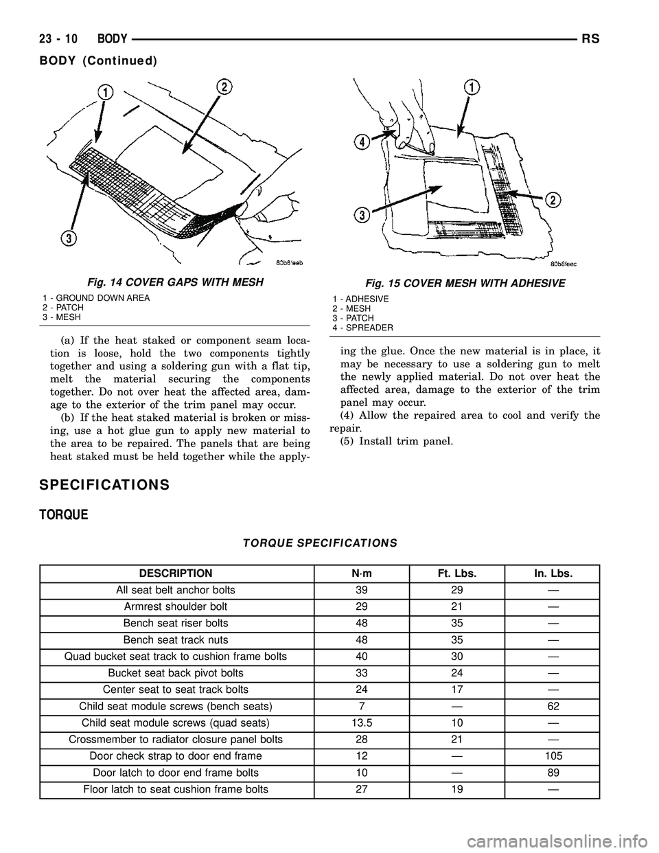
Fig. 14 COVER GAPS WITH MESH
1 - GROUND DOWN AREA
2 - PATCH
3 - MESH
Fig. 15 COVER MESH WITH ADHESIVE
1 - ADHESIVE
2 - MESH
3 - PATCH
4 - SPREADER
23 - 10 BODYRS
BODY (Continued)
Page 1798 of 2339
(10) Verify door latch and power door lock opera-
tion.
(11) Install watershield and front door trim panel.
LATCH STRIKER
REMOVAL
(1) Mark outline of door striker on B-pillar to aid
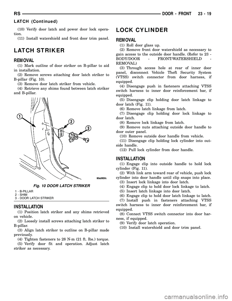
in installation.
(2) Remove screws attaching door latch striker to
B-pillar (Fig. 10).
(3) Remove door latch striker from vehicle.
(4) Retrieve any shims found between latch striker
and B-pillar.
INSTALLATION
(1) Position latch striker and any shims retrieved
on vehicle.
(2) Loosely install screws attaching latch striker to
B-pillar.
(3) Align latch striker to outline on B-pillar made
previously.
(4) Tighten fasteners to 28 N´m (21 ft. lbs.) torque.
(5) Verify door fit and operation. Adjust latch
striker as necessary.
LOCK CYLINDER
REMOVAL
(1) Roll door glass up.
(2) Remove front door watershield as necessary to
gain access to the outside door handle. (Refer to 23 -
BODY/DOOR - FRONT/WATERSHIELD -
REMOVAL)
(3) Through access hole at rear of inner door
panel, disconnect Vehicle Theft Security System
(VTSS) switch connector from door harness, if
equipped.
(4) Disengage push in fasteners attaching VTSS
switch harness to inner door reinforcement bar, if
equipped.
(5) Disengage clip holding door latch linkage to
door latch (Fig. 11).
(6) Remove latch linkage from latch.
(7) Disengage clip holding door lock linkage to
door latch.
(8) Remove lock linkage from latch.
(9) Remove nuts attaching outside door handle to
door outer panel.
(10) Remove outside door handle from vehicle.
(11) Disengage clip holding lock cylinder into out-
side handle.
(12) Pull lock cylinder from door handle.
INSTALLATION
(1) Engage clip into outside handle to hold lock
cylinder (Fig. 11).
(2) With link arm toward rear of vehicle, push lock
cylinder into door handle until clip snaps into place.
(3) Insert lock linkage into door latch.
(4) Engage clip to hold door lock linkage to latch.
(5) Insert latch linkage into door latch.
(6) Engage clip to hold door latch linkage to latch.
(7) Install push in fasteners attaching VTSS
switch harness to inner door reinforcement bar, if
equipped.
(8) Connect VTSS switch connector into door har-
ness, if equipped.
(9) Verify door latch operation.
(10) Install watershield and door trim panel.
Fig. 10 DOOR LATCH STRIKER
1 - B-PILLAR
2 - SHIM
3 - DOOR LATCH STRIKER
RSDOOR - FRONT23-19
LATCH (Continued)
Page 1800 of 2339
(4) Place front door trim panel in position on door.
(5) Install trim panel into inner belt molding at
top of door.
(6) Install clips to attach door trim to door frame
around perimeter of panel.
(7) If equipped, install screw to attach door trim to
door panel behind inside latch release handle.
(8) If equipped, connect power switch into wire
connector.
(9) Place power accessary switch in position on
door trim.
(10) Connect wire connector into memory seat/mir-
ror switch and install switch into trim panel.
(11) Install screws to attach accessary switch
panel to door trim.
(12) Install screw cover into switch panel.
(13) If equipped, install window crank.
(14) If equipped, install screws to attach trim
panel to door inside map pocket.
(15) If equipped, install screw to attach door pull
cup to inner door panel.
(16) If equipped, install screws to attach door
assist handle to inner door panel.
(17) Connect wire connector into courtesy lamp.
(18) Install lamp in door trim.
(19) Install switch bezel.
WATERSHIELD
REMOVAL
(1) Remove door trim panel. (Refer to 23 - BODY/
DOOR - FRONT/TRIM PANEL - REMOVAL)
(2) Remove the front door speaker. (Refer to 8 -
ELECTRICAL/AUDIO/SPEAKER - REMOVAL)
(3) Peel watershield away from adhesive around
perimeter of inner door panel.
INSTALLATION
(1) Insure that enough adhesive remains to
securely retain the water dam. Replace as necessary.
(2) Place the shield into position and press
securely to adhesive making sure to properly route
wiring and linkages.
(3) Install the front door speaker. (Refer to 8 -
ELECTRICAL/AUDIO/SPEAKER - INSTALLATION)
(4) Install door trim panel. (Refer to 23 - BODY/
DOOR - FRONT/TRIM PANEL - INSTALLATION)
WINDOW CRANK
REMOVAL
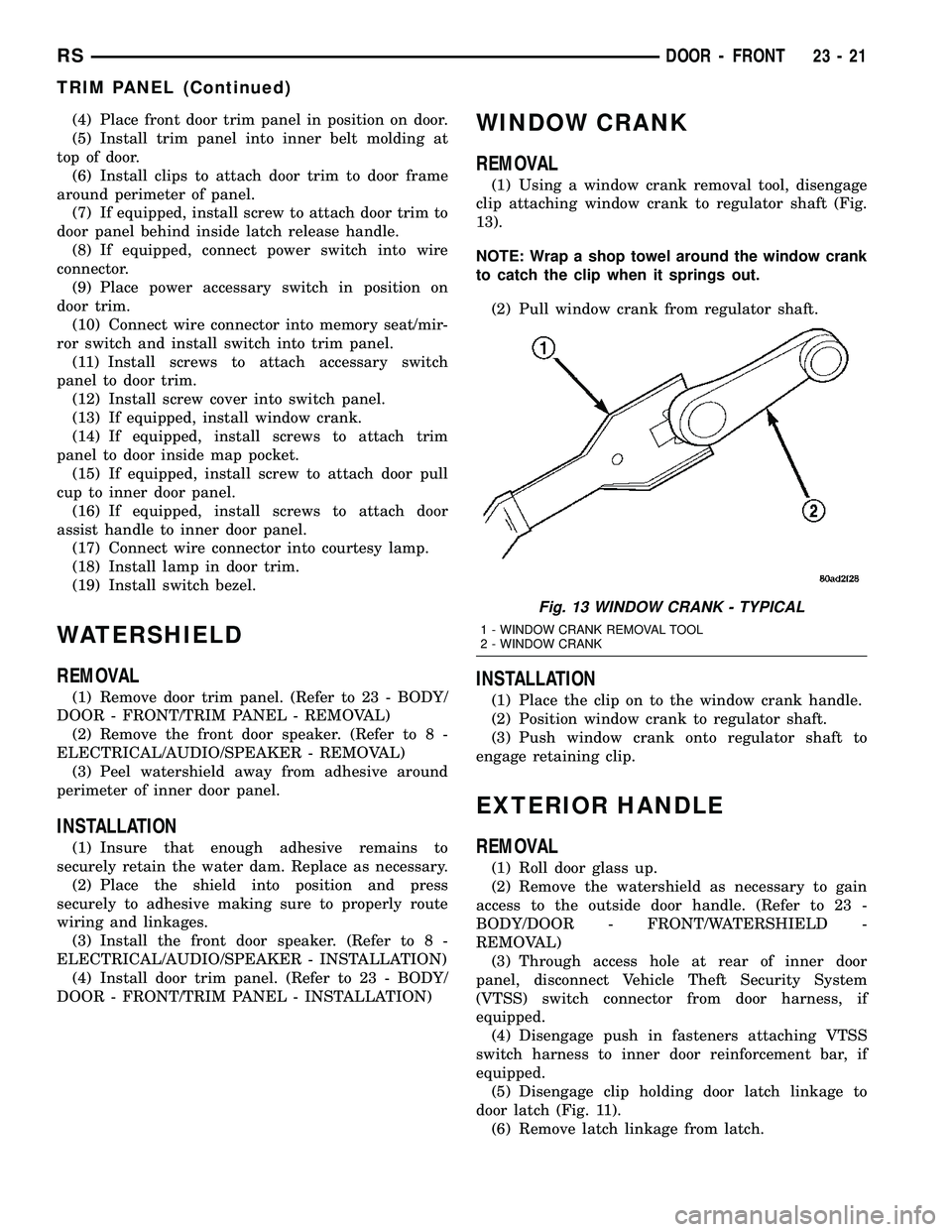
(1) Using a window crank removal tool, disengage
clip attaching window crank to regulator shaft (Fig.
13).
NOTE: Wrap a shop towel around the window crank
to catch the clip when it springs out.
(2) Pull window crank from regulator shaft.
INSTALLATION
(1) Place the clip on to the window crank handle.
(2) Position window crank to regulator shaft.
(3) Push window crank onto regulator shaft to
engage retaining clip.
EXTERIOR HANDLE
REMOVAL
(1) Roll door glass up.
(2) Remove the watershield as necessary to gain
access to the outside door handle. (Refer to 23 -
BODY/DOOR - FRONT/WATERSHIELD -
REMOVAL)
(3) Through access hole at rear of inner door
panel, disconnect Vehicle Theft Security System
(VTSS) switch connector from door harness, if
equipped.
(4) Disengage push in fasteners attaching VTSS
switch harness to inner door reinforcement bar, if
equipped.
(5) Disengage clip holding door latch linkage to
door latch (Fig. 11).
(6) Remove latch linkage from latch.
Fig. 13 WINDOW CRANK - TYPICAL
1 - WINDOW CRANK REMOVAL TOOL
2 - WINDOW CRANK
RSDOOR - FRONT23-21
TRIM PANEL (Continued)