2005 CHRYSLER CARAVAN wheel torque
[x] Cancel search: wheel torquePage 1795 of 2339
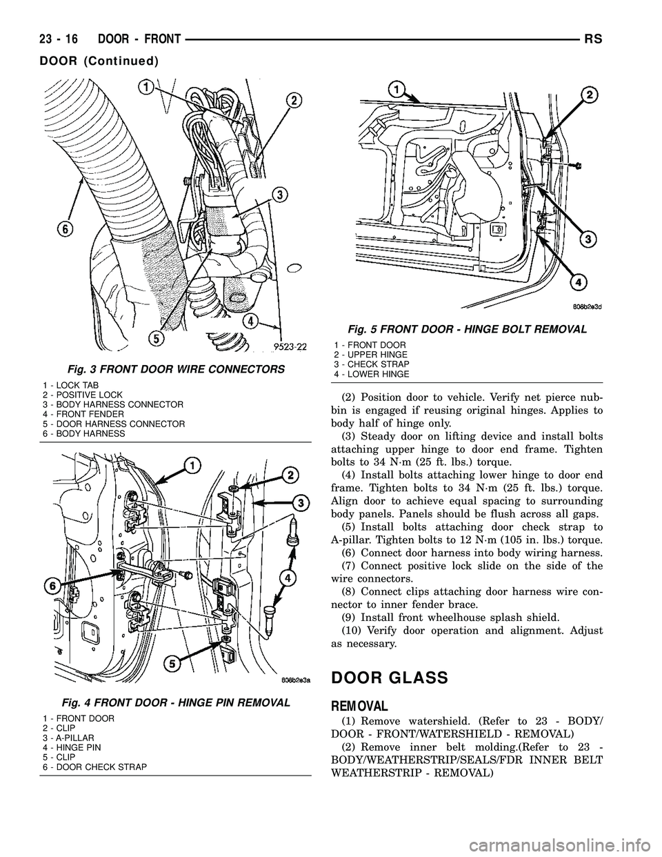
(2) Position door to vehicle. Verify net pierce nub-
bin is engaged if reusing original hinges. Applies to
body half of hinge only.
(3) Steady door on lifting device and install bolts
attaching upper hinge to door end frame. Tighten
bolts to 34 N´m (25 ft. lbs.) torque.
(4) Install bolts attaching lower hinge to door end
frame. Tighten bolts to 34 N´m (25 ft. lbs.) torque.
Align door to achieve equal spacing to surrounding
body panels. Panels should be flush across all gaps.
(5) Install bolts attaching door check strap to
A-pillar. Tighten bolts to 12 N´m (105 in. lbs.) torque.
(6) Connect door harness into body wiring harness.
(7) Connect positive lock slide on the side of the
wire connectors.
(8) Connect clips attaching door harness wire con-
nector to inner fender brace.
(9) Install front wheelhouse splash shield.
(10) Verify door operation and alignment. Adjust
as necessary.
DOOR GLASS
REMOVAL
(1) Remove watershield. (Refer to 23 - BODY/
DOOR - FRONT/WATERSHIELD - REMOVAL)
(2) Remove inner belt molding.(Refer to 23 -
BODY/WEATHERSTRIP/SEALS/FDR INNER BELT
WEATHERSTRIP - REMOVAL)
Fig. 3 FRONT DOOR WIRE CONNECTORS
1 - LOCK TAB
2 - POSITIVE LOCK
3 - BODY HARNESS CONNECTOR
4 - FRONT FENDER
5 - DOOR HARNESS CONNECTOR
6 - BODY HARNESS
Fig. 4 FRONT DOOR - HINGE PIN REMOVAL
1 - FRONT DOOR
2 - CLIP
3 - A-PILLAR
4 - HINGE PIN
5 - CLIP
6 - DOOR CHECK STRAP
Fig. 5 FRONT DOOR - HINGE BOLT REMOVAL
1 - FRONT DOOR
2 - UPPER HINGE
3 - CHECK STRAP
4 - LOWER HINGE
23 - 16 DOOR - FRONTRS
DOOR (Continued)
Page 1836 of 2339
(2) Insert ends of crossmember between layered
metal sections of radiator closure panel at each side
of radiator.
(3) Align with paint breaks around bolt heads.
(4) Install bolts attaching ends of crossmember to
radiator closure panel (Fig. 16). Tighten bolts to 19
N´m (14 ft. lbs.) torque.
(5) Install bolts attaching radiator isolators to
crossmember.
(6) Install screw attaching coolant recovery bottle
to crossmember.
(7) Install bolt attaching air cleaner housing to
crossmember.
(8) Install engine air inlet resonator.
(9) Install hood prop rod.
(10) Align hood latch by placing latch over net
pierce tabs. If alignment is required, flatten tabs.
(11) Install bolts attaching hood latch to cross-
member and clip cable. Tighten bolts to 13.5 N´m (10
ft. lbs.) torque.
(12) Install radiator sight shield.
(13) Verify hood latch operation and hood align-
ment.
FRONT WHEELHOUSE
SPLASH SHIELD
REMOVAL
(1) Hoist and support vehicle on safety stands.
(Refer to LUBRICATION & MAINTENANCE/HOIST-
ING - STANDARD PROCEDURE).
(2) Remove front wheel.
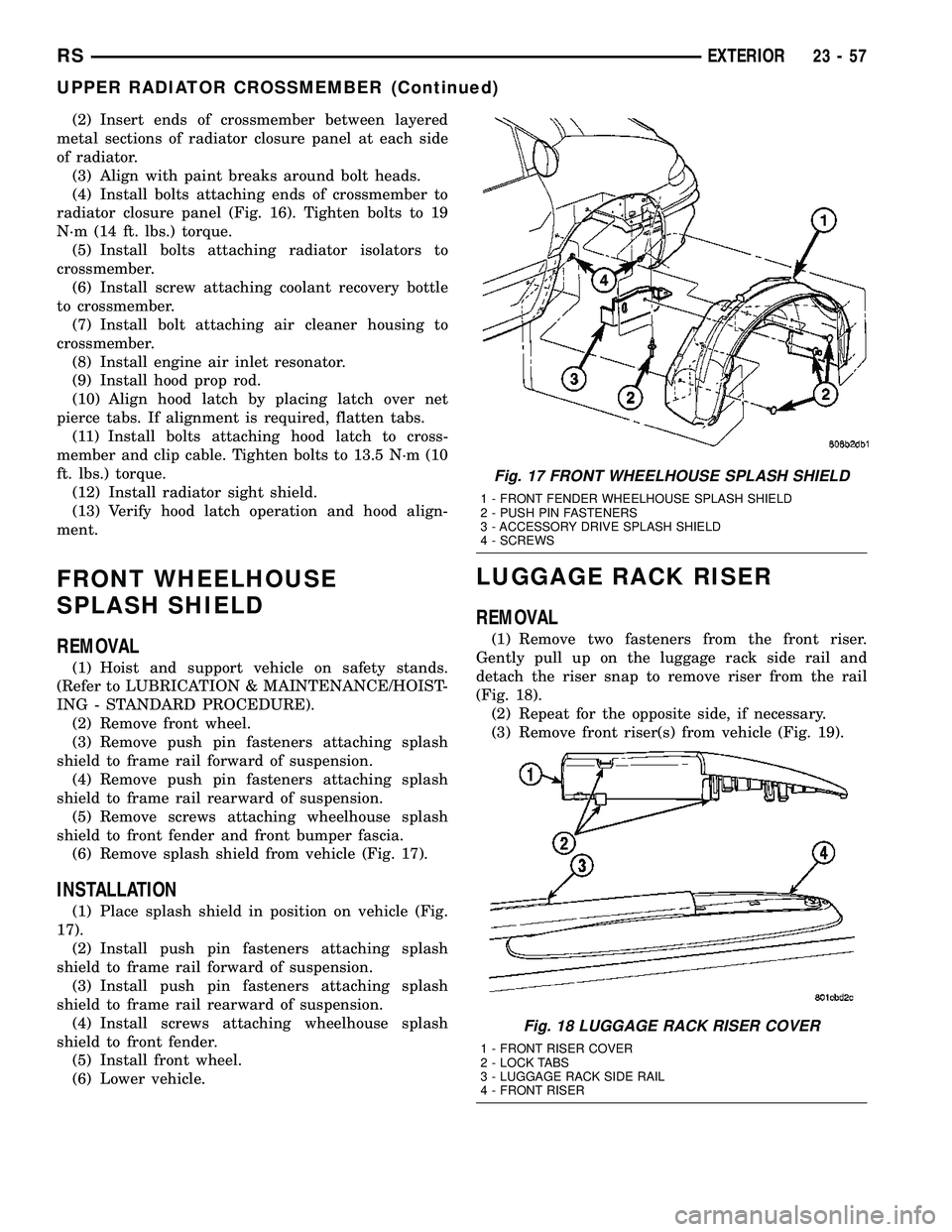
(3) Remove push pin fasteners attaching splash
shield to frame rail forward of suspension.
(4) Remove push pin fasteners attaching splash
shield to frame rail rearward of suspension.
(5) Remove screws attaching wheelhouse splash
shield to front fender and front bumper fascia.
(6) Remove splash shield from vehicle (Fig. 17).
INSTALLATION
(1) Place splash shield in position on vehicle (Fig.
17).
(2) Install push pin fasteners attaching splash
shield to frame rail forward of suspension.
(3) Install push pin fasteners attaching splash
shield to frame rail rearward of suspension.
(4) Install screws attaching wheelhouse splash
shield to front fender.
(5) Install front wheel.
(6) Lower vehicle.
LUGGAGE RACK RISER
REMOVAL
(1) Remove two fasteners from the front riser.
Gently pull up on the luggage rack side rail and
detach the riser snap to remove riser from the rail
(Fig. 18).
(2) Repeat for the opposite side, if necessary.
(3) Remove front riser(s) from vehicle (Fig. 19).
Fig. 17 FRONT WHEELHOUSE SPLASH SHIELD
1 - FRONT FENDER WHEELHOUSE SPLASH SHIELD
2 - PUSH PIN FASTENERS
3 - ACCESSORY DRIVE SPLASH SHIELD
4 - SCREWS
Fig. 18 LUGGAGE RACK RISER COVER
1 - FRONT RISER COVER
2 - LOCK TABS
3 - LUGGAGE RACK SIDE RAIL
4 - FRONT RISER
RSEXTERIOR23-57
UPPER RADIATOR CROSSMEMBER (Continued)
Page 1838 of 2339
INSTALLATION
NOTE: The crossbar assemblies are designed to be
installed in only one way. Check top and bottom
surfaces of the crossbar for the word FRONT and
directional arrows. The directional arrows must
point toward the front of the vehicle.
(1) Place crossbar in position on vehicle.
(2) Work from side to side sliding the crossbar
assembly back a little at a time to ensure it remains
perpendicular to the side rails.
(3) Position first crossbar assembly crossbar at the
second most rearward locator holes. Press the top of
the stanchion lever to lock it into position.
(4) Position the second crossbar assembly in the
second hole from the front. Lock into place.
(5) Place luggage rack riser into position.
(6) Install two fasteners into riser. Tighten fasten-
ers to 4 mm (35 in. lbs.) torque.
REAR QUARTER PANEL/
FENDER AIR EXHAUSTER
DESCRIPTION
Air exhausters, designed to conform to the body
structure, allow air entering at the front of the vehi-
cle to flow out the back. By reducing air pressure
within the vehicle, the exhausters also reduce blower
noise at any given air flow level compared to operat-
ing without them and help reduce door closing effort.
They are located in the lower rear comers of the
body.
REMOVAL
SHORT WHEELBASE
(1) Remove the rear fascia from the body. (Refer to
13 - FRAMES & BUMPERS/BUMPERS/REAR FAS-
CIA - REMOVAL).
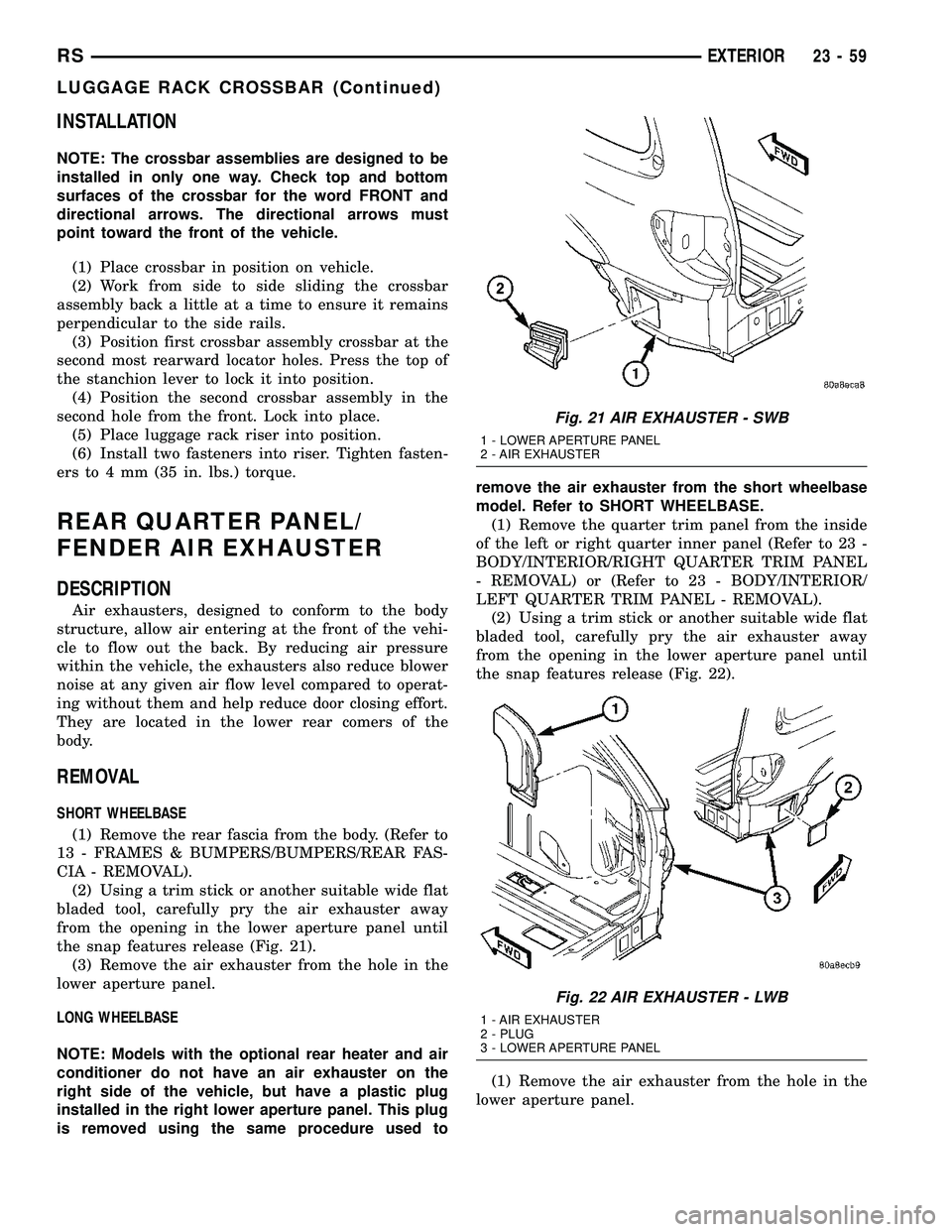
(2) Using a trim stick or another suitable wide flat
bladed tool, carefully pry the air exhauster away
from the opening in the lower aperture panel until
the snap features release (Fig. 21).
(3) Remove the air exhauster from the hole in the
lower aperture panel.
LONG WHEELBASE
NOTE: Models with the optional rear heater and air
conditioner do not have an air exhauster on the
right side of the vehicle, but have a plastic plug
installed in the right lower aperture panel. This plug
is removed using the same procedure used toremove the air exhauster from the short wheelbase
model. Refer to SHORT WHEELBASE.
(1) Remove the quarter trim panel from the inside
of the left or right quarter inner panel (Refer to 23 -
BODY/INTERIOR/RIGHT QUARTER TRIM PANEL
- REMOVAL) or (Refer to 23 - BODY/INTERIOR/
LEFT QUARTER TRIM PANEL - REMOVAL).
(2) Using a trim stick or another suitable wide flat
bladed tool, carefully pry the air exhauster away
from the opening in the lower aperture panel until
the snap features release (Fig. 22).
(1) Remove the air exhauster from the hole in the
lower aperture panel.
Fig. 21 AIR EXHAUSTER - SWB
1 - LOWER APERTURE PANEL
2 - AIR EXHAUSTER
Fig. 22 AIR EXHAUSTER - LWB
1 - AIR EXHAUSTER
2 - PLUG
3 - LOWER APERTURE PANEL
RSEXTERIOR23-59
LUGGAGE RACK CROSSBAR (Continued)
Page 1873 of 2339
LEFT D-PILLAR TRIM PANEL
REMOVAL
(1) Remove rear header trim cover.
(2) Remove liftgate sill plate.
(3) Remove second row seat belt turning loop on
long wheel base vehicle.
(4) Remove bolt attaching second row seat belt
lower anchor to quarter on short wheel base vehicle.
(5) Disengage hidden clips attaching trim to D-pil-
lar.
(6) Disconnect speaker wire connector, if equipped.
(7) Pass seat belt through slot in D-pillar trim
panel on short wheel base vehicle.
(8) Remove D-pillar trim from vehicle.
INSTALLATION
(1) Pass seat belt through slot in D-pillar trim
panel on short wheel base vehicle.
(2) Position D-pillar trim panel on vehicle.
(3) Connect speaker wire connector to speaker, if
equipped.
(4) Align locating pins on backside of trim panel to
mating holes in inner quarter panel.
(5) Engage hidden clips attaching trim to D-pillar.
(6) Install bolt attaching second row seat belt
lower anchor to quarter on short wheel base vehicle.
Tighten all seat belt bolts to 39 N´m (29 ft. lbs.).
(7) Install second row seat belt turning loop on
long wheel base vehicle.
(8) Install liftgate sill plate.
(9) Install rear header trim cover.
LEFT QUARTER TRIM PANEL
REMOVAL
CAUTION: Disconnect the negative cable clamp
from battery post. Damage to accessory feed circuit
can result.
(1) Remove first row seat.
(2) Remove second row seat, if equipped.
(3) Remove front door sill plate on three door vehi-
cle.
(4) Remove sliding door sill plate on four door
vehicle.
(5) Remove left quarter trim bolster.
(6) Remove C-pillar trim panel.
(7) Remove left D-pillar trim panel.
(8) Remove first row seat belt anchor.
(9) Remove second row seat belt anchor on long
wheel base vehicle.
(10) Remove screws attaching quarter trim to
quarter panel from bolster area.(11) Remove screws attaching rear edge of quarter
trim to attaching bracket or inner quarter trim
panel.
(12) Disconnect wire connector from accessory
power outlet, if equipped.
(13) Remove quarter trim from quarter panel.
(14) Pass front seat belt and turning loop through
slot in quarter trim panel on three door vehicle.
(15) Pass first row seat belt through slot in quar-
ter trim panel.
(16) Pass second row seat belt, if equipped,
through slot in quarter trim panel on long wheel
base vehicle.
(17) Remove quarter trim panel from vehicle.
INSTALLATION
(1) Position quarter trim panel on vehicle.
(2) Pass second row seat belt, if equipped, through
slot in quarter trim panel on long wheel base vehicle.
(3) Pass first row seat belt through slot in quarter
trim panel.
(4) Connect wire connector into accessory power
outlet, if equipped.
(5) Align locating pins on backside of trim panel to
mating holes in inner panels.
(6) Position quarter trim panel on inner quarter
panel.
(7) Install screws attaching rear edge of quarter
trim to attaching bracket or inner quarter panel.
(8) Install screws attaching quarter trim to inner
quarter panel in bolster area.
(9) Install second row seat belts anchor on long
wheel base vehicle. Tighten all seat belt bolts to 39
N´m (29 in. lbs.) torque.
(10) Install first row seat belt anchor.
(11) Install left D-pillar trim panel.
(12) Install C-pillar trim panel.
(13) Install upper left B-pillar trim on three door
vehicle.
(14) Install left quarter trim bolster.
(15) Install front door sill plate on three door vehi-
cle.
(16) Install sliding door sill plate on four door
vehicle.
(17) Install second row seat, if equipped.
(18) Install first row seat.
(19) Connect the battery negative cable.
LIFTGATE SILL PLATE
REMOVAL
(1) Disengage hidden clips holding sill plate to lift-
gate door opening sill (Fig. 27).
(2) Remove sill plate from vehicle.
23 - 94 INTERIORRS
Page 1876 of 2339
INSTALLATION
(1) Place bezel in position in HVAC duct opening.
(2) Push inward on bezel until clips snap in place.
Verify that all four clips have been engaged to the
bezel and that the bezel is flush to the headlining
(3) Position HVAC louver to bezel.
(4) Snap both ends of the louver into HVAC bezel.
RIGHT QUARTER TRIM PANEL
REMOVAL
CAUTION: Disconnect the battery negative cable.
Damage to accessory feed circuit can result.
(1) Remove first row seat.
(2) Remove second row seat.
(3) Remove sliding door sill trim panel.
(4) Remove quarter trim bolster.
(5) Remove D-pillar trim panel.
(6) Remove first row seat belt anchor.
(7) Remove second row seat belt anchor.
(8) Remove screws attaching quarter trim to quar-
ter panel from bolster area.
(9) Remove screws attaching rear edge of quarter
trim to attaching bracket.
(10) Disengage hidden clips attaching front of
quarter trim to quarter panel rearward of sliding
door opening and at locators.
(11) Remove quarter trim from quarter panel.
(12) Disconnect speaker wire connector on LWB
quarter trim panel with rear air conditioning.
(13) Pass second row seat belt through slot in trim
panel on long wheel base vehicle.
(14) Pass first row seat belt through slot in trim
panel.
(15) Remove quarter trim panel from vehicle.
INSTALLATION
(1) Position quarter trim panel on vehicle.
(2) Pass first row seat belt through slot in trim
panel.
(3) Pass second row seat belt through access hole
in trim panel on long wheel base vehicle.
(4) Connect wire connector into speaker on LWB
with rear air conditioning.
(5) Align locating pins on backside of trim panel to
mating holes in inner quarter panel.
(6) Engage hidden clips attaching front of quarter
trim to quarter panel rearward of sliding door open-
ing and at locators.
(7) Install screws attaching rear edge of quarter
trim to attaching bracket.
(8) Install screws attaching quarter trim to inner
quarter panel in bolster area.(9) Install second row seat belt anchor on long
wheel base vehicle. Tighten all seat belt bolts to 39
N´m (29 ft. lbs.) torque.
(10) Install first row seat belt anchor.
(11) Install D-pillar trim panel.
(12) Install C-pillar trim panel.
(13) Install quarter trim bolster.
(14) Install sliding door sill trim panel.
(15) Install second row seat, if equipped.
(16) Install first row seat.
(17) Connect the battery negative cable.
REAR VIEW MIRROR
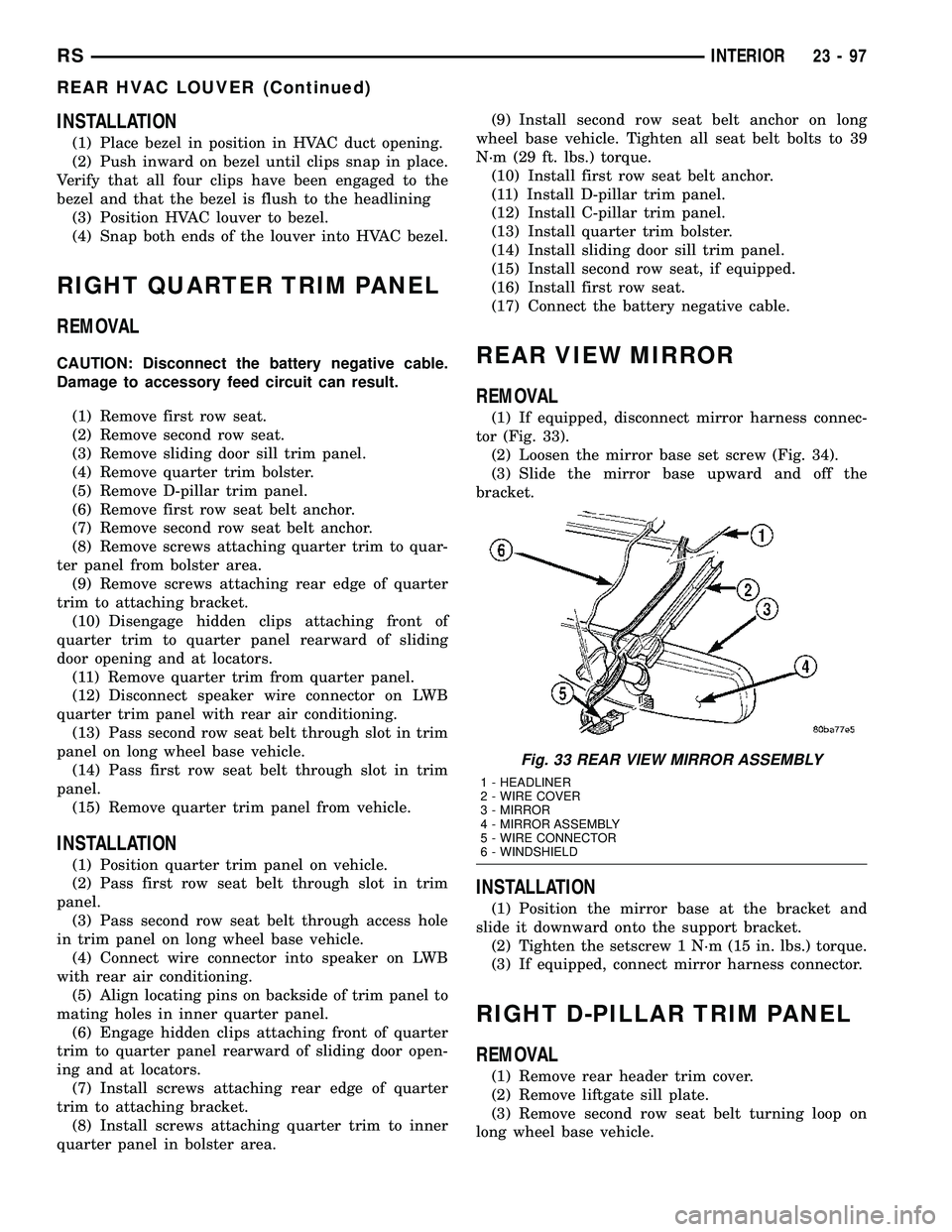
REMOVAL
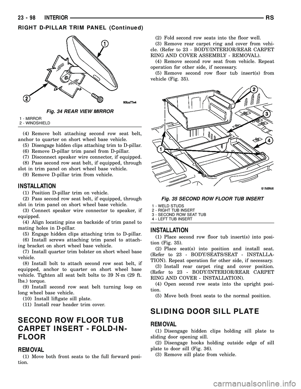
(1) If equipped, disconnect mirror harness connec-
tor (Fig. 33).
(2) Loosen the mirror base set screw (Fig. 34).
(3) Slide the mirror base upward and off the
bracket.
INSTALLATION
(1) Position the mirror base at the bracket and
slide it downward onto the support bracket.
(2) Tighten the setscrew 1 N´m (15 in. lbs.) torque.
(3) If equipped, connect mirror harness connector.
RIGHT D-PILLAR TRIM PANEL
REMOVAL
(1) Remove rear header trim cover.
(2) Remove liftgate sill plate.
(3) Remove second row seat belt turning loop on
long wheel base vehicle.
Fig. 33 REAR VIEW MIRROR ASSEMBLY
1 - HEADLINER
2 - WIRE COVER
3 - MIRROR
4 - MIRROR ASSEMBLY
5 - WIRE CONNECTOR
6 - WINDSHIELD
RSINTERIOR23-97
REAR HVAC LOUVER (Continued)
Page 1877 of 2339
(4) Remove bolt attaching second row seat belt,
anchor to quarter on short wheel base vehicle.
(5)
Disengage hidden clips attaching trim to D-pillar.
(6) Remove D-pillar trim panel from D-pillar.
(7) Disconnect speaker wire connector, if equipped.
(8) Pass second row seat belt, if equipped, through
slot in trim panel on short wheel base vehicle.
(9) Remove D-pillar trim from vehicle.
INSTALLATION
(1) Position D-pillar trim on vehicle.
(2) Pass second row seat belt, if equipped, through
slot in trim panel on short wheel base vehicle.
(3) Connect speaker wire connector to speaker, if
equipped.
(4) Align locating pins on backside of trim panel to
mating holes in D-pillar.
(5) Engage hidden clips attaching trim to D-pillar.
(6) Install screws attaching trim panel to attach-
ing bracket on short wheel base vehicle.
(7) Install quarter trim bolster on short wheel base
vehicle.
(8) Install bolt to attach second row seat belt, if
equipped, anchor to quarter on short wheel base
vehicle. Tighten all seat belt bolts to 39 N´m (29 ft.
lbs.) torque.
(9) Install second row seat belt turning loop on
long wheel base vehicle.
(10) Install liftgate sill plate.
(11) Install rear header trim cover.
SECOND ROW FLOOR TUB
CARPET INSERT - FOLD-IN-
FLOOR
REMOVAL
(1) Move both front seats to the full forward posi-
tion.(2) Fold second row seats into the floor well.
(3) Remove rear carpet ring and cover from vehi-
cle. (Refer to 23 - BODY/INTERIOR/REAR CARPET
RING AND COVER ASSEMBLY - REMOVAL).
(4) Remove second row seat from vehicle. Repeat
operation for other side, if necessary.
(5) Remove second row floor tub insert(s) from
vehicle (Fig. 35).
INSTALLATION
(1) Place second row floor tub insert(s) into posi-
tion (Fig. 35).
(2) Place seat(s) into position and install seat.
(Refer to 23 - BODY/SEATS/SEAT - INSTALLA-
TION). Repeat operation for other side, if necessary.
(3) Install rear carpet ring and cover position.
(Refer to 23 - BODY/INTERIOR/REAR CARPET
RING AND COVER - INSTALLATION).
(4) Open second row seats into the upright posi-
tion.
(5) Move both front seats to the normal position.
SLIDING DOOR SILL PLATE
REMOVAL
(1) Disengage hidden clips holding sill plate to
sliding door opening sill.
(2) Disengage hooks holding outside edge of sill
plate to door sill (Fig. 36).
(3) Remove sill plate from vehicle.
Fig. 34 REAR VIEW MIRROR
1 - MIRROR
2 - WINDSHIELD
Fig. 35 SECOND ROW FLOOR TUB INSERT
1 - WELD STUDS
2 - RIGHT TUB INSERT
3 - SECOND ROW SEAT TUB
4 - LEFT TUB INSERT
23 - 98 INTERIORRS
RIGHT D-PILLAR TRIM PANEL (Continued)
Page 1889 of 2339

INSTALLATION
A non-calibrated Occupant Classification Module
(OCM) is the only component of the Occupant Clas-
sification System (OCS) that is available for separate
service replacement, as outlined in the procedures
that follow. The OCS components of the passenger
side front seat cushion including the cushion frame,
springs, pad, occupant detection bladder, pressure
sensor, seat cushion foam and the OCM are a factory-
calibrated and assembled unit. Once this unit is con-
nected to a vehicle electrically, the calibration
settings are uploaded from the OCM and stored in
the memory of the Airbag Control Module (ACM). If
only the OCM is subsequently replaced, the new,
non-calibrated OCM learns the proper calibration
settings from the ACM after it is connected to the
vehicle electrically.
If any of the remaining OCS components of the
passenger side front seat cushion require replace-
ment, they are serviced only as a factory-calibrated,
assembled, and tamper-evident service replacement
package. This package includes the assembled frame,
springs, pad, bladder, sensor, foam, wiring and a cal-
ibrated OCM. When installing this package, always
replace all of the existing components with the new
components as a unit. Do not attempt to separate or
disconnect any of the new OCS components con-
tained in the service replacement package from each
other, and do not attempt to reuse any of the
replaced components in this or any other vehicle.
Once any of the original factory-installed compo-
nents except the OCM have been replaced with the
service replacement package components, the OCM
can only be serviced by replacing the entire passen-
ger side front seat cushion unit with another com-plete service replacement package. (Refer to 23 -
BODY/SEATS/SEAT CUSHION - FRONT -
REMOVAL).
WARNING: TO AVOID PERSONAL INJURY OR DEATH,
ON VEHICLES EQUIPPED WITH AIRBAGS, DISABLE
THE SUPPLEMENTAL RESTRAINT SYSTEM BEFORE
ATTEMPTING ANY STEERING WHEEL, STEERING
COLUMN, AIRBAG, OCCUPANT CLASSIFICATION
SYSTEM, SEAT BELT TENSIONER, IMPACT SENSOR,
OR INSTRUMENT PANEL COMPONENT DIAGNOSIS
OR SERVICE. DISCONNECT AND ISOLATE THE BAT-
TERY NEGATIVE (GROUND) CABLE, THEN WAIT
TWO MINUTES FOR THE SYSTEM CAPACITOR TO
DISCHARGE BEFORE PERFORMING FURTHER DIAG-
NOSIS OR SERVICE. THIS IS THE ONLY SURE WAY
TO DISABLE THE SUPPLEMENTAL RESTRAINT SYS-
TEM. FAILURE TO TAKE THE PROPER PRECAU-
TIONS COULD RESULT IN ACCIDENTAL AIRBAG
DEPLOYMENT.
WARNING: TO AVOID PERSONAL INJURY OR
DEATH ON VEHICLES EQUIPPED WITH THE OCCU-
PANT CLASSIFICATION SYSTEM (OCS), ONLY THE
OCCUPANT CLASSIFICATION MODULE (OCM) AND
THE SEAT CUSHION TRIM MAY BE SERVICED SEP-
ARATELY. ALL OTHER COMPONENTS OF THE PAS-
SENGER SIDE FRONT SEAT CUSHION ASSEMBLY
MUST BE SERVICED ONLY AS A COMPLETE FAC-
TORY-CALIBRATED, ASSEMBLED AND TAMPER-EV-
IDENT SERVICE REPLACEMENT PACKAGE. THIS
PACKAGE INCLUDES THE FRAME, SPRINGS, PAD,
BLADDER, SENSOR, FOAM, WIRING AND A CALI-
BRATED OCM. WHEN INSTALLING THIS PACKAGE
ALWAYS REPLACE ALL OF THE EXISTING COMPO-
NENTS WITH THE NEW COMPONENTS AS A UNIT.
DO NOT ATTEMPT TO SEPARATE OR DISCONNECT
ANY OF THE NEW OCS COMPONENTS IN THE SER-
VICE REPLACEMENT PACKAGE FROM EACH
OTHER, AND DO NOT ATTEMPT TO REUSE ANY OF
THE REPLACED COMPONENTS IN THIS OR ANY
OTHER VEHICLE. FAILURE TO TAKE THE PROPER
PRECAUTIONS COULD RESULT IN FAILURE OF
THE PASSENGER AIRBAG TO DEPLOY WHEN
REQUIRED, OR IN PASSENGER AIRBAG DEPLOY-
MENT WHEN NOT REQUIRED.
(1) Place seat into position (Fig. 15).
(2) Tip seat rearward and connect wire connectors
to body harness, if equipped.
(3) Place seat riser studs into openings in the floor.
(4) From under vehicle, install nuts attaching
front seat risers to the floor. Tighten nuts to 88 N´m
(65 ft. lbs.) torque.
(5) Crank winch to raise spare tire into position,
and install winch plug (Fig. 14).
Fig. 15 FRONT SEAT
1 - FRONT SEAT
2 - CONNECTORS
3 - B-PILLAR
23 - 110 SEATSRS
FRONT SEAT (Continued)
Page 1897 of 2339
(1) Remove seat cushion side covers, and leave
connector connected, if equipped. (Refer to 23 -
BODY/SEATS/FRONT SEAT CUSHION SIDE
COVER - REMOVAL)
(2) Remove seat track front and rear covers if
equipped. (Refer to 23 - BODY/SEATS/SEAT TRACK
REAR COVER - REMOVAL) and (Refer to 23 -
BODY/SEATS/SEAT TRACK FRONT COVER -
REMOVAL)
(3) If equipped, open storage bin to access front
pan bolts.
(4) Remove bolts attaching seat cushion pan to
seat track.
(5) Disconnect wire connectors, if equipment.
(6) Remove seat cushion from seat.
(7) Disengage J-strap retainers holding seat cover
to cushion.
(8) Remove seat cushion pan from cover and pad.
INSTALLATION
A non-calibrated Occupant Classification Module
(OCM) is the only component of the Occupant Clas-
sification System (OCS) that is available for separate
service replacement, as outlined in the procedures
that follow. The OCS components of the passenger
side front seat cushion including the cushion frame,
springs, pad, occupant detection bladder, pressure
sensor, seat cushion foam and the OCM are a factory-
calibrated and assembled unit. Once this unit is con-
nected to a vehicle electrically, the calibration
settings are uploaded from the OCM and stored in
the memory of the Airbag Control Module (ACM). If
only the OCM is subsequently replaced, the new,
non-calibrated OCM learns the proper calibration
settings from the ACM after it is connected to the
vehicle electrically.
If any of the remaining OCS components of the
passenger side front seat cushion require replace-
ment, they are serviced only as a factory-calibrated,
assembled, and tamper-evident service replacement
package. This package includes the assembled frame,
springs, pad, bladder, sensor, foam, wiring and a cal-
ibrated OCM. When installing this package, always
replace all of the existing components with the new
components as a unit. Do not attempt to separate or
disconnect any of the new OCS components con-
tained in the service replacement package from each
other, and do not attempt to reuse any of the
replaced components in this or any other vehicle.
Once any of the original factory-installed compo-
nents except the OCM have been replaced with the
service replacement package components, the OCM
can only be serviced by replacing the entire passen-
ger side front seat cushion unit with another com-
plete service replacement package.WARNING: TO AVOID PERSONAL INJURY OR
DEATH, ON VEHICLES EQUIPPED WITH AIRBAGS,
DISABLE THE SUPPLEMENTAL RESTRAINT SYS-
TEM BEFORE ATTEMPTING ANY STEERING
WHEEL, STEERING COLUMN, AIRBAG, OCCUPANT
CLASSIFICATION SYSTEM, SEAT BELT TEN-
SIONER, IMPACT SENSOR, OR INSTRUMENT
PANEL COMPONENT DIAGNOSIS OR SERVICE.
DISCONNECT AND ISOLATE THE BATTERY NEGA-
TIVE (GROUND) CABLE, THEN WAIT TWO MINUTES
FOR THE SYSTEM CAPACITOR TO DISCHARGE
BEFORE PERFORMING FURTHER DIAGNOSIS OR
SERVICE. THIS IS THE ONLY SURE WAY TO DIS-
ABLE THE SUPPLEMENTAL RESTRAINT SYSTEM.
FAILURE TO TAKE THE PROPER PRECAUTIONS
COULD RESULT IN ACCIDENTAL AIRBAG DEPLOY-
MENT.
WARNING: TO AVOID PERSONAL INJURY OR
DEATH ON VEHICLES EQUIPPED WITH THE OCCU-
PANT CLASSIFICATION SYSTEM (OCS), ONLY THE
OCCUPANT CLASSIFICATION MODULE (OCM) AND
THE SEAT CUSHION TRIM MAY BE SERVICED SEP-
ARATELY. ALL OTHER COMPONENTS OF THE PAS-
SENGER SIDE FRONT SEAT CUSHION ASSEMBLY
MUST BE SERVICED ONLY AS A COMPLETE FAC-
TORY-CALIBRATED, ASSEMBLED AND TAMPER-EV-
IDENT SERVICE REPLACEMENT PACKAGE. THIS
PACKAGE INCLUDES THE FRAME, SPRINGS, PAD,
BLADDER, SENSOR, FOAM, WIRING AND A CALI-
BRATED OCM. WHEN INSTALLING THIS PACKAGE
ALWAYS REPLACE ALL OF THE EXISTING COMPO-
NENTS WITH THE NEW COMPONENTS AS A UNIT.
DO NOT ATTEMPT TO SEPARATE OR DISCONNECT
ANY OF THE NEW OCS COMPONENTS IN THE SER-
VICE REPLACEMENT PACKAGE FROM EACH
OTHER, AND DO NOT ATTEMPT TO REUSE ANY OF
THE REPLACED COMPONENTS IN THIS OR ANY
OTHER VEHICLE. FAILURE TO TAKE THE PROPER
PRECAUTIONS COULD RESULT IN FAILURE OF
THE PASSENGER AIRBAG TO DEPLOY WHEN
REQUIRED, OR IN PASSENGER AIRBAG DEPLOY-
MENT WHEN NOT REQUIRED.
(1) Place seat cushion cover in position on seat
cushion.
(2) Engage J-strap retainers to hold seat cover to
cushion.
(3) Place seat cushion in position on seat.
(4) Connect wire connectors, if equipment.
(5) Install bolts attaching seat cushion to seat
track. Tighten bolts to 28.5 N´m (21 ft. lbs.) torque.
(6) If equipped, close storage bin.
23 - 118 SEATSRS
FRONT SEAT CUSHION (Continued)