2005 CHRYSLER CARAVAN battery location
[x] Cancel search: battery locationPage 2187 of 2339
(6) Install the screw that secures the front of the
rear HVAC housing to the right quarter inner panel.
Tighten the screw to 11 N´m (97 in. lbs.).
(7) Install the screw that secures the back of the
rear HVAC housing to the right D-pillar. Tighten the
screw to 11 N´m (97 in. lbs.).
(8) Install the two screws that secure the top of
the quarter trim panel attaching bracket to the quar-
ter inner panel. Tighten the screws to 2 N´m (17 in.
lbs.).
(9) Reinstall the right quarter trim panel and
right D-pillar trim panel onto the quarter inner
panel (Refer to 23 - BODY/INTERIOR/QUARTER
TRIM PANEL - INSTALLATION).
(10) Reconnect the battery negative cable.
(11) Perform the heater-A/C control calibration
procedure (Refer to 24 - HEATING & AIR CONDI-
TIONING/CONTROLS - FRONT/A/C-HEATER CON-
TROL - STANDARD PROCEDURE - HEATER-A/C
CONTROL CALIBRATION).
BLOWER MOTOR RELAY
DESCRIPTION
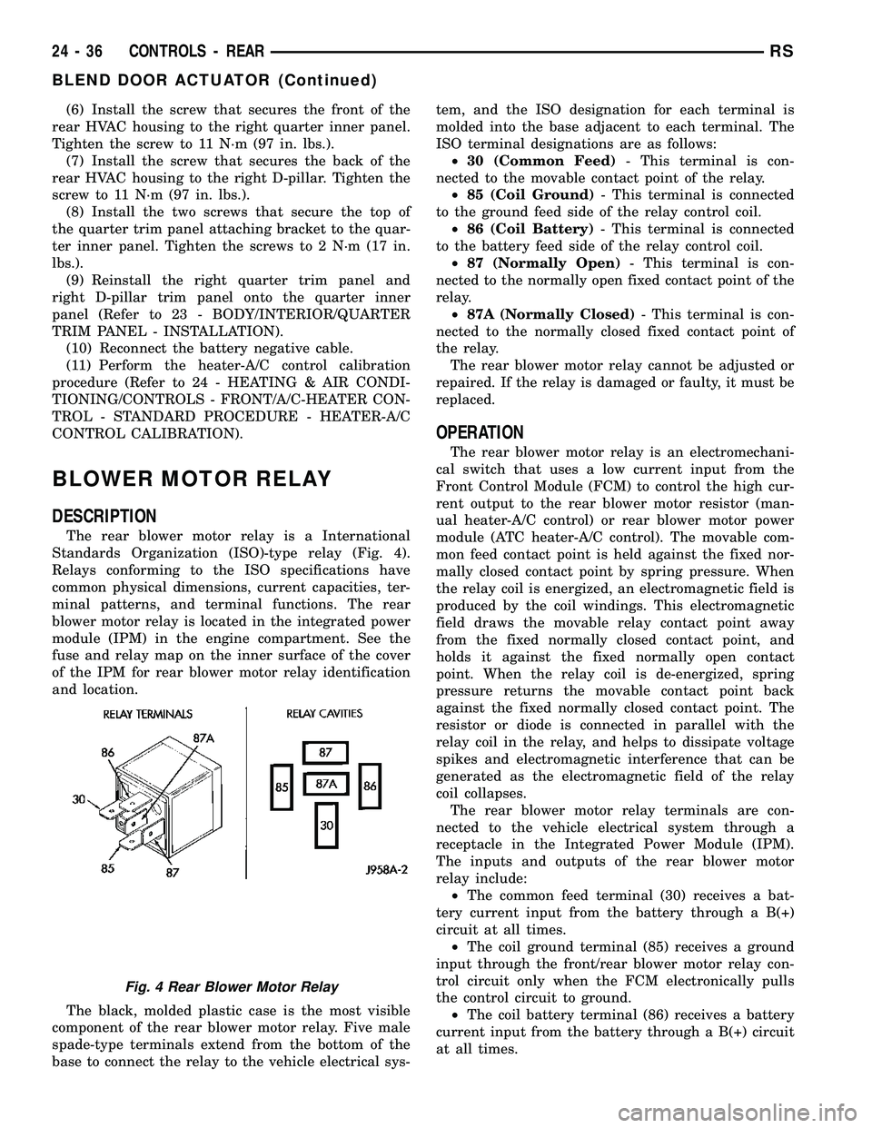
The rear blower motor relay is a International
Standards Organization (ISO)-type relay (Fig. 4).
Relays conforming to the ISO specifications have
common physical dimensions, current capacities, ter-
minal patterns, and terminal functions. The rear
blower motor relay is located in the integrated power
module (IPM) in the engine compartment. See the
fuse and relay map on the inner surface of the cover
of the IPM for rear blower motor relay identification
and location.
The black, molded plastic case is the most visible
component of the rear blower motor relay. Five male
spade-type terminals extend from the bottom of the
base to connect the relay to the vehicle electrical sys-tem, and the ISO designation for each terminal is
molded into the base adjacent to each terminal. The
ISO terminal designations are as follows:
²30 (Common Feed)- This terminal is con-
nected to the movable contact point of the relay.
²85 (Coil Ground)- This terminal is connected
to the ground feed side of the relay control coil.
²86 (Coil Battery)- This terminal is connected
to the battery feed side of the relay control coil.
²87 (Normally Open)- This terminal is con-
nected to the normally open fixed contact point of the
relay.
²87A (Normally Closed)- This terminal is con-
nected to the normally closed fixed contact point of
the relay.
The rear blower motor relay cannot be adjusted or
repaired. If the relay is damaged or faulty, it must be
replaced.
OPERATION
The rear blower motor relay is an electromechani-
cal switch that uses a low current input from the
Front Control Module (FCM) to control the high cur-
rent output to the rear blower motor resistor (man-
ual heater-A/C control) or rear blower motor power
module (ATC heater-A/C control). The movable com-
mon feed contact point is held against the fixed nor-
mally closed contact point by spring pressure. When
the relay coil is energized, an electromagnetic field is
produced by the coil windings. This electromagnetic
field draws the movable relay contact point away
from the fixed normally closed contact point, and
holds it against the fixed normally open contact
point. When the relay coil is de-energized, spring
pressure returns the movable contact point back
against the fixed normally closed contact point. The
resistor or diode is connected in parallel with the
relay coil in the relay, and helps to dissipate voltage
spikes and electromagnetic interference that can be
generated as the electromagnetic field of the relay
coil collapses.
The rear blower motor relay terminals are con-
nected to the vehicle electrical system through a
receptacle in the Integrated Power Module (IPM).
The inputs and outputs of the rear blower motor
relay include:
²The common feed terminal (30) receives a bat-
tery current input from the battery through a B(+)
circuit at all times.
²The coil ground terminal (85) receives a ground
input through the front/rear blower motor relay con-
trol circuit only when the FCM electronically pulls
the control circuit to ground.
²The coil battery terminal (86) receives a battery
current input from the battery through a B(+) circuit
at all times.
Fig. 4 Rear Blower Motor Relay
24 - 36 CONTROLS - REARRS
BLEND DOOR ACTUATOR (Continued)
Page 2188 of 2339
²The normally open terminal (87) provides a bat-
tery current output to the blower motor resistor
(manual heater-A/C control) or blower power module
(ATC heater-A/C control) through a fuse in the IPM
on the fused rear blower motor relay output circuit
only when the blower motor relay coil is energized.
²The normally closed terminal (87A) is not con-
nected to any circuit in this application, but provides
a battery current output only when the rear blower
motor relay coil is de-energized.
Refer to the appropriate wiring information for
diagnosis and testing of the micro-relay and for com-
plete HVAC wiring diagrams.
REMOVAL
(1) Disconnect and isolate the negative battery
cable.
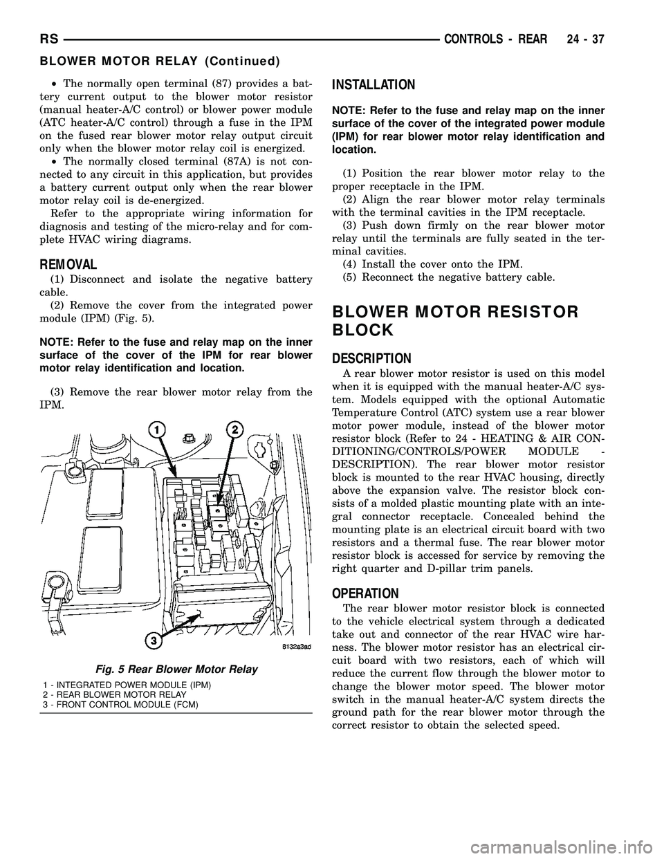
(2) Remove the cover from the integrated power
module (IPM) (Fig. 5).
NOTE: Refer to the fuse and relay map on the inner
surface of the cover of the IPM for rear blower
motor relay identification and location.
(3) Remove the rear blower motor relay from the
IPM.
INSTALLATION
NOTE: Refer to the fuse and relay map on the inner
surface of the cover of the integrated power module
(IPM) for rear blower motor relay identification and
location.
(1) Position the rear blower motor relay to the
proper receptacle in the IPM.
(2) Align the rear blower motor relay terminals
with the terminal cavities in the IPM receptacle.
(3) Push down firmly on the rear blower motor
relay until the terminals are fully seated in the ter-
minal cavities.
(4) Install the cover onto the IPM.
(5) Reconnect the negative battery cable.
BLOWER MOTOR RESISTOR
BLOCK
DESCRIPTION
A rear blower motor resistor is used on this model
when it is equipped with the manual heater-A/C sys-
tem. Models equipped with the optional Automatic
Temperature Control (ATC) system use a rear blower
motor power module, instead of the blower motor
resistor block (Refer to 24 - HEATING & AIR CON-
DITIONING/CONTROLS/POWER MODULE -
DESCRIPTION). The rear blower motor resistor
block is mounted to the rear HVAC housing, directly
above the expansion valve. The resistor block con-
sists of a molded plastic mounting plate with an inte-
gral connector receptacle. Concealed behind the
mounting plate is an electrical circuit board with two
resistors and a thermal fuse. The rear blower motor
resistor block is accessed for service by removing the
right quarter and D-pillar trim panels.
OPERATION
The rear blower motor resistor block is connected
to the vehicle electrical system through a dedicated
take out and connector of the rear HVAC wire har-
ness. The blower motor resistor has an electrical cir-
cuit board with two resistors, each of which will
reduce the current flow through the blower motor to
change the blower motor speed. The blower motor
switch in the manual heater-A/C system directs the
ground path for the rear blower motor through the
correct resistor to obtain the selected speed.
Fig. 5 Rear Blower Motor Relay
1 - INTEGRATED POWER MODULE (IPM)
2 - REAR BLOWER MOTOR RELAY
3 - FRONT CONTROL MODULE (FCM)
RSCONTROLS - REAR24-37
BLOWER MOTOR RELAY (Continued)
Page 2189 of 2339
With the blower motor switch in the lowest speed
position, the ground path for the motor is applied
through both resistors. Each higher speed selected
with the blower motor switch applies the blower
motor ground path through fewer of the resistors,
increasing the blower motor speed. When the blower
motor switch is in the highest speed position, the
blower motor resistors are bypassed and the blower
motor receives a direct path to ground through the
blower motor switch.
The rear blower motor resistor block cannot be
adjusted or repaired and, if faulty or damaged, it
must be replaced.
DIAGNOSIS AND TESTING
REAR BLOWER MOTOR RESISTOR BLOCK
For circuit descriptions and diagrams, refer to the
appropriate wiring information. The wiring informa-
tion includes wiring diagrams, proper wire and con-
nector repair procedures, further details on wire
harness routing and retention, as well as pin-out and
location views for the various wire harness connec-
tors, splices and grounds.
(1) Disconnect and isolate the battery negative
cable.
(2) Disconnect the rear HVAC wire harness con-
nector from the rear blower motor resistor.
(3) Check for continuity between each of the
blower motor switch input terminals of the blower
motor resistor and the resistor output terminal. In
each case there should be continuity. If OK, repair
the wire harness circuits between the blower motor
switch and the blower motor resistor, blower motor or
blower motor relay as required. If not OK, replace
the faulty blower motor resistor block.
REMOVAL
WARNING: THE REAR BLOWER MOTOR RESISTOR
BLOCK MAY GET VERY HOT DURING NORMAL
OPERATION. IF THE BLOWER MOTOR WAS
TURNED ON PRIOR TO SERVICING THE BLOWER
MOTOR RESISTOR BLOCK, WAIT FIVE MINUTES
TO ALLOW THE BLOWER MOTOR RESISTORS TO
COOL BEFORE PERFORMING DIAGNOSIS OR SER-
VICE. FAILURE TO TAKE THIS PRECAUTION CAN
RESULT IN PERSONAL INJURY.CAUTION: Do not operate the blower motor with the
blower motor resistor block removed from the cir-
cuit. Failure to take this precaution can result in
vehicle damage.
(1) Disconnect and isolate the battery negative
cable.
(2) Remove the right quarter trim panel and right
D-pillar trim panel from the quarter inner panel
(Refer to 23 - BODY/INTERIOR/QUARTER TRIM
PANEL - REMOVAL).
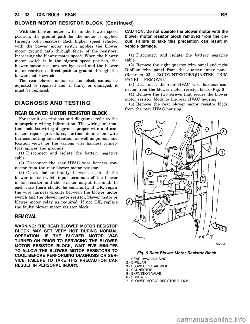
(3) Disconnect the rear HVAC wire harness con-
nector from the blower motor resistor block (Fig. 6).
(4) Remove the two screws that secure the blower
motor resistor block to the rear HVAC housing.
(5) Remove the rear blower motor resistor block
from the rear HVAC housing.
Fig. 6 Rear Blower Motor Resistor Block
1 - REAR HVAC HOUSING
2 - D-PILLAR
3 - BLOWER PIGTAIL WIRE
4 - CONNECTOR
5 - EXPANSION VALVE
6 - SCREW (2)
7 - BLOWER MOTOR RESISTOR BLOCK
24 - 38 CONTROLS - REARRS
BLOWER MOTOR RESISTOR BLOCK (Continued)
Page 2197 of 2339
whenever the ignition switch is in the On position
and the A/C-heater control power is turned on.
The blower motor receives battery current when-
ever the front blower motor relay is energized. The
front blower motor relay output circuit is protected
by a fuse in the Integrated Power Module (IPM)
located in the engine compartment near the battery.
In the manual heater-A/C system, the blower motor
speed is controlled by regulating the path to ground
through the blower control switch and the blower
motor resistor. In the ATC system, the blower motor
speed is controlled by an electronic blower motor
power module, which uses a pulse width modulated
input from the ATC module and feedback from the
blower motor to regulate the blower motor ground
path it provides. The blower motor and wheel are
used to control the velocity of air moving through the
HVAC housing by spinning the blower wheel within
the housing at the selected speed or, in the ATC sys-
tem, at the selected or programmed speed.
DIAGNOSIS AND TESTING
FRONT BLOWER MOTOR
BLOWER MOTOR INOPERATIVE
WARNING: ON VEHICLES EQUIPPED WITH AIR-
BAGS, DISABLE THE AIRBAG SYSTEM BEFORE
ATTEMPTING ANY STEERING WHEEL, STEERING
COLUMN, OR INSTRUMENT PANEL COMPONENT
DIAGNOSIS OR SERVICE. DISCONNECT AND ISO-
LATE THE BATTERY NEGATIVE (GROUND) CABLE,
THEN WAIT TWO MINUTES FOR THE AIRBAG SYS-
TEM CAPACITOR TO DISCHARGE BEFORE PER-
FORMING FURTHER DIAGNOSIS OR SERVICE. THIS
IS THE ONLY SURE WAY TO DISABLE THE AIRBAG
SYSTEM. FAILURE TO TAKE THE PROPER PRE-
CAUTIONS COULD RESULT IN ACCIDENTAL AIR-
BAG DEPLOYMENT AND POSSIBLE PERSONAL
INJURY.
For circuit descriptions and diagrams, refer to the
appropriate wiring information. The wiring informa-
tion includes wiring, diagrams, proper wire and con-
nector repair procedures, further details on wire
harness routing and retention, as well as pin-out and
location views for the various wire harness connec-
tors, splices and grounds.BLOWER MOTOR ELECTRICAL DIAGNOSIS
(1) Check the fuse (Fuse 10 - 40 ampere) in the
Integrated Power Module (IPM). If OK, go to Step 2.
If not OK, repair the shorted circuit or component as
required and replace the faulty fuse.
(2) Turn the ignition switch to the On position. Be
certain that the A/C-heater control power is turned
on. Check for battery voltage at the fuse (Fuse 10 -
40 ampere) in the IPM. If OK, go to Step 3. If not
OK, check the front blower motor relay.
(3) Turn the ignition switch to the Off position.
Disconnect and isolate the battery negative cable.
Disconnect the front HVAC wire harness connector
for the front blower motor resistor block (Manual
Temperature Control) or the front blower motor
power module (Automatic Temperature Control) from
the resistor or module connector receptacle. Recon-
nect the battery negative cable. Turn the ignition
switch to the On position. Be certain that the A/C-
heater control power is turned on. Check for battery
voltage at the fused front blower motor relay output
circuit cavity of the front HVAC wire harness connec-
tor for the front blower motor resistor block (MTC) or
the front blower motor power module (ATC). If OK,
go to Step 4. If not OK, repair the open fused front
blower motor relay output circuit to the IPM as
required.
(4) Turn the ignition switch to the Off position.
Disconnect and isolate the battery negative cable.
Disconnect the front blower motor pigtail wire con-
nector from the connector receptacle of the front
blower motor resistor block (MTC) or the front
blower motor power module (ATC). Use jumper wires
to connect a battery and ground feeds to the blower
motor pigtail wire connector. The blower motor
should operate. If OK with MTC, proceed to diagno-
sis of the front blower motor resistor block (Refer to
24 - HEATING & AIR CONDITIONING/CONTROLS
- FRONT/BLOWER MOTOR RESISTOR - DIAGNO-
SIS AND TESTING). If OK with ATC, use a DRBIII
scan tool to diagnose the front blower motor power
module. Refer to Body Diagnostic information. If not
OK with MTC or ATC, replace the faulty front blower
motor.
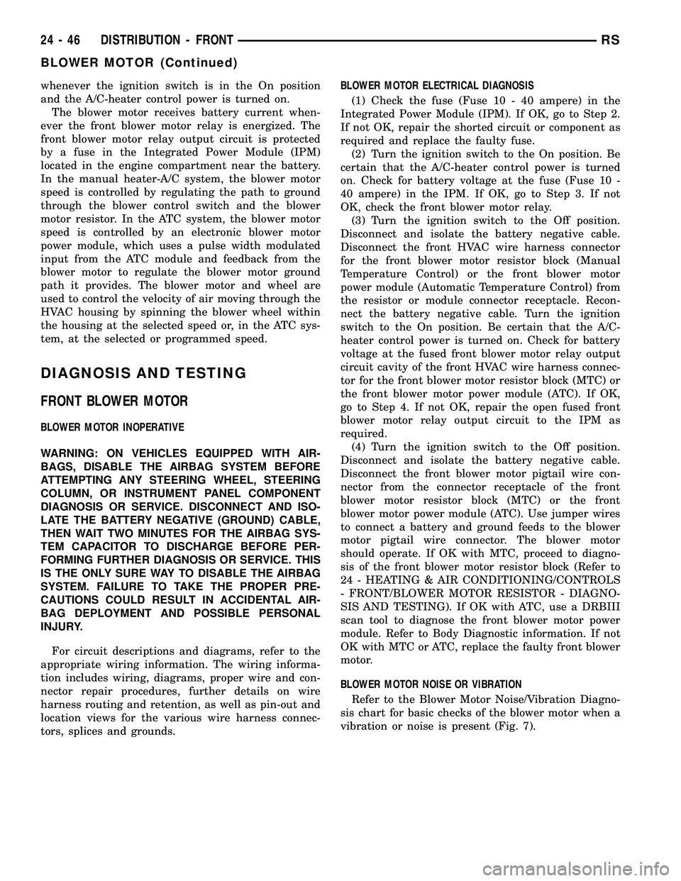
BLOWER MOTOR NOISE OR VIBRATION
Refer to the Blower Motor Noise/Vibration Diagno-
sis chart for basic checks of the blower motor when a
vibration or noise is present (Fig. 7).
24 - 46 DISTRIBUTION - FRONTRS
BLOWER MOTOR (Continued)
Page 2200 of 2339
(12) Gently flex the recirculation air door far down
enough to remove the blower motor and wheel from
the HVAC housing.
(13) Remove the blower motor and wheel from the
HVAC housing. Note the position of the blower motor
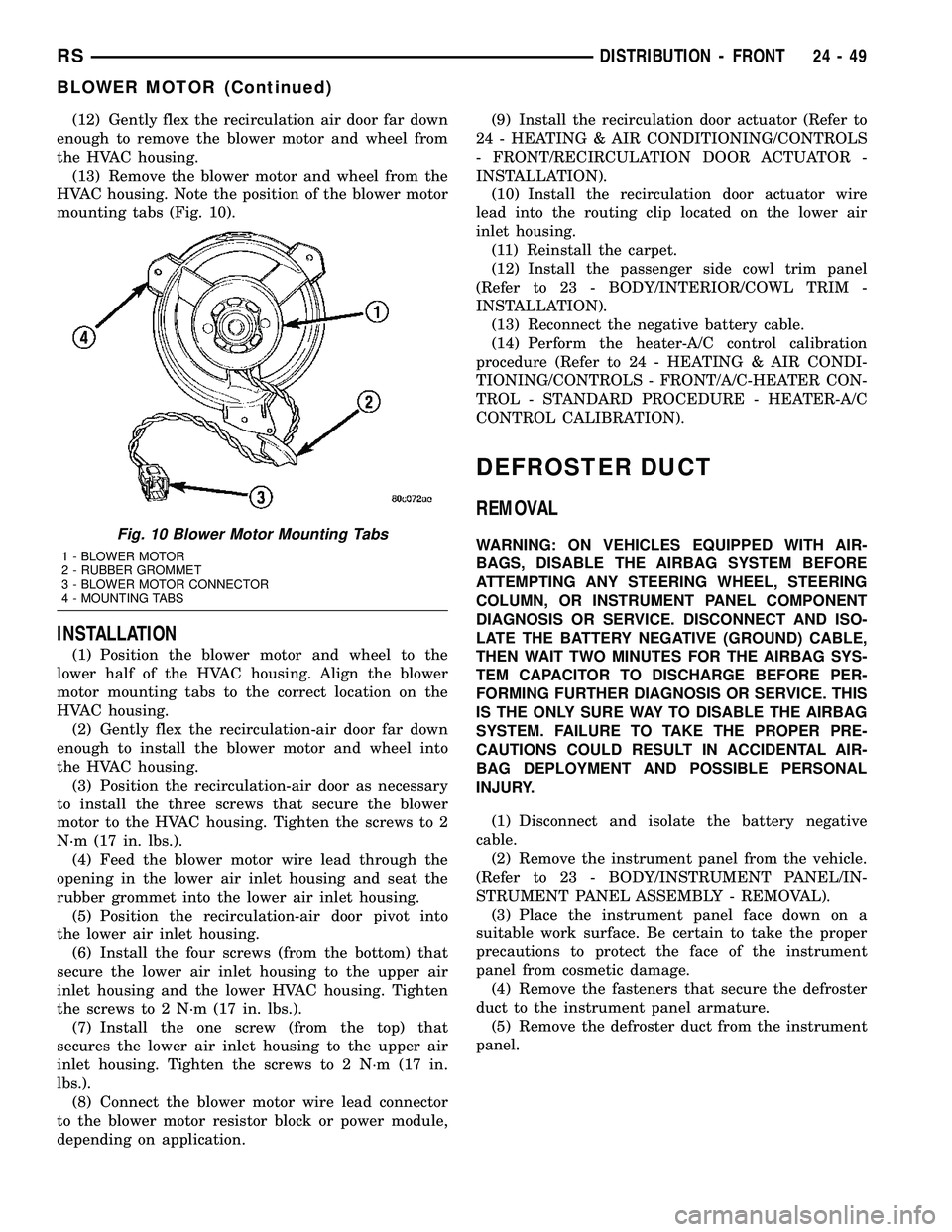
mounting tabs (Fig. 10).
INSTALLATION
(1) Position the blower motor and wheel to the
lower half of the HVAC housing. Align the blower
motor mounting tabs to the correct location on the
HVAC housing.
(2) Gently flex the recirculation-air door far down
enough to install the blower motor and wheel into
the HVAC housing.
(3) Position the recirculation-air door as necessary
to install the three screws that secure the blower
motor to the HVAC housing. Tighten the screws to 2
N´m (17 in. lbs.).
(4) Feed the blower motor wire lead through the
opening in the lower air inlet housing and seat the
rubber grommet into the lower air inlet housing.
(5) Position the recirculation-air door pivot into
the lower air inlet housing.
(6) Install the four screws (from the bottom) that
secure the lower air inlet housing to the upper air
inlet housing and the lower HVAC housing. Tighten
the screws to 2 N´m (17 in. lbs.).
(7) Install the one screw (from the top) that
secures the lower air inlet housing to the upper air
inlet housing. Tighten the screws to 2 N´m (17 in.
lbs.).
(8) Connect the blower motor wire lead connector
to the blower motor resistor block or power module,
depending on application.(9) Install the recirculation door actuator (Refer to
24 - HEATING & AIR CONDITIONING/CONTROLS
- FRONT/RECIRCULATION DOOR ACTUATOR -
INSTALLATION).
(10) Install the recirculation door actuator wire
lead into the routing clip located on the lower air
inlet housing.
(11) Reinstall the carpet.
(12) Install the passenger side cowl trim panel
(Refer to 23 - BODY/INTERIOR/COWL TRIM -
INSTALLATION).
(13) Reconnect the negative battery cable.
(14) Perform the heater-A/C control calibration
procedure (Refer to 24 - HEATING & AIR CONDI-
TIONING/CONTROLS - FRONT/A/C-HEATER CON-
TROL - STANDARD PROCEDURE - HEATER-A/C
CONTROL CALIBRATION).
DEFROSTER DUCT
REMOVAL
WARNING: ON VEHICLES EQUIPPED WITH AIR-
BAGS, DISABLE THE AIRBAG SYSTEM BEFORE
ATTEMPTING ANY STEERING WHEEL, STEERING
COLUMN, OR INSTRUMENT PANEL COMPONENT
DIAGNOSIS OR SERVICE. DISCONNECT AND ISO-
LATE THE BATTERY NEGATIVE (GROUND) CABLE,
THEN WAIT TWO MINUTES FOR THE AIRBAG SYS-
TEM CAPACITOR TO DISCHARGE BEFORE PER-
FORMING FURTHER DIAGNOSIS OR SERVICE. THIS
IS THE ONLY SURE WAY TO DISABLE THE AIRBAG
SYSTEM. FAILURE TO TAKE THE PROPER PRE-
CAUTIONS COULD RESULT IN ACCIDENTAL AIR-
BAG DEPLOYMENT AND POSSIBLE PERSONAL
INJURY.
(1) Disconnect and isolate the battery negative
cable.
(2) Remove the instrument panel from the vehicle.
(Refer to 23 - BODY/INSTRUMENT PANEL/IN-
STRUMENT PANEL ASSEMBLY - REMOVAL).
(3) Place the instrument panel face down on a
suitable work surface. Be certain to take the proper
precautions to protect the face of the instrument
panel from cosmetic damage.
(4) Remove the fasteners that secure the defroster
duct to the instrument panel armature.
(5) Remove the defroster duct from the instrument
panel.Fig. 10 Blower Motor Mounting Tabs
1 - BLOWER MOTOR
2 - RUBBER GROMMET
3 - BLOWER MOTOR CONNECTOR
4 - MOUNTING TABS
RSDISTRIBUTION - FRONT24-49
BLOWER MOTOR (Continued)
Page 2209 of 2339
DIAGNOSIS AND TESTING
REAR BLOWER MOTOR
BLOWER MOTOR INOPERATIVE
For circuit descriptions and diagrams, refer to the
appropriate wiring information. The wiring informa-
tion includes wiring, diagrams, proper wire and con-
nector repair procedures, further details on wire
harness routing and retention, as well as pin-out and
location views for the various wire harness connec-
tors, splices and grounds.
BLOWER MOTOR ELECTRICAL DIAGNOSIS
(1) Check the fuse (Fuse 12 - 25 ampere) in the
Integrated Power Module (IPM). If OK, go to Step 2.
If not OK, repair the shorted circuit or component as
required and replace the faulty fuse.
(2) Turn the ignition switch to the On position. Be
certain that the rear A/C-heater control power is
turned on. Check for battery voltage at the fuse
(Fuse 12 - 25 ampere) in the IPM. If OK, go to Step
3. If not OK, check the rear blower motor relay.
(3) Turn the ignition switch to the Off position.
Disconnect and isolate the battery negative cable.
Disconnect the rear HVAC wire harness connector
from the rear blower motor resistor block (Manual
Temperature Control) or the rear blower motor power
module (Automatic Temperature Control). Reconnect
the battery negative cable. Turn the ignition switch
to the On position. Be certain that the rear A/C-
heater control power is turned on. Check for battery
voltage at the fused rear blower motor relay output
circuit cavity of the rear HVAC wire harness connec-
tor for the rear blower motor resistor block (MTC) or
the rear blower motor power module (ATC). If OK, go
to Step 4. If not OK, repair the open fused front
blower motor relay output circuit to the IPM as
required.
(4) Turn the ignition switch to the Off position.
Disconnect and isolate the battery negative cable.Disconnect the rear blower motor pigtail wire connec-
tor from the rear HVAC wire harness (MTC) or the
rear blower power module (ATC). Use jumper wires
to connect a battery and ground feeds to the blower
motor pigtail wire connector. The rear blower motor
should operate. If OK with MTC, proceed to diagno-
sis of the rear blower motor resistor block (Refer to
24 - HEATING & AIR CONDITIONING/CONTROLS
- REAR/BLOWER MOTOR RESISTOR - DIAGNOSIS
AND TESTING). If OK with ATC, use a DRBIII scan
tool to diagnose the rear blower motor power module.
Refer to the appropriate diagnostic information. If
not OK with MTC or ATC, replace the faulty rear
blower motor.
BLOWER MOTOR NOISE OR VIBRATION
Refer to the Blower Motor Noise/Vibration Diagno-
sis chart for basic checks of the blower motor when a
vibration or noise is present (Fig. 3).
REMOVAL
WARNING: REFER TO THE APPLICABLE WARN-
INGS AND CAUTIONS FOR THIS SYSTEM BEFORE
PERFORMING THE FOLLOWING OPERATION (Refer
to 24 - HEATING & AIR CONDITIONING/PLUMBING -
WARNING) and (Refer to 24 - HEATING & AIR CON-
DITIONING/PLUMBING - CAUTION).
(1) Remove the rear HVAC housing from the vehi-
cle (Refer to 24 - HEATING & AIR CONDITIONING/
DISTRIBUTION/HVAC HOUSING - REMOVAL).
(2) Disconnect the rear blower motor pigtail wire
connector.
NOTE: With the Manual Temperature Control sys-
tem, the blower motor pigtail wire is connected to a
take out and connector of the rear HVAC wire har-
ness. With the Automatic Temperature Control sys-
tem , the blower pigtail wire is connected to a
receptacle on the blower motor power module.
24 - 58 DISTRIBUTION - REARRS
BLOWER MOTOR (Continued)
Page 2237 of 2339
(3) Align the engine compartment ends of both
heater core tubes with the openings in the dash
panel seal and push them simultaneously forward
through the seal far enough to engage the heater
core ends of the tubes with the heater core supply
and return ports.
(4) Position both heater core tubes and the sealing
plate simultaneously to the heater core supply and
return ports.
NOTE: The heater core tubes each have a slot that
must be indexed to a location tab within each of the
heater core ports. Adjust the position of the tubes
as required so that the sealing plate fits flush
against the heater core supply and return ports,
which indicates that the tubes are properly indexed.
(5) Index both heater core tubes to the heater core
ports.
(6) Install the screw that secures the heater core
tube sealing plate to the heater core supply and
return ports. Tighten the screw to 3 N´m (27 in. lbs.).
(7) Install the silencer under the driver side end of
the instrument panel.
(8) Connect the heater hoses to the heater hose
tubes (Refer to 24 - HEATING & AIR CONDITION-
ING/PLUMBING/HEATER INLET HOSE - INSTAL-
LATION) and(Refer to 24 - HEATING & AIR
CONDITIONING/PLUMBING/HEATER RETURN
HOSE - INSTALLATION).
(9) Reconnect the battery negative cable.
(10) Refill the engine cooling system (Refer to 7 -
COOLING - STANDARD PROCEDURE - COOLING
SYSTEM REFILL).
FRONT HEATER CORE
(1) While pushing the brake pedal downward and
pulling the accelerator pedal upward far enough for
clearance, slide the heater core into the distribution
housing.
(2) Install the two screws that secure the heater
core mounting plate to the distribution housing.
Tighten the screws to 2 N´m (17 in. lbs.).(3) Install the heater core tubes (Refer to 24 -
HEATING & AIR CONDITIONING/PLUMBING/
HEATER CORE - INSTALLATION).
(4) Reconnect the power brake booster input rod
(push rod) to the pin on the brake pedal arm (Refer
to 5 - BRAKES/HYDRAULIC/MECHANICAL/
POWER BRAKE BOOSTER - INSTALLATION).
(5) Reinstall the brake lamp switch into its mount-
ing bracket (Refer to 8 - ELECTRICAL/LAMPS/
LIGHTING - EXTERIOR/BRAKE LAMP SWITCH -
INSTALLATION).
(6) Reinstall the silencer boot around the base of
the lower steering shaft on the dash panel.
(7) Reconnect the battery negative cable.
(8) Refill the engine cooling system (Refer to 7 -
COOLING - STANDARD PROCEDURE - COOLING
SYSTEM REFILL).
(9) Operate system for two thermostat cycles to
assure the elimination of any air that may be
trapped within the cooling system.
HEATER INLET HOSE
REMOVAL
WARNING: REFER TO THE APPLICABLE WARN-
INGS AND CAUTIONS FOR THIS SYSTEM BEFORE
PERFORMING THE FOLLOWING OPERATION (Refer
to 24 - HEATING & AIR CONDITIONING/PLUMBING -
WARNING).
NOTE: The heater inlet hose is constructed from
formed steel tubing and rubber hoses. Depending
on application, the ends are secured to the heater
core, engine oil cooler or the engine by spring ten-
sion clamps.
(1) Drain the engine cooling system (Refer to 7 -
COOLING - STANDARD PROCEDURE - COOLING
SYSTEM DRAIN).
24 - 86 PLUMBING - FRONTRS
HEATER CORE (Continued)
Page 2287 of 2339
NATURAL VAC LEAK
DETECTION ASSY
REMOVAL
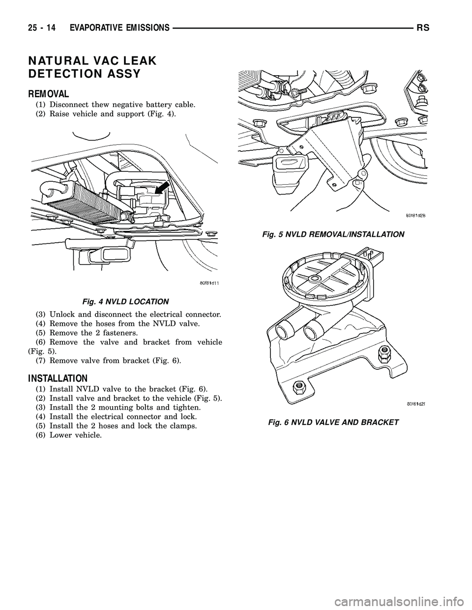
(1) Disconnect thew negative battery cable.
(2) Raise vehicle and support (Fig. 4).
(3) Unlock and disconnect the electrical connector.
(4) Remove the hoses from the NVLD valve.
(5) Remove the 2 fasteners.
(6) Remove the valve and bracket from vehicle
(Fig. 5).
(7) Remove valve from bracket (Fig. 6).
INSTALLATION
(1) Install NVLD valve to the bracket (Fig. 6).
(2) Install valve and bracket to the vehicle (Fig. 5).
(3) Install the 2 mounting bolts and tighten.
(4) Install the electrical connector and lock.
(5) Install the 2 hoses and lock the clamps.
(6) Lower vehicle.
Fig. 4 NVLD LOCATION
Fig. 5 NVLD REMOVAL/INSTALLATION
Fig. 6 NVLD VALVE AND BRACKET
25 - 14 EVAPORATIVE EMISSIONSRS