2005 CHRYSLER CARAVAN transmission oil
[x] Cancel search: transmission oilPage 1693 of 2339
FLUID/FILTER SERVICE (RECOMMENDED)
(1) Raise vehicle on a hoist. Refer to LUBRICA-
TION and MAINTENANCE for proper procedures.
Place a drain container with a large opening, under
transaxle oil pan.
(2) Loosen pan bolts and tap the pan at one corner
to break it loose allowing fluid to drain, then remove
the oil pan.
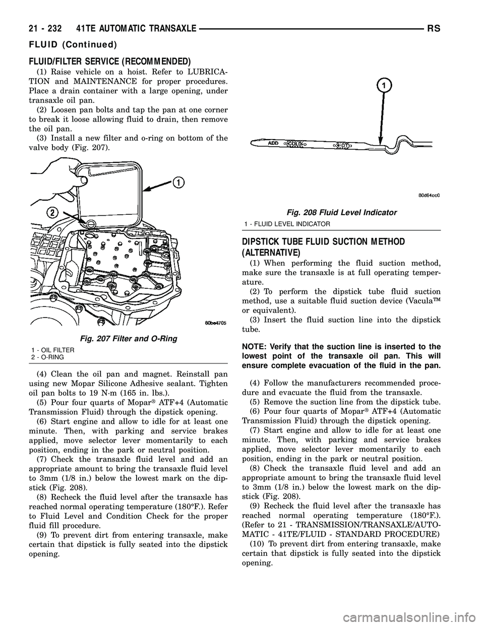
(3) Install a new filter and o-ring on bottom of the
valve body (Fig. 207).
(4) Clean the oil pan and magnet. Reinstall pan
using new Mopar Silicone Adhesive sealant. Tighten
oil pan bolts to 19 N´m (165 in. lbs.).
(5) Pour four quarts of MopartATF+4 (Automatic
Transmission Fluid) through the dipstick opening.
(6) Start engine and allow to idle for at least one
minute. Then, with parking and service brakes
applied, move selector lever momentarily to each
position, ending in the park or neutral position.
(7) Check the transaxle fluid level and add an
appropriate amount to bring the transaxle fluid level
to 3mm (1/8 in.) below the lowest mark on the dip-
stick (Fig. 208).
(8) Recheck the fluid level after the transaxle has
reached normal operating temperature (180ÉF.). Refer
to Fluid Level and Condition Check for the proper
fluid fill procedure.
(9) To prevent dirt from entering transaxle, make
certain that dipstick is fully seated into the dipstick
opening.
DIPSTICK TUBE FLUID SUCTION METHOD
(ALTERNATIVE)
(1) When performing the fluid suction method,
make sure the transaxle is at full operating temper-
ature.
(2) To perform the dipstick tube fluid suction
method, use a suitable fluid suction device (VaculaŸ
or equivalent).
(3) Insert the fluid suction line into the dipstick
tube.
NOTE: Verify that the suction line is inserted to the
lowest point of the transaxle oil pan. This will
ensure complete evacuation of the fluid in the pan.
(4) Follow the manufacturers recommended proce-
dure and evacuate the fluid from the transaxle.
(5) Remove the suction line from the dipstick tube.
(6) Pour four quarts of MopartATF+4 (Automatic
Transmission Fluid) through the dipstick opening.
(7) Start engine and allow to idle for at least one
minute. Then, with parking and service brakes
applied, move selector lever momentarily to each
position, ending in the park or neutral position.
(8) Check the transaxle fluid level and add an
appropriate amount to bring the transaxle fluid level
to 3mm (1/8 in.) below the lowest mark on the dip-
stick (Fig. 208).
(9) Recheck the fluid level after the transaxle has
reached normal operating temperature (180ÉF.).
(Refer to 21 - TRANSMISSION/TRANSAXLE/AUTO-
MATIC - 41TE/FLUID - STANDARD PROCEDURE)
(10) To prevent dirt from entering transaxle, make
certain that dipstick is fully seated into the dipstick
opening.
Fig. 207 Filter and O-Ring
1 - OIL FILTER
2 - O-RING
Fig. 208 Fluid Level Indicator
1 - FLUID LEVEL INDICATOR
21 - 232 41TE AUTOMATIC TRANSAXLERS
FLUID (Continued)
Page 1724 of 2339
(8) Position an appropriate piece of Plastigage
across both pump gears.
(9) Align the Plastigage to a flat area on the reac-
tion shaft support housing.
(10) Install the reaction shaft to the pump housing
(Fig. 280). Tighten the bolts to 27 N´m (20 ft. lbs.).
(11) Remove bolts and carefully separate the hous-
ings. Measure the Plastigage following the instruc-
tions supplied.
(12) Clearance between both gear end faces and
the reaction shaft support should be 0.020-0.046 mm
(0.0008-0.0018 in.).
ASSEMBLY
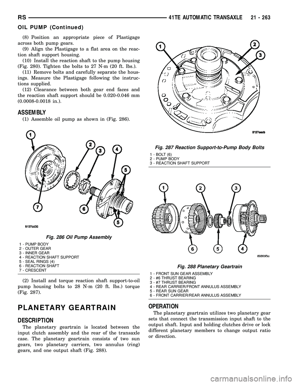
(1) Assemble oil pump as shown in (Fig. 286).
(2) Install and torque reaction shaft support-to-oil
pump housing bolts to 28 N´m (20 ft. lbs.) torque
(Fig. 287).
PLANETARY GEARTRAIN
DESCRIPTION
The planetary geartrain is located between the
input clutch assembly and the rear of the transaxle
case. The planetary geartrain consists of two sun
gears, two planetary carriers, two annulus (ring)
gears, and one output shaft (Fig. 288).
OPERATION
The planetary geartrain utilizes two planetary gear
sets that connect the transmission input shaft to the
output shaft. Input and holding clutches drive or lock
different planetary members to change output ratio
or direction.
Fig. 286 Oil Pump Assembly
1 - PUMP BODY
2 - OUTER GEAR
3 - INNER GEAR
4 - REACTION SHAFT SUPPORT
5 - SEAL RINGS (4)
6 - REACTION SHAFT
7 - CRESCENT
Fig. 287 Reaction Support-to-Pump Body Bolts
1 - BOLT (6)
2 - PUMP BODY
3 - REACTION SHAFT SUPPORT
Fig. 288 Planetary Geartrain
1 - FRONT SUN GEAR ASSEMBLY
2 - #6 THRUST BEARING
3 - #7 THRUST BEARING
4 - REAR CARRIER/FRONT ANNULUS ASSEMBLY
5 - REAR SUN GEAR
6 - FRONT CARRIER/REAR ANNULUS ASSEMBLY
RS41TE AUTOMATIC TRANSAXLE21 - 263
OIL PUMP (Continued)
Page 1725 of 2339
SEAL - OIL PUMP
REMOVAL
(1) Remove transaxle from vehicle (Refer to 21 -
TRANSMISSION/TRANSAXLE/AUTOMATIC - 41TE
- REMOVAL).
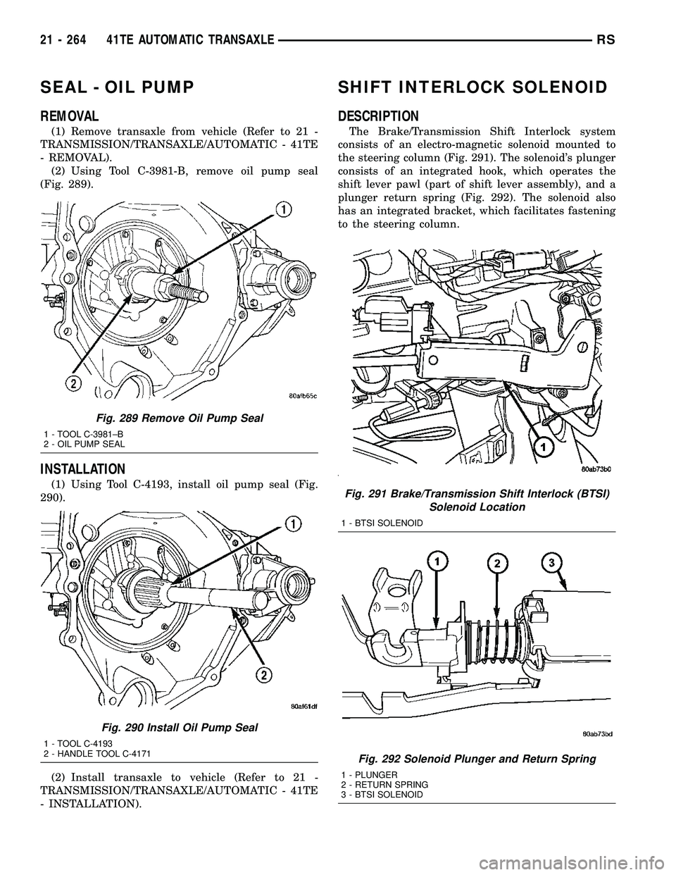
(2) Using Tool C-3981-B, remove oil pump seal
(Fig. 289).
INSTALLATION
(1) Using Tool C-4193, install oil pump seal (Fig.
290).
(2) Install transaxle to vehicle (Refer to 21 -
TRANSMISSION/TRANSAXLE/AUTOMATIC - 41TE
- INSTALLATION).
SHIFT INTERLOCK SOLENOID
DESCRIPTION
The Brake/Transmission Shift Interlock system
consists of an electro-magnetic solenoid mounted to
the steering column (Fig. 291). The solenoid's plunger
consists of an integrated hook, which operates the
shift lever pawl (part of shift lever assembly), and a
plunger return spring (Fig. 292). The solenoid also
has an integrated bracket, which facilitates fastening
to the steering column.
Fig. 289 Remove Oil Pump Seal
1 - TOOL C-3981±B
2 - OIL PUMP SEAL
Fig. 290 Install Oil Pump Seal
1 - TOOL C-4193
2 - HANDLE TOOL C-4171
Fig. 291 Brake/Transmission Shift Interlock (BTSI)
Solenoid Location
1 - BTSI SOLENOID
Fig. 292 Solenoid Plunger and Return Spring
1 - PLUNGER
2 - RETURN SPRING
3 - BTSI SOLENOID
21 - 264 41TE AUTOMATIC TRANSAXLERS
Page 1732 of 2339
SPEED SENSOR - INPUT
DESCRIPTION
The Input Speed Sensor is a two-wire magnetic
pickup device that generates AC signals as rotation
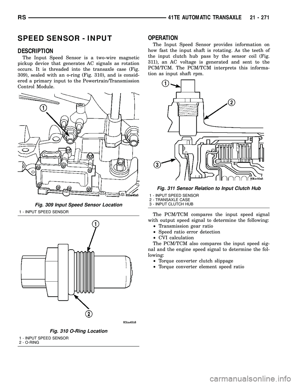
occurs. It is threaded into the transaxle case (Fig.
309), sealed with an o-ring (Fig. 310), and is consid-
ered a primary input to the Powertrain/Transmission
Control Module.
OPERATION
The Input Speed Sensor provides information on
how fast the input shaft is rotating. As the teeth of
the input clutch hub pass by the sensor coil (Fig.
311), an AC voltage is generated and sent to the
PCM/TCM. The PCM/TCM interprets this informa-
tion as input shaft rpm.
The PCM/TCM compares the input speed signal
with output speed signal to determine the following:
²Transmission gear ratio
²Speed ratio error detection
²CVI calculation
The PCM/TCM also compares the input speed sig-
nal and the engine speed signal to determine the fol-
lowing:
²Torque converter clutch slippage
²Torque converter element speed ratio
Fig. 309 Input Speed Sensor Location
1 - INPUT SPEED SENSOR
Fig. 310 O-Ring Location
1 - INPUT SPEED SENSOR
2 - O-RING
Fig. 311 Sensor Relation to Input Clutch Hub
1 - INPUT SPEED SENSOR
2 - TRANSAXLE CASE
3 - INPUT CLUTCH HUB
RS41TE AUTOMATIC TRANSAXLE21 - 271
Page 1734 of 2339
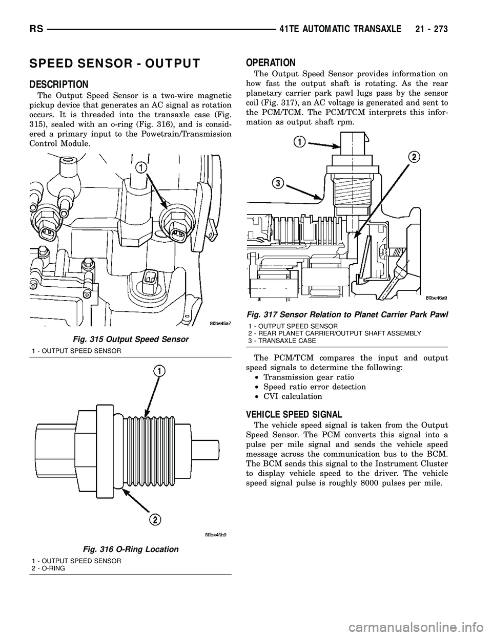
SPEED SENSOR - OUTPUT
DESCRIPTION
The Output Speed Sensor is a two-wire magnetic
pickup device that generates an AC signal as rotation
occurs. It is threaded into the transaxle case (Fig.
315), sealed with an o-ring (Fig. 316), and is consid-
ered a primary input to the Powetrain/Transmission
Control Module.
OPERATION
The Output Speed Sensor provides information on
how fast the output shaft is rotating. As the rear
planetary carrier park pawl lugs pass by the sensor
coil (Fig. 317), an AC voltage is generated and sent to
the PCM/TCM. The PCM/TCM interprets this infor-
mation as output shaft rpm.
The PCM/TCM compares the input and output
speed signals to determine the following:
²Transmission gear ratio
²Speed ratio error detection
²CVI calculation
VEHICLE SPEED SIGNAL
The vehicle speed signal is taken from the Output
Speed Sensor. The PCM converts this signal into a
pulse per mile signal and sends the vehicle speed
message across the communication bus to the BCM.
The BCM sends this signal to the Instrument Cluster
to display vehicle speed to the driver. The vehicle
speed signal pulse is roughly 8000 pulses per mile.
Fig. 315 Output Speed Sensor
1 - OUTPUT SPEED SENSOR
Fig. 316 O-Ring Location
1 - OUTPUT SPEED SENSOR
2 - O-RING
Fig. 317 Sensor Relation to Planet Carrier Park Pawl
1 - OUTPUT SPEED SENSOR
2 - REAR PLANET CARRIER/OUTPUT SHAFT ASSEMBLY
3 - TRANSAXLE CASE
RS41TE AUTOMATIC TRANSAXLE21 - 273
Page 1736 of 2339
TORQUE CONVERTER
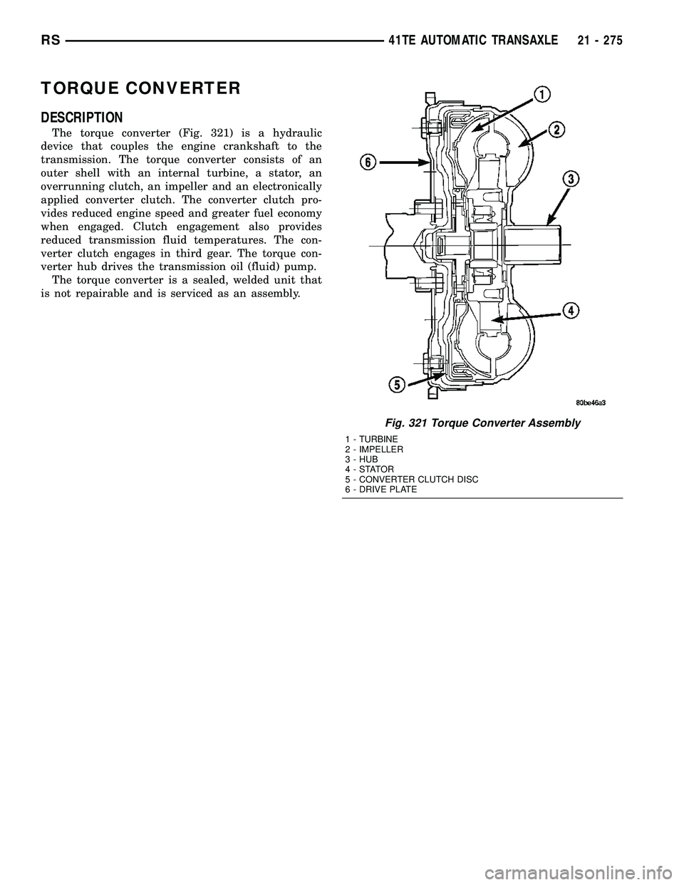
DESCRIPTION
The torque converter (Fig. 321) is a hydraulic
device that couples the engine crankshaft to the
transmission. The torque converter consists of an
outer shell with an internal turbine, a stator, an
overrunning clutch, an impeller and an electronically
applied converter clutch. The converter clutch pro-
vides reduced engine speed and greater fuel economy
when engaged. Clutch engagement also provides
reduced transmission fluid temperatures. The con-
verter clutch engages in third gear. The torque con-
verter hub drives the transmission oil (fluid) pump.
The torque converter is a sealed, welded unit that
is not repairable and is serviced as an assembly.
Fig. 321 Torque Converter Assembly
1 - TURBINE
2 - IMPELLER
3 - HUB
4-STATOR
5 - CONVERTER CLUTCH DISC
6 - DRIVE PLATE
RS41TE AUTOMATIC TRANSAXLE21 - 275
Page 1737 of 2339
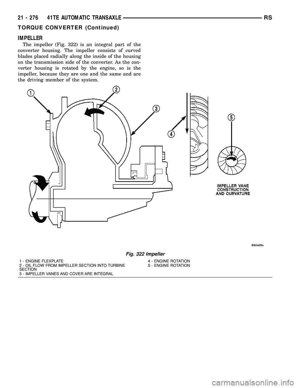
IMPELLER
The impeller (Fig. 322) is an integral part of the
converter housing. The impeller consists of curved
blades placed radially along the inside of the housing
on the transmission side of the converter. As the con-
verter housing is rotated by the engine, so is the
impeller, because they are one and the same and are
the driving member of the system.
Fig. 322 Impeller
1 - ENGINE FLEXPLATE 4 - ENGINE ROTATION
2 - OIL FLOW FROM IMPELLER SECTION INTO TURBINE
SECTION5 - ENGINE ROTATION
3 - IMPELLER VANES AND COVER ARE INTEGRAL
21 - 276 41TE AUTOMATIC TRANSAXLERS
TORQUE CONVERTER (Continued)
Page 1739 of 2339
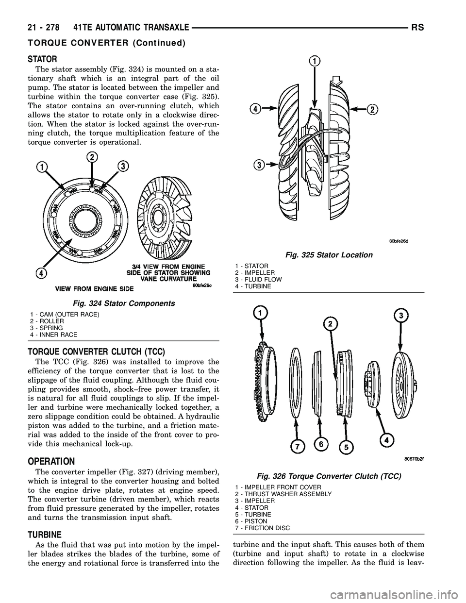
STATOR
The stator assembly (Fig. 324) is mounted on a sta-
tionary shaft which is an integral part of the oil
pump. The stator is located between the impeller and
turbine within the torque converter case (Fig. 325).
The stator contains an over-running clutch, which
allows the stator to rotate only in a clockwise direc-
tion. When the stator is locked against the over-run-
ning clutch, the torque multiplication feature of the
torque converter is operational.
TORQUE CONVERTER CLUTCH (TCC)
The TCC (Fig. 326) was installed to improve the
efficiency of the torque converter that is lost to the
slippage of the fluid coupling. Although the fluid cou-
pling provides smooth, shock±free power transfer, it
is natural for all fluid couplings to slip. If the impel-
ler and turbine were mechanically locked together, a
zero slippage condition could be obtained. A hydraulic
piston was added to the turbine, and a friction mate-
rial was added to the inside of the front cover to pro-
vide this mechanical lock-up.
OPERATION
The converter impeller (Fig. 327) (driving member),
which is integral to the converter housing and bolted
to the engine drive plate, rotates at engine speed.
The converter turbine (driven member), which reacts
from fluid pressure generated by the impeller, rotates
and turns the transmission input shaft.
TURBINE
As the fluid that was put into motion by the impel-
ler blades strikes the blades of the turbine, some of
the energy and rotational force is transferred into theturbine and the input shaft. This causes both of them
(turbine and input shaft) to rotate in a clockwise
direction following the impeller. As the fluid is leav-
Fig. 324 Stator Components
1 - CAM (OUTER RACE)
2 - ROLLER
3 - SPRING
4 - INNER RACE
Fig. 325 Stator Location
1-STATOR
2 - IMPELLER
3 - FLUID FLOW
4 - TURBINE
Fig. 326 Torque Converter Clutch (TCC)
1 - IMPELLER FRONT COVER
2 - THRUST WASHER ASSEMBLY
3 - IMPELLER
4-STATOR
5 - TURBINE
6 - PISTON
7 - FRICTION DISC
21 - 278 41TE AUTOMATIC TRANSAXLERS
TORQUE CONVERTER (Continued)