2005 CHRYSLER CARAVAN suspension
[x] Cancel search: suspensionPage 1453 of 2339
HOSE - POWER STEERING
PRESSURE
REMOVAL
REMOVAL - 2.4L ENGINE
NOTE: Before proceeding, review all WARNINGS
and CAUTIONS. (Refer to 19 - STEERING/PUMP -
WARNING)(Refer to 19 - STEERING/PUMP - CAU-
TION)
(1) Remove cap from power steering fluid reser-
voir.
(2) Using a siphon pump, remove as much power
steering fluid as possible from power steering fluid
reservoir.
(3) Raise vehicle. (Refer to LUBRICATION &
MAINTENANCE/HOISTING - STANDARD PROCE-
DURE)
(4) Remove front emissions vapor canister. (Refer
to 25 - EMISSIONS CONTROL/EVAPORATIVE
EMISSIONS/VAPOR CANISTER - REMOVAL)
(5) Place an oil drain pan under vehicle to catch
power steering fluid.
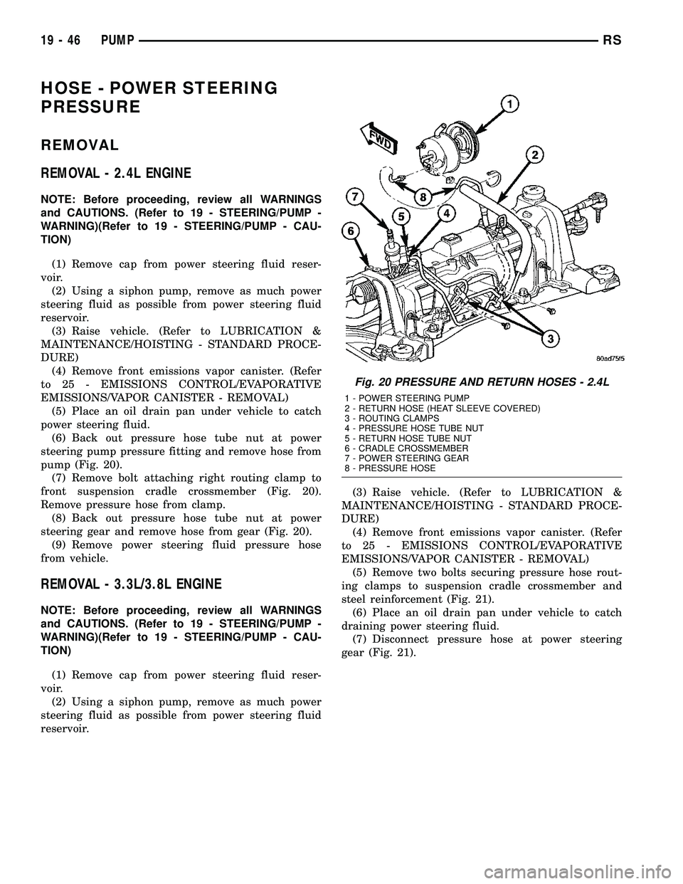
(6) Back out pressure hose tube nut at power
steering pump pressure fitting and remove hose from
pump (Fig. 20).
(7) Remove bolt attaching right routing clamp to
front suspension cradle crossmember (Fig. 20).
Remove pressure hose from clamp.
(8) Back out pressure hose tube nut at power
steering gear and remove hose from gear (Fig. 20).
(9) Remove power steering fluid pressure hose
from vehicle.
REMOVAL - 3.3L/3.8L ENGINE
NOTE: Before proceeding, review all WARNINGS
and CAUTIONS. (Refer to 19 - STEERING/PUMP -
WARNING)(Refer to 19 - STEERING/PUMP - CAU-
TION)
(1) Remove cap from power steering fluid reser-
voir.
(2) Using a siphon pump, remove as much power
steering fluid as possible from power steering fluid
reservoir.(3) Raise vehicle. (Refer to LUBRICATION &
MAINTENANCE/HOISTING - STANDARD PROCE-
DURE)
(4) Remove front emissions vapor canister. (Refer
to 25 - EMISSIONS CONTROL/EVAPORATIVE
EMISSIONS/VAPOR CANISTER - REMOVAL)
(5) Remove two bolts securing pressure hose rout-
ing clamps to suspension cradle crossmember and
steel reinforcement (Fig. 21).
(6) Place an oil drain pan under vehicle to catch
draining power steering fluid.
(7) Disconnect pressure hose at power steering
gear (Fig. 21).
Fig. 20 PRESSURE AND RETURN HOSES - 2.4L
1 - POWER STEERING PUMP
2 - RETURN HOSE (HEAT SLEEVE COVERED)
3 - ROUTING CLAMPS
4 - PRESSURE HOSE TUBE NUT
5 - RETURN HOSE TUBE NUT
6 - CRADLE CROSSMEMBER
7 - POWER STEERING GEAR
8 - PRESSURE HOSE
19 - 46 PUMPRS
Page 1456 of 2339
(3) Install new O-rings on ends of power steering
fluid pressure hose. Lubricate O-rings using clean
power steering fluid.
CAUTION: Use care not to bend tube ends of the
power steering hoses when installing. Leaks and
restrictions may occur.
CAUTION: Power steering fluid hoses must remain
away from the exhaust system and must not come
in contact with any unfriendly surfaces on the vehi-
cle.
(4) Route hose up behind engine toward pump
avoiding tight bends or kinking.
(5) Install power steering pressure hose end into
pump pressure outlet fitting (Fig. 22). Thread tube
nut into outlet fitting, but do not tighten at this time.
(6) Attach pressure hose routing bracket to engine
(Fig. 22). Tighten bolt to 23 N´m (200 in. lbs.) torque.
(7) Tighten hose tube nut at pump outlet fitting to
31 N´m (275 in. lbs.) torque.
(8) Route hose behind cradle crossmember and
start hose end into gear port. Do not tighten hose
tube nut at this time.
(9) Attach hose to suspension cradle crossmember
and steel reinforcement using two routing clamps
and bolts (Fig. 21). Tighten clamp bolt at steel rein-
forcement to 11 N´m (100 in. lbs.) torque. Tighten
clamp bolt at cradle crossmember to 23 N´m (200 in.
lbs.) torque.
(10) Tighten hose tube nut at power steering gear
port to 31 N´m (275 in. lbs.) torque.
(11) Install front emissions vapor canister. (Refer
to 25 - EMISSIONS CONTROL/EVAPORATIVE
EMISSIONS/VAPOR CANISTER - INSTALLATION)
(12) Lower vehicle.
(13) Fill and bleed the power steering system
using the Power Steering Pump Initial Operation
Procedure. (Refer to 19 - STEERING/PUMP - STAN-
DARD PROCEDURE)
(14) Inspect system for leaks.
HOSE - POWER STEERING
RETURN
REMOVAL
REMOVAL - 2.4L ENGINE
NOTE: Before proceeding, review all WARNINGS
and CAUTIONS. (Refer to 19 - STEERING/PUMP -
WARNING)(Refer to 19 - STEERING/PUMP - CAU-
TION)(1) Remove cap from power steering fluid reser-
voir.
(2) Using a siphon pump, remove as much power
steering fluid as possible from power steering fluid
reservoir.
(3) Raise vehicle. (Refer to LUBRICATION &
MAINTENANCE/HOISTING - STANDARD PROCE-
DURE)
(4) Remove front emissions vapor canister. (Refer
to 25 - EMISSIONS CONTROL/EVAPORATIVE
EMISSIONS/VAPOR CANISTER - REMOVAL)
(5) Place an oil drain pan under vehicle to catch
power steering fluid.
(6) Cut tie-strap securing insulating heat sleeve to
power steering fluid return hose near power steering
pump. Pull back heat sleeve to expose hose clamp.
(7) Remove clamp, then return hose from power
steering pump (Fig. 20).
(8) Remove 2 bolts attaching power steering cooler
to cradle crossmember reinforcement (Fig. 24).
(9) Remove bolts attaching routing clamps to front
suspension cradle crossmember (Fig. 20). Remove
return hose from clamps.
(10) Back out return hose tube nut at power steer-
ing gear and remove hose (Fig. 20).
REMOVAL - 3.3L/3.8L ENGINE
NOTE: Before proceeding, review all WARNINGS
and CAUTIONS. (Refer to 19 - STEERING/PUMP -
WARNING)(Refer to 19 - STEERING/PUMP - CAU-
TION)
(1) Remove cap from power steering fluid reser-
voir.
(2) Using a siphon pump, remove as much power
steering fluid as possible from power steering fluid
reservoir.
(3) Place an oil drain pan under vehicle to catch
any draining power steering fluid.
(4) Remove clamp attaching return hose to power
steering fluid reservoir. Disconnect hose from reser-
voir (Fig. 22).
(5) Follow return hose downward and open
retainer at ABS bracket (Fig. 21). Remove hose tube
from retainer.
(6) Raise vehicle. (Refer to LUBRICATION &
MAINTENANCE/HOISTING - STANDARD PROCE-
DURE)
(7) Remove front emissions vapor canister. (Refer
to 25 - EMISSIONS CONTROL/EVAPORATIVE
EMISSIONS/VAPOR CANISTER - REMOVAL)
(8) Remove bolt securing return hose routing
clamp to suspension cradle crossmember (Fig. 21).
RSPUMP19-49
HOSE - POWER STEERING PRESSURE (Continued)
Page 1457 of 2339
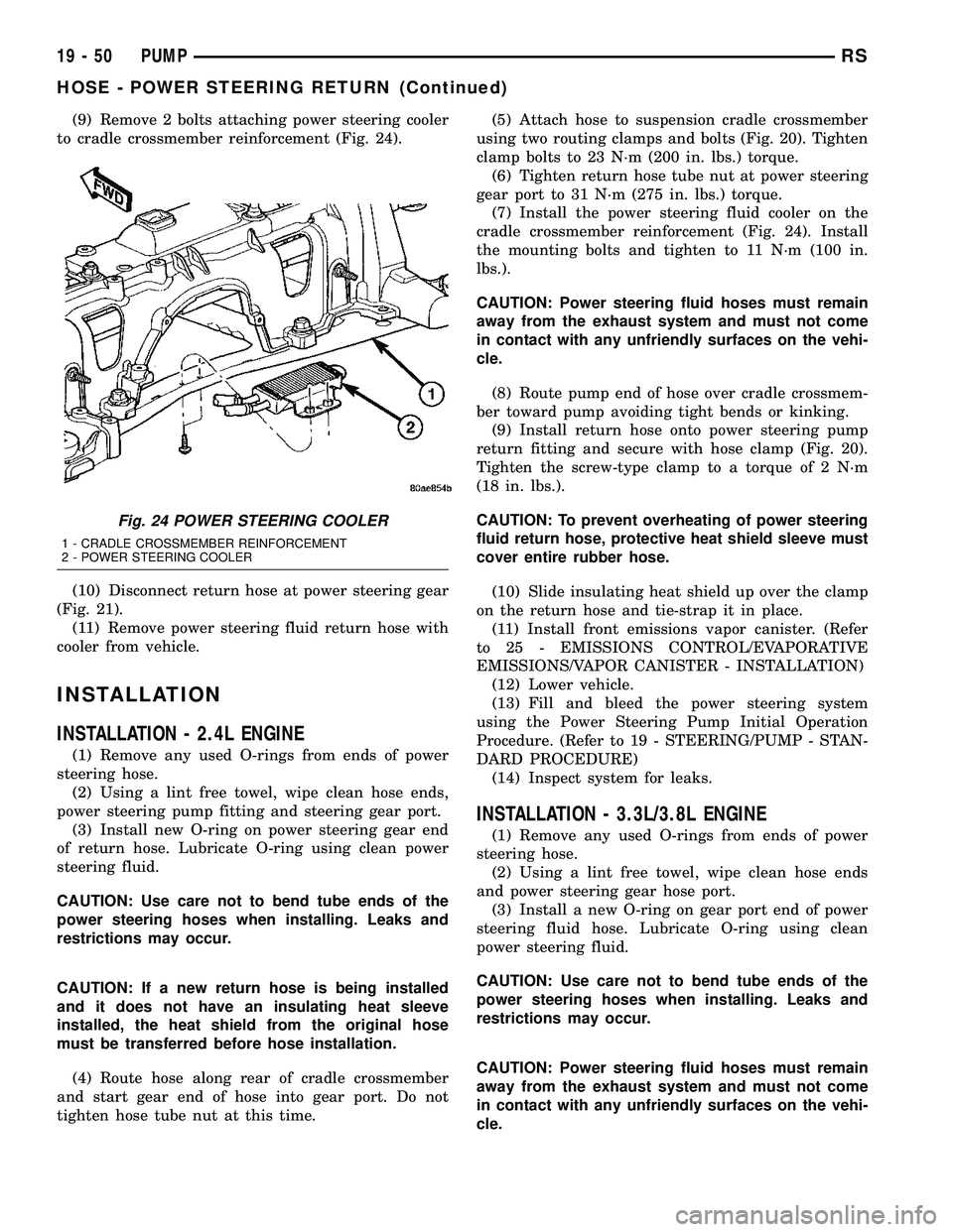
(9) Remove 2 bolts attaching power steering cooler
to cradle crossmember reinforcement (Fig. 24).
(10) Disconnect return hose at power steering gear
(Fig. 21).
(11) Remove power steering fluid return hose with
cooler from vehicle.
INSTALLATION
INSTALLATION - 2.4L ENGINE
(1) Remove any used O-rings from ends of power
steering hose.
(2) Using a lint free towel, wipe clean hose ends,
power steering pump fitting and steering gear port.
(3) Install new O-ring on power steering gear end
of return hose. Lubricate O-ring using clean power
steering fluid.
CAUTION: Use care not to bend tube ends of the
power steering hoses when installing. Leaks and
restrictions may occur.
CAUTION: If a new return hose is being installed
and it does not have an insulating heat sleeve
installed, the heat shield from the original hose
must be transferred before hose installation.
(4) Route hose along rear of cradle crossmember
and start gear end of hose into gear port. Do not
tighten hose tube nut at this time.(5) Attach hose to suspension cradle crossmember
using two routing clamps and bolts (Fig. 20). Tighten
clamp bolts to 23 N´m (200 in. lbs.) torque.
(6) Tighten return hose tube nut at power steering
gear port to 31 N´m (275 in. lbs.) torque.
(7) Install the power steering fluid cooler on the
cradle crossmember reinforcement (Fig. 24). Install
the mounting bolts and tighten to 11 N´m (100 in.
lbs.).
CAUTION: Power steering fluid hoses must remain
away from the exhaust system and must not come
in contact with any unfriendly surfaces on the vehi-
cle.
(8) Route pump end of hose over cradle crossmem-
ber toward pump avoiding tight bends or kinking.
(9) Install return hose onto power steering pump
return fitting and secure with hose clamp (Fig. 20).
Tighten the screw-type clamp to a torque of 2 N´m
(18 in. lbs.).
CAUTION: To prevent overheating of power steering
fluid return hose, protective heat shield sleeve must
cover entire rubber hose.
(10) Slide insulating heat shield up over the clamp
on the return hose and tie-strap it in place.
(11) Install front emissions vapor canister. (Refer
to 25 - EMISSIONS CONTROL/EVAPORATIVE
EMISSIONS/VAPOR CANISTER - INSTALLATION)
(12) Lower vehicle.
(13) Fill and bleed the power steering system
using the Power Steering Pump Initial Operation
Procedure. (Refer to 19 - STEERING/PUMP - STAN-
DARD PROCEDURE)
(14) Inspect system for leaks.
INSTALLATION - 3.3L/3.8L ENGINE
(1) Remove any used O-rings from ends of power
steering hose.
(2) Using a lint free towel, wipe clean hose ends
and power steering gear hose port.
(3) Install a new O-ring on gear port end of power
steering fluid hose. Lubricate O-ring using clean
power steering fluid.
CAUTION: Use care not to bend tube ends of the
power steering hoses when installing. Leaks and
restrictions may occur.
CAUTION: Power steering fluid hoses must remain
away from the exhaust system and must not come
in contact with any unfriendly surfaces on the vehi-
cle.
Fig. 24 POWER STEERING COOLER
1 - CRADLE CROSSMEMBER REINFORCEMENT
2 - POWER STEERING COOLER
19 - 50 PUMPRS
HOSE - POWER STEERING RETURN (Continued)
Page 1458 of 2339
(4) Route hose (with cooler attached) up toward
reservoir avoiding tight bends or kinking.
(5) Start steering gear end of hose into gear port.
Do not tighten hose tube nut at this time.
(6) Attach return hose tubes to suspension cradle
crossmember using routing clamp and bolt (Fig. 21).
Tighten clamp bolt to 23 N´m (200 in. lbs.) torque.
(7) Install the power steering fluid cooler on the
cradle crossmember reinforcement (Fig. 24). Install
the mounting bolts and tighten to 11 N´m (100 in.
lbs.). When installing mounting bolts, include pres-
sure hose routing clamp.
(8) Tighten hose tube nut at power steering gear
port to 31 N´m (275 in. lbs.) torque.
(9) Install front emissions vapor canister. (Refer to
25 - EMISSIONS CONTROL/EVAPORATIVE EMIS-
SIONS/VAPOR CANISTER - INSTALLATION)
(10) Lower vehicle.
(11) Install return hose tube into retainer on ABS
bracket (Fig. 21). Close the bracket.
(12) Install return hose onto reservoir (Fig. 22).
Slide the hose clamp into position on fluid reservoir
and attach it.Be sure hose clamp in installed
past bead on fluid reservoir fitting.
(13) Fill and bleed power steering system using
the Power Steering Pump Initial Operation Proce-
dure. (Refer to 19 - STEERING/PUMP - STANDARD
PROCEDURE)
(14) Inspect system for leaks.
HOSE - POWER STEERING
SUPPLY
REMOVAL
REMOVAL - 2.4L ENGINE
(1) Remove filler cap from power steering fluid res-
ervoir.
(2) Using a siphon pump, remove as much power
steering fluid as possible from the power steering
fluid reservoir.
(3) Raise vehicle. (Refer to LUBRICATION &
MAINTENANCE/HOISTING - STANDARD PROCE-
DURE)
(4) Remove hose clamp securing supply hose to
power steering pump, then remove supply hose from
pump fitting.
(5) Lower vehicle.
(6) Remove hose clamp attaching power steering
fluid supply hose to power steering fluid reservoir,
then remove supply hose.
(7) Remove the power steering fluid supply hose
from the vehicle.
REMOVAL - 3.3L/3.8L ENGINE
NOTE: Before proceeding, review all WARNINGS
and CAUTIONS. (Refer to 19 - STEERING/PUMP -
WARNING)(Refer to 19 - STEERING/PUMP - CAU-
TION)
(1) Remove cap from power steering fluid reser-
voir.
(2) Using a siphon pump, remove as much power
steering fluid as possible from power steering fluid
reservoir.
(3) Place an oil drain pan under vehicle to catch
any draining power steering fluid.
(4) Remove clamp attaching supply hose to power
steering fluid reservoir. Disconnect hose from reser-
voir (Fig. 22).
(5) Pull upward on hose routing clip releasing it
from bracket on cylinder head cover (Fig. 22).
NOTE: It may be necessary to remove air cleaner
housing to gain greater access to supply hose at
power steering pump. (Refer to 9 - ENGINE/AIR
INTAKE SYSTEM/AIR CLEANER HOUSING -
REMOVAL)
(6) Remove clamp attaching supply hose to power
steering pump. Disconnect hose from pump and
remove from vehicle (Fig. 22).
INSTALLATION
INSTALLATION - 2.4L ENGINE
(1) Install and correctly route power steering fluid
supply hose from remote fluid reservoir to power
steering pump.
(2) Install fluid supply hose onto power steering
fluid reservoir. Install hose clamp.Be sure hose
clamp is installed past bead on fluid reservoir
fitting.
(3) Raise vehicle. (Refer to LUBRICATION &
MAINTENANCE/HOISTING - STANDARD PROCE-
DURE)
(4) Install power steering fluid supply hose on
power steering pump supply fitting. Install hose
clamp.Be sure hose clamp is installed past bead
on pump fitting.
(5) Lower vehicle.
(6) Fill and bleed power steering system using
Power Steering Pump Initial Operation Procedure.
(Refer to 19 - STEERING/PUMP - STANDARD PRO-
CEDURE)
(7) Inspect system for leaks.
RSPUMP19-51
HOSE - POWER STEERING RETURN (Continued)
Page 1836 of 2339
(2) Insert ends of crossmember between layered
metal sections of radiator closure panel at each side
of radiator.
(3) Align with paint breaks around bolt heads.
(4) Install bolts attaching ends of crossmember to
radiator closure panel (Fig. 16). Tighten bolts to 19
N´m (14 ft. lbs.) torque.
(5) Install bolts attaching radiator isolators to
crossmember.
(6) Install screw attaching coolant recovery bottle
to crossmember.
(7) Install bolt attaching air cleaner housing to
crossmember.
(8) Install engine air inlet resonator.
(9) Install hood prop rod.
(10) Align hood latch by placing latch over net
pierce tabs. If alignment is required, flatten tabs.
(11) Install bolts attaching hood latch to cross-
member and clip cable. Tighten bolts to 13.5 N´m (10
ft. lbs.) torque.
(12) Install radiator sight shield.
(13) Verify hood latch operation and hood align-
ment.
FRONT WHEELHOUSE
SPLASH SHIELD
REMOVAL
(1) Hoist and support vehicle on safety stands.
(Refer to LUBRICATION & MAINTENANCE/HOIST-
ING - STANDARD PROCEDURE).
(2) Remove front wheel.
(3) Remove push pin fasteners attaching splash
shield to frame rail forward of suspension.
(4) Remove push pin fasteners attaching splash
shield to frame rail rearward of suspension.
(5) Remove screws attaching wheelhouse splash
shield to front fender and front bumper fascia.
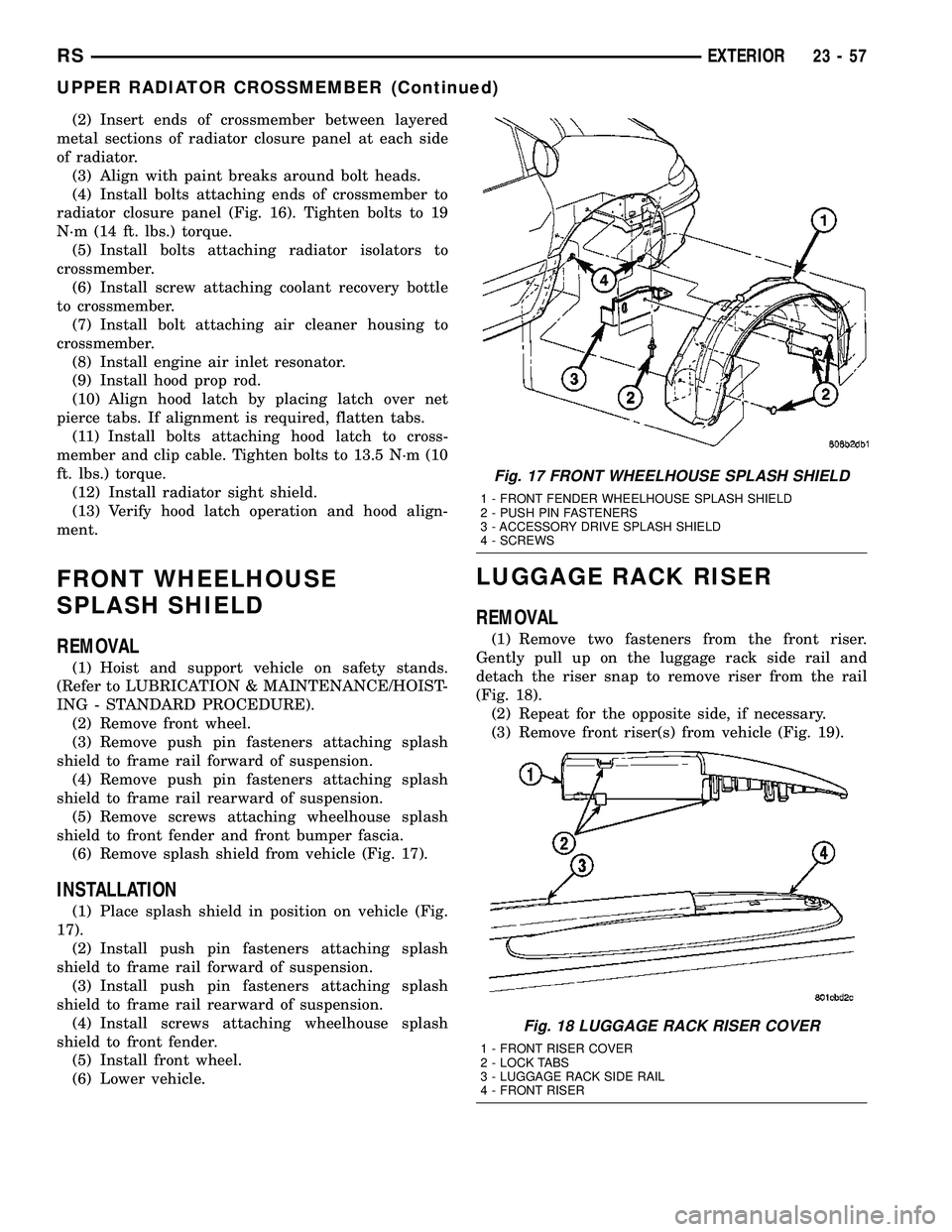
(6) Remove splash shield from vehicle (Fig. 17).
INSTALLATION
(1) Place splash shield in position on vehicle (Fig.
17).
(2) Install push pin fasteners attaching splash
shield to frame rail forward of suspension.
(3) Install push pin fasteners attaching splash
shield to frame rail rearward of suspension.
(4) Install screws attaching wheelhouse splash
shield to front fender.
(5) Install front wheel.
(6) Lower vehicle.
LUGGAGE RACK RISER
REMOVAL
(1) Remove two fasteners from the front riser.
Gently pull up on the luggage rack side rail and
detach the riser snap to remove riser from the rail
(Fig. 18).
(2) Repeat for the opposite side, if necessary.
(3) Remove front riser(s) from vehicle (Fig. 19).
Fig. 17 FRONT WHEELHOUSE SPLASH SHIELD
1 - FRONT FENDER WHEELHOUSE SPLASH SHIELD
2 - PUSH PIN FASTENERS
3 - ACCESSORY DRIVE SPLASH SHIELD
4 - SCREWS
Fig. 18 LUGGAGE RACK RISER COVER
1 - FRONT RISER COVER
2 - LOCK TABS
3 - LUGGAGE RACK SIDE RAIL
4 - FRONT RISER
RSEXTERIOR23-57
UPPER RADIATOR CROSSMEMBER (Continued)
Page 1997 of 2339
STRUCTURAL ADHESIVE
LOCATIONS
SPECIFICATIONS
SPECIFICATIONS - STRUCTURAL ADHESIVE
LOCATIONS
INDEX
DESCRIPTION FIGURE
UPPER COWL PLENUM, UPPER AND LOWER DASH PANEL 65
ROOF AND REAR QUARTER PANELS - LONG WHEEL BASE ONLY 66
FLOOR PAN - LONG WHEEL BASE ONLY 67
SUSPENSION HANGER REINFORCEMENTS - LONG WHEEL BASE ONLY 68
FRONT HINGE PILLAR REINFORCEMENTS - LONG WHEEL BASE ONLY 69
ROOF AND REAR QUARTER PANELS - SHORT WHEEL BASE ONLY 70
FLOOR PAN - SHORT WHEEL BASE ONLY 71
FRONT SIDE RAILS/OUTER CROSS MEMBER BRACKETS 72
OUTER ROOF PANEL/UPPER WINDSHIELD FRAME 73
COWL SIDE PANEL / BODY SIDE APERTURE, B-PILLAR / SLIDING DOOR TRACK
SUPPORT74
FRONT HINGE PILLAR REINFORCEMENT / COWL SIDE TAPPING PLATE 75
UPPER COWL PLENUM / UPPER AND LOWER DASH PANEL - RIGHT HAND DRIVE
ONLY76
23 - 218 BODY STRUCTURERS
Page 2001 of 2339
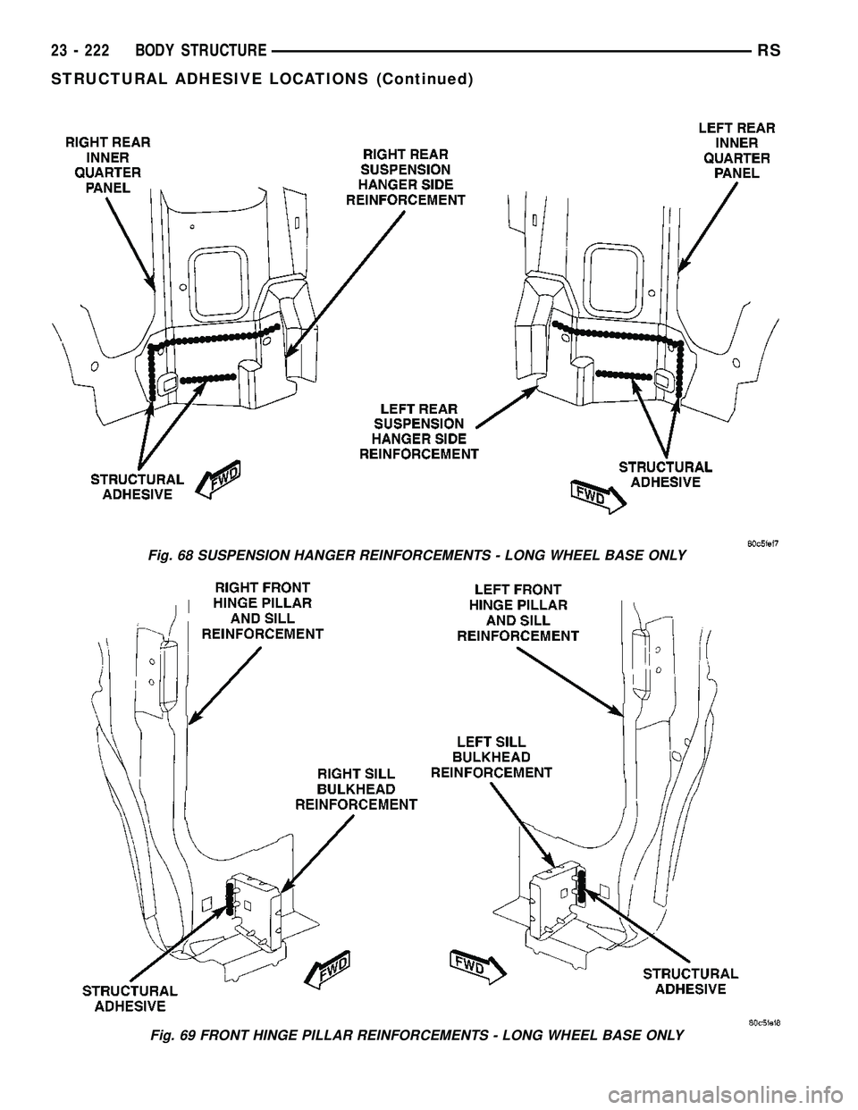
Fig. 68 SUSPENSION HANGER REINFORCEMENTS - LONG WHEEL BASE ONLY
Fig. 69 FRONT HINGE PILLAR REINFORCEMENTS - LONG WHEEL BASE ONLY
23 - 222 BODY STRUCTURERS
STRUCTURAL ADHESIVE LOCATIONS (Continued)
Page 2013 of 2339
WELD LOCATIONS
SPECIFICATIONS
SPECIFICATIONS - WELD LOCATIONS
INDEX
DESCRIPTION FIGURE
FRONT FENDER SHIELD - RIGHT 85
FRONT FENDER SHIELD - LEFT 86
STRUT TOWER AND REINFORCEMENTS - RIGHT 87
SUSPENSION RETAINERS AND REINFORCEMENTS - RIGHT 88
STRUT TOWER AND REINFORCEMENTS - LEFT 89
SUSPENSION RETAINERS AND REINFORCEMENTS - LEFT 90
FLOOR PAN REINFORCEMENTS - SIDE RAILS 91
REAR SUSPENSION BRACKETS 92
FLOOR PAN CROSS MEMBERS 93
SEAT REINFORCEMENTS - LONG WHEEL BASE ONLY 94
STRIKER REINFORCEMENTS - LONG WHEEL BASE ONLY 95
FUEL TANK MOUNTING/REAR SEAT AND SUSPENSION 96
REAR SUSPENSION HANGER BRACKETS - LONG WHEEL BASE 97
FRONT SEAT CROSS MEMBER 98
FLOOR PAN SIDE RAIL REINFORCEMENT 99
SILL BULKHEAD REINFORCEMENTS 100
FLOOR PAN CROSS MEMBER REINFORCEMENTS 101
FRONT SEAT CROSS MEMBER 102
SEAT REINFORCEMENT CROSS MEMBERS - SHORT WHEEL BASE 103
CENTER CONSOLE REINFORCEMENT - SHORT WHEEL BASE 104
REAR SUSPENSION HANGER BRACKETS - SHORT WHEEL BASE 105
LOWER LIFTGATE PANEL LATCH REINFORCEMENT 106
ENGINE MOUNTING PLATE AND TOW BRACKET 107
HEADLAMP MOUNTING PLATE 108
LOWER RADIATOR CROSS MEMBER BRACKETS 109
CROSS MEMBER EXTENSIONS 110
JACK MOUNTING BRACKET - LONG WHEEL BASE SHOWN, SHORT SIMILAR 111
FRONT SEAT CROSS MEMBER - LONG WHEELBASE ONLY 112
FRONT SEAT CROSS MEMBER - ALL WHEEL DRIVE ONLY 113
FUEL TANK SUPPORT CROSS MEMBERS - LONG WHEEL BASE ONLY 114
REAR SUPPORT AND TIRE STOWAGE CROSS MEMBERS - LONG WHEEL BASE
ONLY11 5
INNER SIDE SILLS - LONG WHEEL BASE ONLY 116
WHEELHOUSES, SIDE SILLS, SUSPENSION BRACKETS - LONG WHEEL BASE ONLY 117
REAR SEAT REINFORCEMENTS - SHORT WHEEL BASE ONLY 118
23 - 234 BODY STRUCTURERS