2005 CHRYSLER CARAVAN service
[x] Cancel search: servicePage 281 of 2339

PARK ASSIST SYSTEM
The Park Assist System display activates an audi-
ble tone that changes from intermittent to continu-
ous as the final two Light Emitting Diodes (LED's)
are illuminated on one side or both sides of the dis-
play.
The system detection length from the rear of the
vehicle is 0.3 meters to 1.5 meters. This area extends
around the rear side of the vehicle. The system detec-
tion height from the ground is 0.2 meters to about
1.5 meters. The radio mutes when the system acti-
vates its audible tone.
When the driver selects Reverse the system scans
for objects behind the vehicle using four sensors
located in the rear bumper. A warning display above
the rear window provides both visible and audible
warnings indicating the range of the object.
The system is active only when the transmission
gear selector is in reverse for vehicle speeds less than
16 Km/h (10 mph). If the vehicle's Parking/Emer-
gency Brake is applied, the system is deactivated.
The display contains two sets of yellow and red
Light Emitting Diode's (LED's) that the driver can
see as they look over their shoulder while backing
up. Each side of the vehicle has its own warning
LED's. The system provides a visual warning by illu-
minating one or more yellow LED's as the vehicle
gets closer to the object. As the vehicle continues to
approach the object, one red LED is illuminated and
the system emits a series of short beeps. The tone
will remain constant and both red LED's are illumi-
nated once the vehicle is within 12 inches (30.5 cm)
of the object.
The system can be turned ON or OFF through the
Electronic Vehicle Information Center (EVIC) when
the vehicle is in PARK. If the park assist system is
turned OFF, a single chime will sound and the EVIC
will display the following message ªREAR PARK
ASSIST OFFº, when the vehicle is in reverse.
²Ensure that the rear bumper is free of dirt and
debris to keep the system operating properly.
²Jackhammers, large trucks, and other vibrations
could affect the performance of the system.
²Ensure that the parking brake is not applied.
If ªService Park Assist Systemº appears in the
EVIC after making sure the rear bumper is clean,
proceed to diagnose the system using a scan tool and
the appropriate diagnostic information.
WARNING
On vehicles equipped with airbags, disable
the airbag system before attempting any steer-
ing wheel, steering column, or instrument
panel component diagnosis or service. Discon-
nect and isolate the battery negative (ground)
cable, then wait two minutes for the airbag sys-
tem capacitor to discharge before performing
further diagnosis or service. This is the only
sure way to disable the airbag system. Failure
to take the proper precautions could result in
accidental airbag deployment, personal injury,
or death.
DIAGNOSIS AND TESTING - CHIME SYSTEM
Refer to the proper Body Diagnostic Procedures
manual for complete Diagnosis and Testing of the
Chime System.
NO TONE WHEN IGNITION SWITCH IS TURNED ON
AND DRIVER'S SEAT BELT IS NOT BUCKLED.
(1) Using a DRB llltscan tool, actuate chime
(BCM actuates).
(2) Using a voltmeter, check for voltage:
(a) BCM has two battery feeds at pin 1 and pin
5 of the 6±way connector.
(b) Pin 5 of the (BX2) 32 way connector of the
BCM for ignition feed.
(c) Check voltage (PX2) connector, pin 34 for 12v.
(d) If voltage OK, go to step Step 3
(e) If NO voltage repair as necessary. Refer to
the appropriate wiring information. The wiring
information includes wiring diagrams, proper wire
and connector repair procedures, further details on
wire harness routing and retention, as well as pin-
out and location views for the various wire harness
connectors, splices and grounds.
(3) Check drivers seat belt buckle switch input
(from Occupant Restraint Controller (ORC) for a
closed circuit when not buckled. If input not seen,
look for open in wiring or switch. The switch is
grounded when belt is not buckled.
(4) Verify Programmable Communication Interface
(PCI) data bus communication between ORC and
BCM.
8B - 2 CHIME/BUZZERRS
CHIME/BUZZER (Continued)
Page 284 of 2339

²System diagnostics - diagnosis and error han-
dling (sensors, display, module).
²Data exchange over the Programmable Commu-
nication Interface (PCI) data bus.
OPERATION
The module has a number of functions:
²Supply voltage to the sensors and display.
²Disconnection of the display with bus idle and
over voltage Vmax.
²Triggering the sensors.
²Analyze echo delay times and calculate obstacle
distances.
²Bi-directional data communication to the display
for diagnosis.
²System diagnostics - diagnosis and error han-
dling (sensors, display, module).
²Data exchange over the Programmable Commu-
nication Interface (PCI) data bus.
The system detection length from the rear of the
vehicle is 0.3 meters to 1.5 meters. This area extends
around the rear side of the vehicle. The system detec-
tion height from the ground is 0.2 meters to about
1.5 meters. The radio mutes when the system acti-
vates its audible tone.When the driver selects Reverse, the system scans
for objects behind the vehicle using four sensors
located in the rear bumper. Objects can be detected
from up to 1.5 meters. A warning display above the
rear window provides both visible and audible warn-
ings indicating the range of the object.
The system is active only when the vehicle is in
reverse for vehicle speeds less than 16 Km/h (10
mph). If the vehicles Parking/Emergency Brake is
applied, the system is deactivated.
The display contains two sets of yellow and red
Light Emitting Diode's (LED's) that the driver can
see as they look over their shoulder while backing
up. Each side of the vehicle has its own warning
LED's. The system provides a visual warning by illu-
minating one or more yellow LED's as the vehicle
gets closer to the object. As the vehicle continues to
approaches the object, one red LED is illuminated
and the system emits a series of short beeps. The
tone will remain constant and both red LED's are
illuminated once the vehicle is within 12 inches (30.5
cm) of the object.
The system can be turned ON or OFF through the
Electronic Vehicle Information Center (EVIC) when
the vehicle is in PARK. If the park assist system is
turned OFF, a single chime will sound and the EVIC
will display the following message ªREAR PARK
ASSIST OFFº, when the vehicle is in reverse.
²Ensure that the rear bumper is free of dirt and
debris to keep the system operating properly.
²Jackhammers, large trucks, and other vibrations
could affect the performance of the system.
²Ensure that the parking brake is not applied.
If ªService Park Assist Systemº appears in the
EVIC after making sure the rear bumper is clean,
proceed to diagnose the system using a scan tool and
the appropriate diagnostic information.
To diagnose the Park Assist Module, use a scan
tool and the appropriate body diagnostic information.
REMOVAL
(1) Open hood.
(2)
Disconnect and isolate the battery negative cable.
(3) Remove the left quarter trim panel (Refer to 23
- BODY/INTERIOR/QUARTER TRIM PANEL -
REMOVAL).
Fig. 3 PARK ASSIST MODULE - LOCATION
1 - RETAINING SCREW J-CLIPS
2 - LEFT QUARTER PANEL/C-PILLAR
3 - MODULE RETAINING SCREWS
4 - PARK ASSIST MODULE
RSCHIME/BUZZER8B-5
PARK ASSIST MODULE (Continued)
Page 285 of 2339

(4) Disconnect the Park Assist Module electrical
connector (Fig. 4).
(5) Remove the two attaching screws and separate
the module from vehicle (Fig. 3).
INSTALLATION
(1) Position the Park Assist Module and install the
two attaching screws (Fig. 3). Torque screws to 3.5
N´m (30 in. lbs.).
(2) Connect the Park Assist Module electrical con-
nector (Fig. 4).
(3) Install the left quarter trim panel (Refer to 23 -
BODY/INTERIOR/QUARTER TRIM PANEL -
INSTALLATION).
(4) Connect the battery negative cable.
(5) Close hood.
(6) Verify vehicle and system operation.
PARK ASSIST SENSOR
DESCRIPTION
The Park Assist Sensors are located in the rear
bumper fascia mounted equally apart (Fig. 5). The
sensors generate ultrasonic pulses when triggered by
the park assist module when an obstacle is detected.
The sensors then signal the module when reflected
ultrasonic pulses are received.
The sensors detect objects with an ultrasonic pulse
that reflects off the object and then is sent to the
module to determine the distance of the object.
OPERATION
The Park Assist Sensors:
²Generate ultrasonic pulses when triggered by
the Park Assist Module.
²Reception/filtering of ultrasonic energy received.
²Signalling the module of received ultrasonic
pulses that meet threshold criteria.
The sensors are supplied power by the module. The
sensor supply is enabled when the sensor function is
necessary.
The sensors detection length from the rear of the
vehicle is 0.3 meters to 1.5 meters. This area extends
around the rear side of the vehicle. The sensor detec-
tion height from the ground is 0.2 meters to about
1.5 meters.
²Ensure that the rear bumper (sensors) is free of
dirt and debris to keep the system operating prop-
erly.
²Jackhammers, large trucks, and other vibrations
could affect the performance of the system.
²Ensure that the parking brake is not applied.
If ªService Park Assist Systemº appears in the
EVIC after making sure the rear bumper is clean,
proceed to diagnose the system using a scan tool and
the appropriate diagnostic information.
REMOVAL
(1) Open hood.
(2) Disconnect and isolate the battery negative
cable.
(3) Remove rear fascia (Refer to 13 - FRAME &
BUMPERS/BUMPERS/REAR FASCIA - REMOVAL).
(4) Unsnap Park Assist Sensor from the retaining
housing and remove from fascia.
INSTALLATION
(1)Position the Park Assist Sensor over the retain-
ing housing and firmly snap into housing in rear fascia.
(2) Install the rear fascia (Refer to 13 - FRAME &
BUMPERS/BUMPERS/REAR FASCIA - INSTALLA-
TION).
(3) Connect the battery negative cable.
(4) Close hood.
(5) Verify vehicle and system operation.
Fig. 4 PARK ASSIST MODULE ELECTRICAL
CONNECTOR
1 - MODULE ELECTRICAL CONNECTOR
2 - PARK ASSIST MODULE
Fig. 5 PARK ASSIST SENSOR LOCATION
8B - 6 CHIME/BUZZERRS
PARK ASSIST MODULE (Continued)
Page 303 of 2339

SLIDING DOOR CONTROL
MODULE
DESCRIPTION
Vehicles equipped with a power sliding door system
utilize a sliding door control module. The sliding door
control module is located behind the sliding door trim
panel in the center of the door, just above the sliding
door motor (Fig. 15). This module controls the opera-
tion of the door through the Programmable Commu-
nication Interface (PCI) data bus circuit and the
Body Control Module (BCM). The sliding door control
module contains software technology which enables it
to detect resistance to door travel and to reverse door
travel in order to avoid damage to the door or to
avoid possible personal injury if the obstruction is a
person. This feature functions in both the opening
and closing cycles. If the power sliding door system
develops any problems the control module will store
and recall Diagnostic Trouble Codes (DTC). The use
of a diagnostic scan tool, such as the DRB IIItis
required to read and troubleshoot these trouble
codes. The sliding door control module can be
reflashed if necessary. Refer to the latest Technical
Service Bulletin (TSB) Information for any updates.The power door control module is a replaceable
component and cannot be repaired, if found to be
faulty it must be replaced.
OPERATION
The power sliding door control module serves as
the main computer for the power sliding door system.
All power door functions are processed through the
power sliding door control module and/or the vehicles
Body Control Module (BCM). At the start of a power
open command, a signal is sent to the BCM and then
to the power sliding door control module via the Pro-
grammable Communication Interface (PCI) data bus
circuit. This signal, generated by any of the power
door command switches, tells the power sliding door
control module to activate a power latch release,
engage the clutch assembly and drive the door into
the full open position. If an obstacle is felt during
this power open cycle, the module will reverse direc-
tion and close the door. This process is also enabled
during a power close cycle. This process will repeat
three times, and if a fourth obstacle is detected, the
door will go into full manual mode. Once the full
open position is obtained, a hold open latch assembly
mounted full open switch tells the power sliding door
control module that the door has reached the full
open position. If the power sliding door system devel-
ops any problems the power sliding door control mod-
ule will store and recall Diagnostic Trouble Codes
(DTC). The use of a diagnostic scan tool, such as the
DRB IIItis required to read and troubleshoot these
trouble codes.
DIAGNOSIS AND TESTING
SLIDING DOOR CONTROL MODULE
Any diagnosis of the power sliding door sys-
tem should begin with the use of the DRB IIIt
diagnostic tool. For information on the use of
the DRB IIIt, refer to the appropriate Diagnos-
tic Procedures information.
Inspect the related wiring harness connectors for
broken, bent, pushed out, or corroded terminals.
Refer to the appropriate wiring information.
REMOVAL
(1) Disconnect and isolate the battery negative
cable.
(2) Remove the appropriate door trim panel from
the vehicle. (Refer to 23 - BODY/DOORS - SLIDING/
TRIM PANEL - REMOVAL)
(3) Remove the weather shield.
Fig. 15 Power Side Door Components
1 - SLIDING DOOR CONTROL MODULE
2 - MODULE RETAINING SCREW
3 - MODULE ELECTRICAL CONNECTORS
4 - DOOR MOTOR ASSEMBLY
5 - FLEX DRIVE ASSEMBLY
6 - DOOR MOTOR RETAINING FASTENERS
7 - DOOR MOTOR ELECTRICAL CONNECTOR
8E - 18 ELECTRONIC CONTROL MODULESRS
Page 307 of 2339

OPERATION
The battery system is designed to provide a safe,
efficient, reliable and mobile means of delivering and
storing electrical energy. This electrical energy is
required to operate the engine starting system, as
well as to operate many of the other vehicle acces-
sory systems for limited durations while the engine
and/or the charging system are not operating. The
battery system is also designed to provide a reserve
of electrical energy to supplement the charging sys-
tem for short durations while the engine is running
and the electrical current demands of the vehicle
exceed the output of the charging system. In addition
to delivering, and storing electrical energy for the
vehicle, the battery system serves as a capacitor and
voltage stabilizer for the vehicle electrical system. It
absorbs most abnormal or transient voltages caused
by the switching of any of the electrical components
or circuits in the vehicle.
DIAGNOSIS AND TESTING
BATTERY SYSTEM
The battery, starting, and charging systems in the
vehicle operate with one another and must be tested
as a complete system. In order for the engine to start
and the battery to maintain its charge properly, all of
the components that are used in these systems must
perform within specifications. It is important that
the battery, starting, and charging systems be thor-
oughly tested and inspected any time a battery needs
to be charged or replaced. The cause of abnormal bat-
tery discharge, overcharging or early battery failuremust be diagnosed and corrected before a battery is
replaced and before a vehicle is returned to service.
The service information for these systems has been
separated within this service manual to make it eas-
ier to locate the specific information you are seeking.
However, when attempting to diagnose any of these
systems, it is important that you keep their interde-
pendency in mind.
The diagnostic procedures used for the battery,
starting, and charging systems include the most
basic conventional diagnostic methods, to the more
sophisticated On-Board Diagnostics (OBD) built into
the Powertrain Control Module (PCM). Use of an
induction-type milliampere ammeter, a volt/ohmme-
ter, a battery charger, a carbon pile rheostat (load
tester) and a 12-volt test lamp may be required. All
OBD-sensed systems are monitored by the PCM.
Each monitored circuit is assigned a Diagnostic Trou-
ble Code (DTC). The PCM will store a DTC in elec-
tronic memory for any failure it detects. (Refer to 8 -
ELECTRICAL/CHARGING - DIAGNOSIS AND
TESTING) for the proper charging system on-board
diagnostic test procedures.MICRO 420 BATTERY TESTER
The Micro 420 automotive battery tester is
designed to help the dealership technicians diagnose
the cause of a defective battery. Follow the instruc-
tion manual supplied with the tester to properly
diagnose a vehicle. If the instruction manual is not
available refer to the standard procedure in this sec-
tion, which includes the directions for using the
Micro 420 battery tester.
8F - 2 BATTERY SYSTEMRS
BATTERY SYSTEM (Continued)
Page 310 of 2339

CLEANING
The following information details the recommended
cleaning procedures for the battery and related com-
ponents. In addition to the maintenance schedules
found in this service manual and the owner's man-
ual, it is recommended that these procedures be per-
formed any time the battery or related components
must be removed for vehicle service.
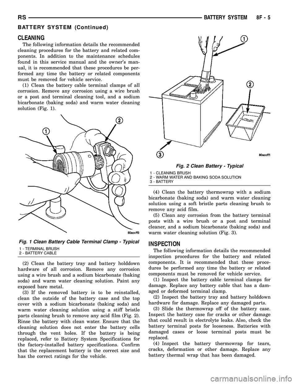
(1) Clean the battery cable terminal clamps of all
corrosion. Remove any corrosion using a wire brush
or a post and terminal cleaning tool, and a sodium
bicarbonate (baking soda) and warm water cleaning
solution (Fig. 1).
(2) Clean the battery tray and battery holddown
hardware of all corrosion. Remove any corrosion
using a wire brush and a sodium bicarbonate (baking
soda) and warm water cleaning solution. Paint any
exposed bare metal.
(3) If the removed battery is to be reinstalled,
clean the outside of the battery case and the top
cover with a sodium bicarbonate (baking soda) and
warm water cleaning solution using a stiff bristle
parts cleaning brush to remove any acid film (Fig. 2).
Rinse the battery with clean water. Ensure that the
cleaning solution does not enter the battery cells
through the vent holes. If the battery is being
replaced, refer to Battery System Specifications for
the factory-installed battery specifications. Confirm
that the replacement battery is the correct size and
has the correct ratings for the vehicle.(4) Clean the battery thermowrap with a sodium
bicarbonate (baking soda) and warm water cleaning
solution using a soft bristle parts cleaning brush to
remove any acid film.
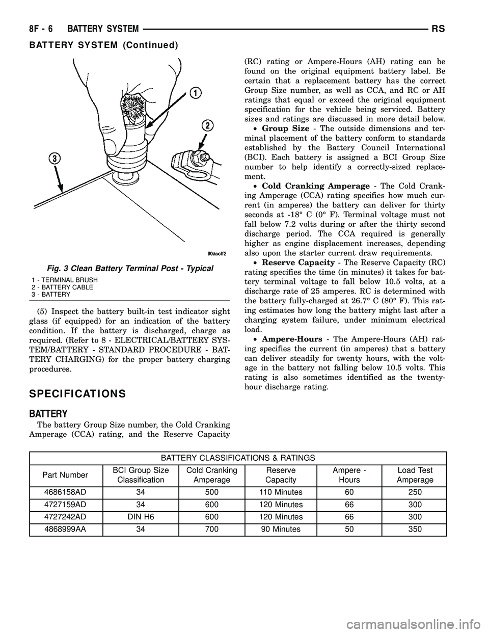
(5) Clean any corrosion from the battery terminal
posts with a wire brush or a post and terminal
cleaner, and a sodium bicarbonate (baking soda) and
warm water cleaning solution (Fig. 3).
INSPECTION
The following information details the recommended
inspection procedures for the battery and related
components. It is recommended that these proce-
dures be performed any time the battery or related
components must be removed for vehicle service.
(1) Inspect the battery cable terminal clamps for
damage. Replace any battery cable that has a dam-
aged or deformed terminal clamp.
(2) Inspect the battery tray and battery holddown
hardware for damage. Replace any damaged parts.
(3) Slide the thermowrap off of the battery case.
Inspect the battery case for cracks or other damage
that could result in electrolyte leaks. Also, check the
battery terminal posts for looseness. Batteries with
damaged cases or loose terminal posts must be
replaced.
(4) Inspect the battery thermowrap for tears,
cracks, deformation or other damage. Replace any
battery thermal wrap that has been damaged.
Fig. 1 Clean Battery Cable Terminal Clamp - Typical
1 - TERMINAL BRUSH
2 - BATTERY CABLE
Fig. 2 Clean Battery - Typical
1 - CLEANING BRUSH
2 - WARM WATER AND BAKING SODA SOLUTION
3 - BATTERY
RSBATTERY SYSTEM8F-5
BATTERY SYSTEM (Continued)
Page 311 of 2339

(5) Inspect the battery built-in test indicator sight
glass (if equipped) for an indication of the battery
condition. If the battery is discharged, charge as
required. (Refer to 8 - ELECTRICAL/BATTERY SYS-
TEM/BATTERY - STANDARD PROCEDURE - BAT-
TERY CHARGING) for the proper battery charging
procedures.
SPECIFICATIONS
BATTERY
The battery Group Size number, the Cold Cranking
Amperage (CCA) rating, and the Reserve Capacity(RC) rating or Ampere-Hours (AH) rating can be
found on the original equipment battery label. Be
certain that a replacement battery has the correct
Group Size number, as well as CCA, and RC or AH
ratings that equal or exceed the original equipment
specification for the vehicle being serviced. Battery
sizes and ratings are discussed in more detail below.
²Group Size- The outside dimensions and ter-
minal placement of the battery conform to standards
established by the Battery Council International
(BCI). Each battery is assigned a BCI Group Size
number to help identify a correctly-sized replace-
ment.
²Cold Cranking Amperage- The Cold Crank-
ing Amperage (CCA) rating specifies how much cur-
rent (in amperes) the battery can deliver for thirty
seconds at -18É C (0É F). Terminal voltage must not
fall below 7.2 volts during or after the thirty second
discharge period. The CCA required is generally
higher as engine displacement increases, depending
also upon the starter current draw requirements.
²Reserve Capacity- The Reserve Capacity (RC)
rating specifies the time (in minutes) it takes for bat-
tery terminal voltage to fall below 10.5 volts, at a
discharge rate of 25 amperes. RC is determined with
the battery fully-charged at 26.7É C (80É F). This rat-
ing estimates how long the battery might last after a
charging system failure, under minimum electrical
load.
²Ampere-Hours- The Ampere-Hours (AH) rat-
ing specifies the current (in amperes) that a battery
can deliver steadily for twenty hours, with the volt-
age in the battery not falling below 10.5 volts. This
rating is also sometimes identified as the twenty-
hour discharge rating.
BATTERY CLASSIFICATIONS & RATINGS
Part NumberBCI Group Size
ClassificationCold Cranking
AmperageReserve
CapacityAmpere -
HoursLoad Test
Amperage
4686158AD 34 500 110 Minutes 60 250
4727159AD 34 600 120 Minutes 66 300
4727242AD DIN H6 600 120 Minutes 66 300
4868999AA 34 700 90 Minutes 50 350
Fig. 3 Clean Battery Terminal Post - Typical
1 - TERMINAL BRUSH
2 - BATTERY CABLE
3 - BATTERY
8F - 6 BATTERY SYSTEMRS
BATTERY SYSTEM (Continued)
Page 312 of 2339

SPECIAL TOOLS
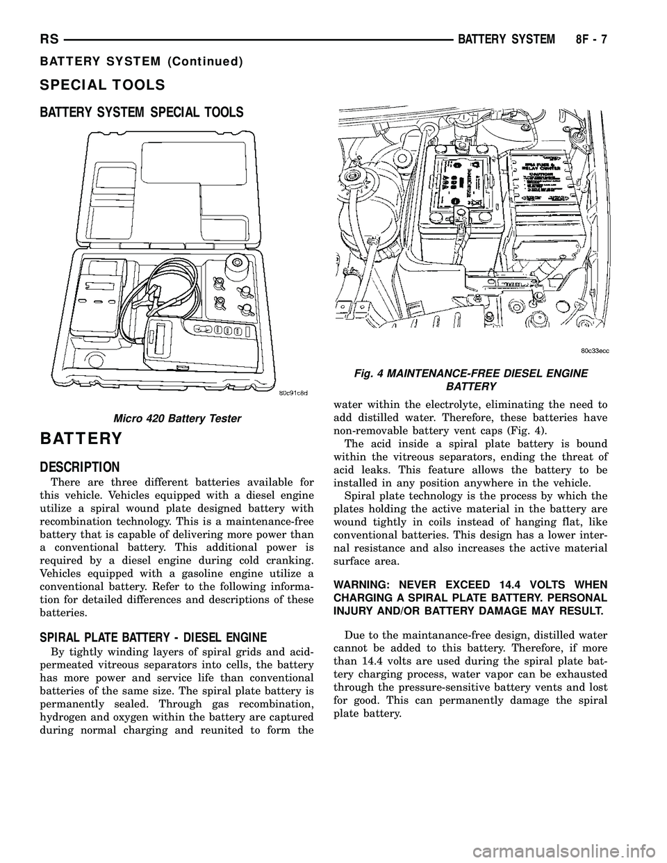
BATTERY SYSTEM SPECIAL TOOLS
BATTERY
DESCRIPTION
There are three different batteries available for
this vehicle. Vehicles equipped with a diesel engine
utilize a spiral wound plate designed battery with
recombination technology. This is a maintenance-free
battery that is capable of delivering more power than
a conventional battery. This additional power is
required by a diesel engine during cold cranking.
Vehicles equipped with a gasoline engine utilize a
conventional battery. Refer to the following informa-
tion for detailed differences and descriptions of these
batteries.
SPIRAL PLATE BATTERY - DIESEL ENGINE
By tightly winding layers of spiral grids and acid-
permeated vitreous separators into cells, the battery
has more power and service life than conventional
batteries of the same size. The spiral plate battery is
permanently sealed. Through gas recombination,
hydrogen and oxygen within the battery are captured
during normal charging and reunited to form thewater within the electrolyte, eliminating the need to
add distilled water. Therefore, these batteries have
non-removable battery vent caps (Fig. 4).
The acid inside a spiral plate battery is bound
within the vitreous separators, ending the threat of
acid leaks. This feature allows the battery to be
installed in any position anywhere in the vehicle.
Spiral plate technology is the process by which the
plates holding the active material in the battery are
wound tightly in coils instead of hanging flat, like
conventional batteries. This design has a lower inter-
nal resistance and also increases the active material
surface area.
WARNING: NEVER EXCEED 14.4 VOLTS WHEN
CHARGING A SPIRAL PLATE BATTERY. PERSONAL
INJURY AND/OR BATTERY DAMAGE MAY RESULT.
Due to the maintanance-free design, distilled water
cannot be added to this battery. Therefore, if more
than 14.4 volts are used during the spiral plate bat-
tery charging process, water vapor can be exhausted
through the pressure-sensitive battery vents and lost
for good. This can permanently damage the spiral
plate battery.
Micro 420 Battery Tester
Fig. 4 MAINTENANCE-FREE DIESEL ENGINE
BATTERY
RSBATTERY SYSTEM8F-7
BATTERY SYSTEM (Continued)