2005 CHRYSLER CARAVAN integrated power module
[x] Cancel search: integrated power modulePage 1591 of 2339

TRANSMISSION CONTROL
RELAY
DESCRIPTION
The transmission control relay (Fig. 306) is located
in the Intelligent Power Module (IPM), which is
located on the left side of the engine compartment
between the battery and left fender.
OPERATION
The relay is supplied fused B+ voltage, energized by
the PCM/TCM, and is used to supply power to the sole-
noid pack when the transmission is in normal operating
mode. When the relay is ªoffº, no power is supplied to
the solenoid pack and the transmission is in ªlimp-inº
mode. After a controller reset (ignition key turned to the
ªrunº position or after cranking engine), the PCM/TCM
energizes the relay. Prior to this, the PCM/TCM verifies
that the contacts are open by checking for no voltage at
the switched battery terminals. After this is verified,
the voltage at the solenoid pack pressure switches is
checked. After the relay is energized, the PCM/TCM
monitors the terminals to verify that the voltage is
greater than 3 volts.
TRANSMISSION RANGE
SENSOR
DESCRIPTION
The Transmission Range Sensor (TRS) is mounted
to the top of the valve body inside the transaxle andcan only be serviced by removing the valve body. The
electrical connector extends through the transaxle
case (Fig. 307).
The Transmission Range Sensor (TRS) has four
switch contacts that monitor shift lever position and
send the information to the PCM/TCM.
The TRS also has an integrated temperature sen-
sor (thermistor) that communicates transaxle tem-
perature to the TCM and PCM (Fig. 308).
Fig. 306 Transmission Control Relay Location
1 - TRANSMISSION CONTROL RELAY
2 - LEFT FENDER
3 - INTELLIGENT POWER MODULE (IPM)
4 - BATTERY
Fig. 307 Transmission Range Sensor (TRS)
Location
1 - TRANSMISSION RANGE SENSOR
Fig. 308 Transmission Temperature Sensor
1 - TRANSMISSION RANGE SENSOR
2 - TEMPERATURE SENSOR
21 - 130 40TE AUTOMATIC TRANSAXLERS
Page 1615 of 2339
DIAGNOSIS AND TESTING - TORQUE
CONVERTER HOUSING FLUID LEAKAGE
When diagnosing converter housing fluid leaks,
three actions must be taken before repair:
(1) Verify proper transmission fluid level.
(2) Verify that the leak originates from the con-
verter housing area and is transmission fluid.
(3) Determine the true source of the leak.
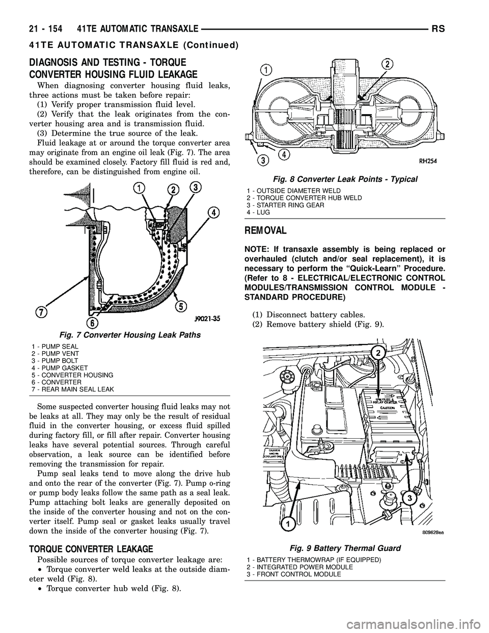
Fluid leakage at or around the torque converter area
may originate from an engine oil leak (Fig. 7). The area
should be examined closely. Factory fill fluid is red and,
therefore, can be distinguished from engine oil.
Some suspected converter housing fluid leaks may not
be leaks at all. They may only be the result of residual
fluid in the converter housing, or excess fluid spilled
during factory fill, or fill after repair. Converter housing
leaks have several potential sources. Through careful
observation, a leak source can be identified before
removing the transmission for repair.
Pump seal leaks tend to move along the drive hub
and onto the rear of the converter (Fig. 7). Pump o-ring
or pump body leaks follow the same path as a seal leak.
Pump attaching bolt leaks are generally deposited on
the inside of the converter housing and not on the con-
verter itself. Pump seal or gasket leaks usually travel
down the inside of the converter housing (Fig. 7).
TORQUE CONVERTER LEAKAGE
Possible sources of torque converter leakage are:
²Torque converter weld leaks at the outside diam-
eter weld (Fig. 8).
²Torque converter hub weld (Fig. 8).
REMOVAL
NOTE: If transaxle assembly is being replaced or
overhauled (clutch and/or seal replacement), it is
necessary to perform the ªQuick-Learnº Procedure.
(Refer to 8 - ELECTRICAL/ELECTRONIC CONTROL
MODULES/TRANSMISSION CONTROL MODULE -
STANDARD PROCEDURE)
(1) Disconnect battery cables.
(2) Remove battery shield (Fig. 9).
Fig. 7 Converter Housing Leak Paths
1 - PUMP SEAL
2 - PUMP VENT
3 - PUMP BOLT
4 - PUMP GASKET
5 - CONVERTER HOUSING
6 - CONVERTER
7 - REAR MAIN SEAL LEAK
Fig. 8 Converter Leak Points - Typical
1 - OUTSIDE DIAMETER WELD
2 - TORQUE CONVERTER HUB WELD
3 - STARTER RING GEAR
4 - LUG
Fig. 9 Battery Thermal Guard
1 - BATTERY THERMOWRAP (IF EQUIPPED)
2 - INTEGRATED POWER MODULE
3 - FRONT CONTROL MODULE
21 - 154 41TE AUTOMATIC TRANSAXLERS
41TE AUTOMATIC TRANSAXLE (Continued)
Page 1742 of 2339
TRANSMISSION CONTROL
RELAY
DESCRIPTION
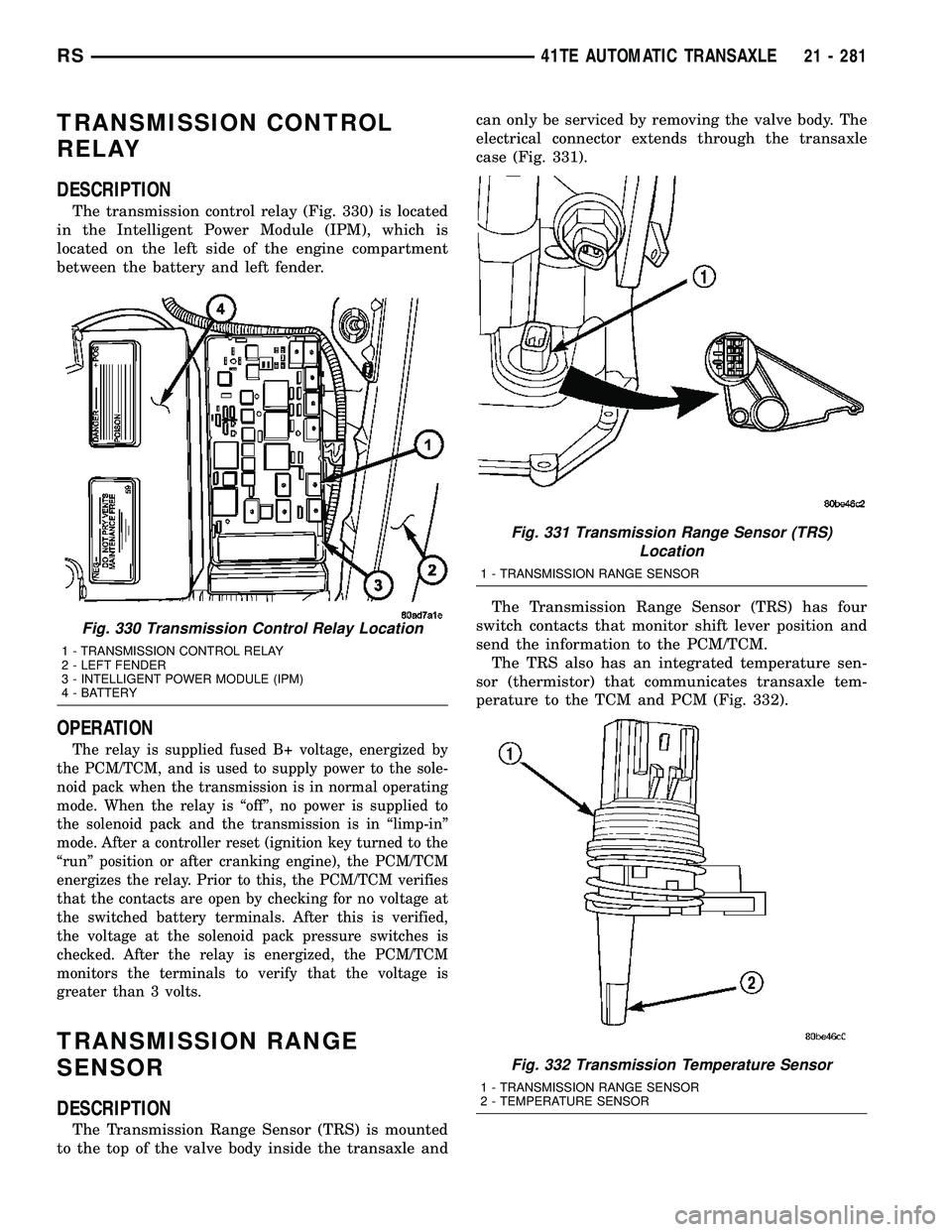
The transmission control relay (Fig. 330) is located
in the Intelligent Power Module (IPM), which is
located on the left side of the engine compartment
between the battery and left fender.
OPERATION
The relay is supplied fused B+ voltage, energized by
the PCM/TCM, and is used to supply power to the sole-
noid pack when the transmission is in normal operating
mode. When the relay is ªoffº, no power is supplied to
the solenoid pack and the transmission is in ªlimp-inº
mode. After a controller reset (ignition key turned to the
ªrunº position or after cranking engine), the PCM/TCM
energizes the relay. Prior to this, the PCM/TCM verifies
that the contacts are open by checking for no voltage at
the switched battery terminals. After this is verified,
the voltage at the solenoid pack pressure switches is
checked. After the relay is energized, the PCM/TCM
monitors the terminals to verify that the voltage is
greater than 3 volts.
TRANSMISSION RANGE
SENSOR
DESCRIPTION
The Transmission Range Sensor (TRS) is mounted
to the top of the valve body inside the transaxle andcan only be serviced by removing the valve body. The
electrical connector extends through the transaxle
case (Fig. 331).
The Transmission Range Sensor (TRS) has four
switch contacts that monitor shift lever position and
send the information to the PCM/TCM.
The TRS also has an integrated temperature sen-
sor (thermistor) that communicates transaxle tem-
perature to the TCM and PCM (Fig. 332).
Fig. 330 Transmission Control Relay Location
1 - TRANSMISSION CONTROL RELAY
2 - LEFT FENDER
3 - INTELLIGENT POWER MODULE (IPM)
4 - BATTERY
Fig. 331 Transmission Range Sensor (TRS)
Location
1 - TRANSMISSION RANGE SENSOR
Fig. 332 Transmission Temperature Sensor
1 - TRANSMISSION RANGE SENSOR
2 - TEMPERATURE SENSOR
RS41TE AUTOMATIC TRANSAXLE21 - 281
Page 2154 of 2339
²a rotary adjustment knob for temperature.
²a rotary adjustment for fan speed control.
AUTOMATIC TEMPERATURE CONTROL
Two different automatic temperature control (ATC)
heating-A/C systems are available for this model
depending on the market.
The Dual-Zone ATC system allows the driver and
front occupants to each select individual comfort tem-
peratures.
The Three-Zone ATC system allows both the driver
and front occupants and the rear intermediate occu-
pants to select individual comfort temperatures.
NOTE: Individual comfort temperatures are the per-
ceived temperature level at the individual seating
areas, NOT the actual passenger compartment air
temperature.
The ATC system includes a particulate air filter.
The filter element is the same size as the A/C evap-
orator to ensure ample capacity. A door at the base of
the HVAC housing below the glove box provides easy
access to the filter element.
The ATC computer utilizes integrated circuitry and
information carried on the programmable communi-
cations interface (PCI) data bus network to monitor
many sensors and switch inputs throughout the vehi-
cle. In response to those inputs, the internal circuitry
and programming of the ATC computer allow it to
control electronic functions and features of the ATC
system. The inputs to the ATC computer are:
²Vehicle Speed/Engine RPM± The ATC com-
puter monitors engine rpm, vehicle speed and mani-
fold absolute pressure information from the
powertrain control module (PCM).
²Coolant Temperature± ATC computer moni-
tors coolant temperature received from the PCM and
converts it to degrees Fahrenheit.
²Ambient Temperature± ATC computer moni-
tors ambient temperature from the compass mini trip
computer (CMTC) and converts it to degrees Fahren-
heit.
²Engine Miscellaneous Sensor Status±ATC
computer monitors A/C disable information from the
PCM.
²Refrigerant Pressure± ATC computer moni-
tors barometric pressure, intake air temperature,
high side pressure and methanol content as broad-
cast by the PCM.
²Door Ajar Status± The ATC computer moni-
tors driver front door, passenger front door, left rear
door, right rear door and liftgate ajar information, as
identified by the body control module (BCM), to
determine if all in-car temperatures should be main-
tained.²Dimming± The ATC computer monitors dim-
ming status from the BCM to determine the required
level of brightness and will dim accordingly.
²Vehicle Odometer± The ATC computer moni-
tors the vehicle odometer information from the BCM
to prevent flashing the vacuum-flourescent (VF) dig-
ital display icons if the manual motor calibration or
manual cool down tests have failed. Flashing of the
display icons will cease when the vehicle odometer is
greater than 3 miles.
²English/Metric± The ATC computer monitors
the English/Metric information broadcast by the
CMTC. The set temp displays for both the front and
rear control heads will be set accordingly.
²Vehicle Identification Number± The ATC
computer monitors the last eight characters of the
VIN broadcast by the PCM and compares it to the
information stored in EEPROM. If it is different, the
new number will be stored over the old one and a
motor calibration shall be initiated.
²A/C System Information± The ATC computer
will send a message for evaporator temperature too
low, fan blower relay status, evaporator sensor fail-
ure, rear window defogger relay and A/C select.
FRONT CONTROL PANEL
The front A/C-heater control and integral computer
is mounted in the instrument panel and contains:
²a power button which allows the system to be
completely turned off. The display is blank when the
system is off.
²a rocker switch that selects a cool-down rate.
LO-AUTO or HI-AUTO are displayed when the sys-
tem is in automatic operation.
²three rocker switches that select comfort temper-
atures from 15É to 30É C (59É to 85É F), which are
shown in the VF digital display. If the set temp is 15É
C (59É F) and the down button is pressed, the set
temp value will become 13É C (55É F) but the display
will show LO. If the set temp is 29É C (85É F) and the
up button is pressed, the set temp value will become
32É C (90É F) but the display will show HIGH. Tem-
peratures can be displayed in either metric or Fahr-
enheit, which is controlled from the overhead console.
²an air conditioning button that allows the com-
pressor to be turned off. A Snowflake symbol is illu-
minated when air conditioning is on, whether under
manual or automatic control.
²an air recirculation button. A Recirculation sym-
bol appears in the display when the button is
pressed, or when the system exceeds 80 percent recir-
culated air under automatic control due to high air
conditioning demand.
²a rear window defogger on/off switch. A graphic
symbol shows when the defroster is on.
RSHEATING & AIR CONDITIONING24-3
HEATING & AIR CONDITIONING (Continued)
Page 2159 of 2339
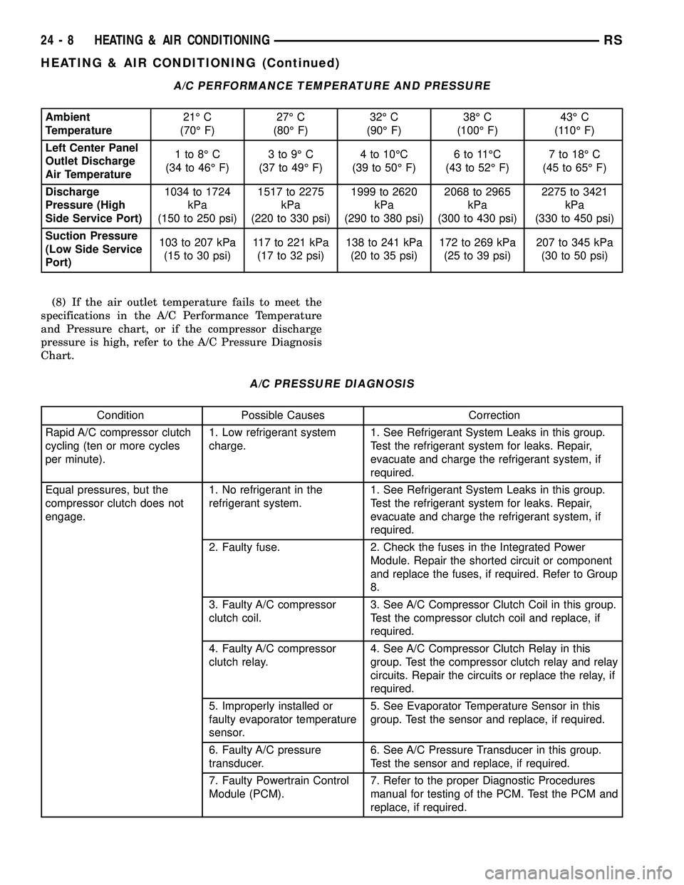
A/C PERFORMANCE TEMPERATURE AND PRESSURE
Ambient
Temperature21É C
(70É F)27É C
(80É F)32É C
(90É F)38É C
(100É F)43É C
(110É F)
Left Center Panel
Outlet Discharge
Air Temperature1to8ÉC
(34 to 46É F)3to9ÉC
(37 to 49É F)4 to 10ÉC
(39 to 50É F)6to11ÉC
(43 to 52É F)7 to 18É C
(45 to 65É F)
Discharge
Pressure (High
Side Service Port)1034 to 1724
kPa
(150 to 250 psi)1517 to 2275
kPa
(220 to 330 psi)1999 to 2620
kPa
(290 to 380 psi)2068 to 2965
kPa
(300 to 430 psi)2275 to 3421
kPa
(330 to 450 psi)
Suction Pressure
(Low Side Service
Port)103 to 207 kPa
(15 to 30 psi)117 to 221 kPa
(17 to 32 psi)138 to 241 kPa
(20 to 35 psi)172 to 269 kPa
(25 to 39 psi)207 to 345 kPa
(30 to 50 psi)
(8) If the air outlet temperature fails to meet the
specifications in the A/C Performance Temperature
and Pressure chart, or if the compressor discharge
pressure is high, refer to the A/C Pressure Diagnosis
Chart.
A/C PRESSURE DIAGNOSIS
Condition Possible Causes Correction
Rapid A/C compressor clutch
cycling (ten or more cycles
per minute).1. Low refrigerant system
charge.1. See Refrigerant System Leaks in this group.
Test the refrigerant system for leaks. Repair,
evacuate and charge the refrigerant system, if
required.
Equal pressures, but the
compressor clutch does not
engage.1. No refrigerant in the
refrigerant system.1. See Refrigerant System Leaks in this group.
Test the refrigerant system for leaks. Repair,
evacuate and charge the refrigerant system, if
required.
2. Faulty fuse. 2. Check the fuses in the Integrated Power
Module. Repair the shorted circuit or component
and replace the fuses, if required. Refer to Group
8.
3. Faulty A/C compressor
clutch coil.3. See A/C Compressor Clutch Coil in this group.
Test the compressor clutch coil and replace, if
required.
4. Faulty A/C compressor
clutch relay.4. See A/C Compressor Clutch Relay in this
group. Test the compressor clutch relay and relay
circuits. Repair the circuits or replace the relay, if
required.
5. Improperly installed or
faulty evaporator temperature
sensor.5. See Evaporator Temperature Sensor in this
group. Test the sensor and replace, if required.
6. Faulty A/C pressure
transducer.6. See A/C Pressure Transducer in this group.
Test the sensor and replace, if required.
7. Faulty Powertrain Control
Module (PCM).7. Refer to the proper Diagnostic Procedures
manual for testing of the PCM. Test the PCM and
replace, if required.
24 - 8 HEATING & AIR CONDITIONINGRS
HEATING & AIR CONDITIONING (Continued)
Page 2165 of 2339
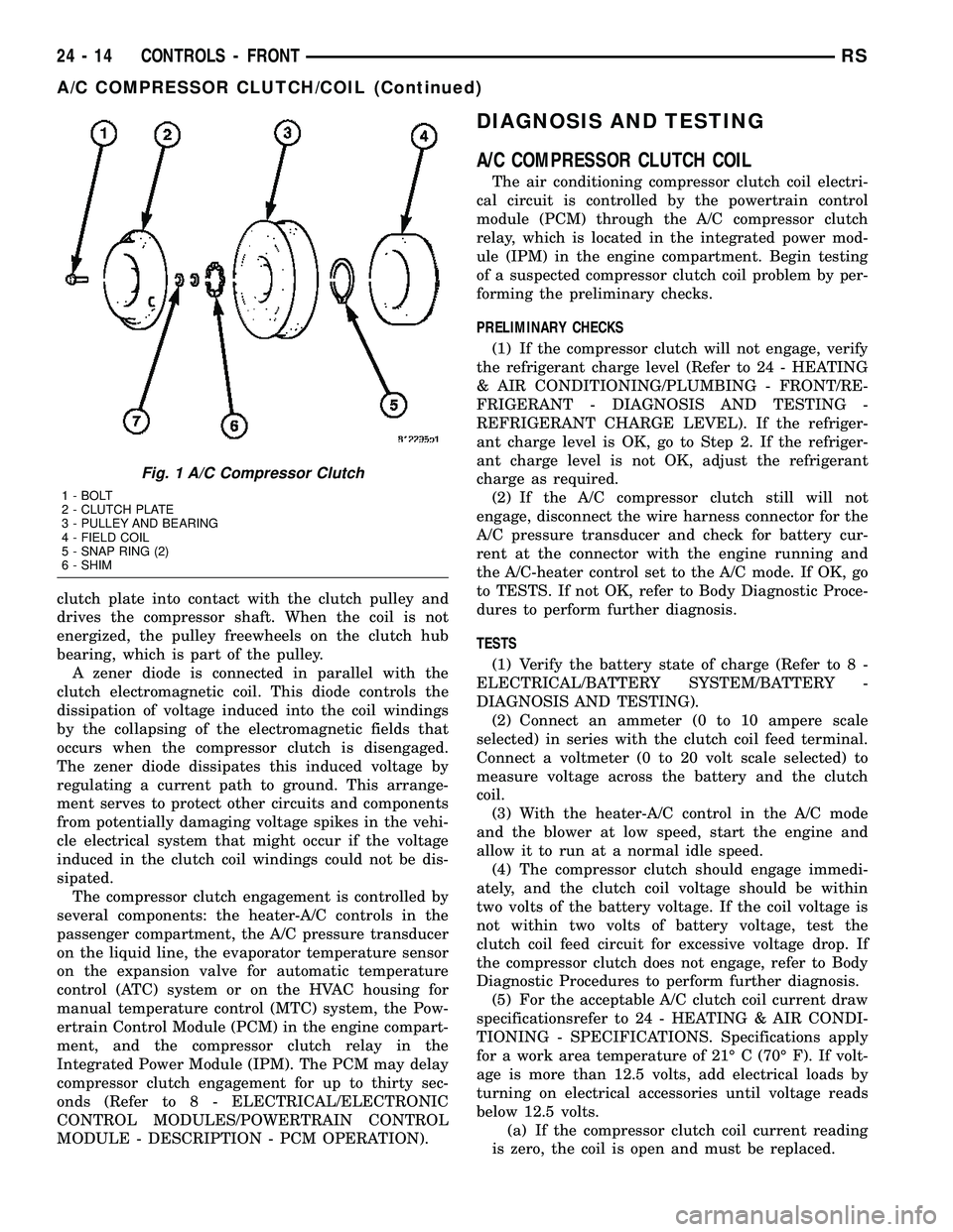
clutch plate into contact with the clutch pulley and
drives the compressor shaft. When the coil is not
energized, the pulley freewheels on the clutch hub
bearing, which is part of the pulley.
A zener diode is connected in parallel with the
clutch electromagnetic coil. This diode controls the
dissipation of voltage induced into the coil windings
by the collapsing of the electromagnetic fields that
occurs when the compressor clutch is disengaged.
The zener diode dissipates this induced voltage by
regulating a current path to ground. This arrange-
ment serves to protect other circuits and components
from potentially damaging voltage spikes in the vehi-
cle electrical system that might occur if the voltage
induced in the clutch coil windings could not be dis-
sipated.
The compressor clutch engagement is controlled by
several components: the heater-A/C controls in the
passenger compartment, the A/C pressure transducer
on the liquid line, the evaporator temperature sensor
on the expansion valve for automatic temperature
control (ATC) system or on the HVAC housing for
manual temperature control (MTC) system, the Pow-
ertrain Control Module (PCM) in the engine compart-
ment, and the compressor clutch relay in the
Integrated Power Module (IPM). The PCM may delay
compressor clutch engagement for up to thirty sec-
onds (Refer to 8 - ELECTRICAL/ELECTRONIC
CONTROL MODULES/POWERTRAIN CONTROL
MODULE - DESCRIPTION - PCM OPERATION).
DIAGNOSIS AND TESTING
A/C COMPRESSOR CLUTCH COIL
The air conditioning compressor clutch coil electri-
cal circuit is controlled by the powertrain control
module (PCM) through the A/C compressor clutch
relay, which is located in the integrated power mod-
ule (IPM) in the engine compartment. Begin testing
of a suspected compressor clutch coil problem by per-
forming the preliminary checks.
PRELIMINARY CHECKS
(1) If the compressor clutch will not engage, verify
the refrigerant charge level (Refer to 24 - HEATING
& AIR CONDITIONING/PLUMBING - FRONT/RE-
FRIGERANT - DIAGNOSIS AND TESTING -
REFRIGERANT CHARGE LEVEL). If the refriger-
ant charge level is OK, go to Step 2. If the refriger-
ant charge level is not OK, adjust the refrigerant
charge as required.
(2) If the A/C compressor clutch still will not
engage, disconnect the wire harness connector for the
A/C pressure transducer and check for battery cur-
rent at the connector with the engine running and
the A/C-heater control set to the A/C mode. If OK, go
to TESTS. If not OK, refer to Body Diagnostic Proce-
dures to perform further diagnosis.
TESTS
(1) Verify the battery state of charge (Refer to 8 -
ELECTRICAL/BATTERY SYSTEM/BATTERY -
DIAGNOSIS AND TESTING).
(2) Connect an ammeter (0 to 10 ampere scale
selected) in series with the clutch coil feed terminal.
Connect a voltmeter (0 to 20 volt scale selected) to
measure voltage across the battery and the clutch
coil.
(3) With the heater-A/C control in the A/C mode
and the blower at low speed, start the engine and
allow it to run at a normal idle speed.
(4) The compressor clutch should engage immedi-
ately, and the clutch coil voltage should be within
two volts of the battery voltage. If the coil voltage is
not within two volts of battery voltage, test the
clutch coil feed circuit for excessive voltage drop. If
the compressor clutch does not engage, refer to Body
Diagnostic Procedures to perform further diagnosis.
(5) For the acceptable A/C clutch coil current draw
specificationsrefer to 24 - HEATING & AIR CONDI-
TIONING - SPECIFICATIONS. Specifications apply
for a work area temperature of 21É C (70É F). If volt-
age is more than 12.5 volts, add electrical loads by
turning on electrical accessories until voltage reads
below 12.5 volts.
(a) If the compressor clutch coil current reading
is zero, the coil is open and must be replaced.
Fig. 1 A/C Compressor Clutch
1 - BOLT
2 - CLUTCH PLATE
3 - PULLEY AND BEARING
4 - FIELD COIL
5 - SNAP RING (2)
6 - SHIM
24 - 14 CONTROLS - FRONTRS
A/C COMPRESSOR CLUTCH/COIL (Continued)
Page 2169 of 2339
A/C COMPRESSOR CLUTCH
RELAY
DESCRIPTION
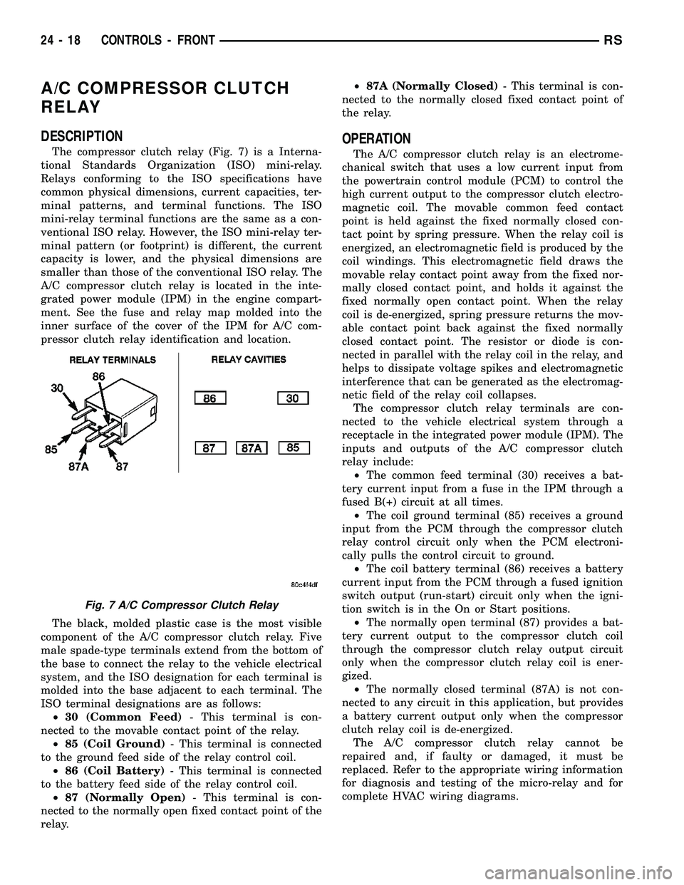
The compressor clutch relay (Fig. 7) is a Interna-
tional Standards Organization (ISO) mini-relay.
Relays conforming to the ISO specifications have
common physical dimensions, current capacities, ter-
minal patterns, and terminal functions. The ISO
mini-relay terminal functions are the same as a con-
ventional ISO relay. However, the ISO mini-relay ter-
minal pattern (or footprint) is different, the current
capacity is lower, and the physical dimensions are
smaller than those of the conventional ISO relay. The
A/C compressor clutch relay is located in the inte-
grated power module (IPM) in the engine compart-
ment. See the fuse and relay map molded into the
inner surface of the cover of the IPM for A/C com-
pressor clutch relay identification and location.
The black, molded plastic case is the most visible
component of the A/C compressor clutch relay. Five
male spade-type terminals extend from the bottom of
the base to connect the relay to the vehicle electrical
system, and the ISO designation for each terminal is
molded into the base adjacent to each terminal. The
ISO terminal designations are as follows:
²30 (Common Feed)- This terminal is con-
nected to the movable contact point of the relay.
²85 (Coil Ground)- This terminal is connected
to the ground feed side of the relay control coil.
²86 (Coil Battery)- This terminal is connected
to the battery feed side of the relay control coil.
²87 (Normally Open)- This terminal is con-
nected to the normally open fixed contact point of the
relay.²87A (Normally Closed)- This terminal is con-
nected to the normally closed fixed contact point of
the relay.
OPERATION
The A/C compressor clutch relay is an electrome-
chanical switch that uses a low current input from
the powertrain control module (PCM) to control the
high current output to the compressor clutch electro-
magnetic coil. The movable common feed contact
point is held against the fixed normally closed con-
tact point by spring pressure. When the relay coil is
energized, an electromagnetic field is produced by the
coil windings. This electromagnetic field draws the
movable relay contact point away from the fixed nor-
mally closed contact point, and holds it against the
fixed normally open contact point. When the relay
coil is de-energized, spring pressure returns the mov-
able contact point back against the fixed normally
closed contact point. The resistor or diode is con-
nected in parallel with the relay coil in the relay, and
helps to dissipate voltage spikes and electromagnetic
interference that can be generated as the electromag-
netic field of the relay coil collapses.
The compressor clutch relay terminals are con-
nected to the vehicle electrical system through a
receptacle in the integrated power module (IPM). The
inputs and outputs of the A/C compressor clutch
relay include:
²The common feed terminal (30) receives a bat-
tery current input from a fuse in the IPM through a
fused B(+) circuit at all times.
²The coil ground terminal (85) receives a ground
input from the PCM through the compressor clutch
relay control circuit only when the PCM electroni-
cally pulls the control circuit to ground.
²The coil battery terminal (86) receives a battery
current input from the PCM through a fused ignition
switch output (run-start) circuit only when the igni-
tion switch is in the On or Start positions.
²The normally open terminal (87) provides a bat-
tery current output to the compressor clutch coil
through the compressor clutch relay output circuit
only when the compressor clutch relay coil is ener-
gized.
²The normally closed terminal (87A) is not con-
nected to any circuit in this application, but provides
a battery current output only when the compressor
clutch relay coil is de-energized.
The A/C compressor clutch relay cannot be
repaired and, if faulty or damaged, it must be
replaced. Refer to the appropriate wiring information
for diagnosis and testing of the micro-relay and for
complete HVAC wiring diagrams.
Fig. 7 A/C Compressor Clutch Relay
24 - 18 CONTROLS - FRONTRS
Page 2170 of 2339
REMOVAL
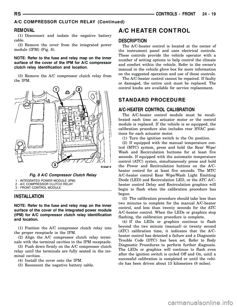
(1) Disconnect and isolate the negative battery
cable.
(2) Remove the cover from the integrated power
module (IPM) (Fig. 8).
NOTE: Refer to the fuse and relay map on the inner
surface of the cover of the IPM for A/C compressor
clutch relay identification and location.
(3) Remove the A/C compressor clutch relay from
the IPM.
INSTALLATION
NOTE: Refer to the fuse and relay map on the inner
surface of the cover of the integrated power module
(IPM) for A/C compressor clutch relay identification
and location.
(1) Position the A/C compressor clutch relay into
the proper receptacle in the IPM.
(2) Align the A/C compressor clutch relay termi-
nals with the terminal cavities in the IPM receptacle.
(3) Push down firmly on the A/C compressor clutch
relay until the terminals are fully seated in the ter-
minal cavities.
(4) Install the cover onto the IPM.
(5) Reconnect the negative battery cable.
A/C HEATER CONTROL
DESCRIPTION
The A/C-heater control is located at the center of
the instrument panel and uses electrical controls.
These controls provide the vehicle operator with a
number of setting options to help control the climate
and comfort within the vehicle. Refer to the owner's
manual in the vehicle glove box for more information
on the suggested operation and use of these controls.
The A/C-heater control cannot be repaired. If faulty
or damaged, the entire unit must be replaced. The
control knobs are available for service replacement.
STANDARD PROCEDURE
A/C-HEATER CONTROL CALIBRATION
The A/C-heater control module must be recali-
brated each time an actuator motor or the control
module is replaced. If the vehicle is so equipped, the
calibration procedure also includes rear HVAC posi-
tions for each actuator motor.
(1) Turn the ignition switch to the On position.
(2) If equipped with the manual temperature con-
trol (MTC) system, press and hold the Rear Wipe/
Wash and Recirculation buttoms for at least five
seconds. If equipped with the automatic temperature
control (ATC) systen, simultaneously press and hold
the Power and Recirculation buttons on the A/C-
heater control for at least five seconds. The MTC
A/C-heater control Rear Wipe/Wash Light Emitting
Diode (LED) and Recirculation LED, or the ATC A/C-
heater control Delay and Recirculation graphics will
begin to flash when the calibration procedure has
begun.
(3) The calibration procedure should take less than
two minutes to complete for the manual A/C-heater
control, and less than twenty seconds for the ATC
A/C-heater control. When the LEDs or graphics stop
flashing, the calibration procedure is complete.
(4) If the LEDs or graphics continue to flash
beyond the two minute (manual) or twenty second
(ATC) calibration time, it indicates that the A/C-
heater control has detected a failure and a Diagnostic
Trouble Code (DTC) has been set. Refer to Body
Diagnostic Procedures to perform further diagnosis.
The LEDs or graphics will continue to flash even
after the ignition switch is cycled Off and On, until a
successful calibration is completed or until the vehi-
cle has been driven about 13 kilometers (8 miles).
Fig. 8 A/C Compressor Clutch Relay
1 - INTEGRATED POWER MODULE (IPM)
2 - A/C COMPRESSOR CLUTCH RELAY
3 - FRONT CONTROL MODULE
RSCONTROLS - FRONT24-19
A/C COMPRESSOR CLUTCH RELAY (Continued)