2005 CHEVROLET SILVERADO ignition
[x] Cancel search: ignitionPage 451 of 580
3. Get the vehicles close enough so the jumper cables
can reach, but be sure the vehicles are not touching
each other. If they are, it could cause a ground
connection you do not want. You would not be able
to start your vehicle, and the bad grounding
could damage the electrical systems.
To avoid the possibility of the vehicles rolling, set
the parking brake �rmly on both vehicles involved
in the jump start procedure. Put an automatic
transmission in PARK (P) or a manual transmission
in NEUTRAL before setting the parking brake.
If you have a four-wheel-drive vehicle, be sure the
transfer case is in a drive gear, not in NEUTRAL.
Notice:If you leave your radio or other accessories
on during the jump starting procedure, they could
be damaged. The repairs would not be covered
by your warranty. Always turn off your radio and
other accessories when jump starting your vehicle.
4. Turn off the ignition on both vehicles. Unplug
unnecessary accessories plugged into the cigarette
lighter or accessory power outlets. Turn off the
radio and all lamps that are not needed. This will
avoid sparks and help save both batteries.
And it could save the radio!5. Open the hoods and locate the positive (+) and
negative (−) terminal locations of the other vehicle.
Your vehicle has a remote positive (+) jump
starting terminal and a remote negative (−) jump
starting terminal. You should always use these
remote terminals instead of the terminals on the
battery.
The remote positive (+) terminal is located behind a
red plastic cover, if equipped, near the engine
accessory drive bracket. To uncover the remote
positive (+) terminal, open the red plastic cover,
if equipped.
The remote negative (−) terminal is located on the
engine drive bracket on all V8 and diesel engines,
and on the thermostat housing on the 8.1L engine.
On V8 engines it is marked GND (Ground).
On V6 engines the remote negative (−) terminal is
located on a tab attached to the engine accessory
drive bracket where it is marked GND (Ground).
SeeEngine Compartment Overview on page 5-14
for more information on the location of the
remote positive (+) and remote negative (−)
terminals.
5-53
Page 493 of 580
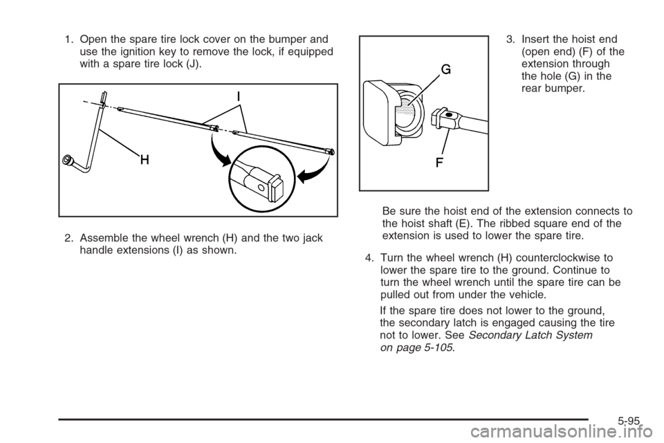
1. Open the spare tire lock cover on the bumper and
use the ignition key to remove the lock, if equipped
with a spare tire lock (J).
2. Assemble the wheel wrench (H) and the two jack
handle extensions (I) as shown.3. Insert the hoist end
(open end) (F) of the
extension through
the hole (G) in the
rear bumper.
Be sure the hoist end of the extension connects to
the hoist shaft (E). The ribbed square end of the
extension is used to lower the spare tire.
4. Turn the wheel wrench (H) counterclockwise to
lower the spare tire to the ground. Continue to
turn the wheel wrench until the spare tire can be
pulled out from under the vehicle.
If the spare tire does not lower to the ground,
the secondary latch is engaged causing the tire
not to lower. SeeSecondary Latch System
on page 5-105.
5-95
Page 523 of 580

Fuses Usage
TBC ACCYTruck Body Controller
Accessory
IGN 3 Ignition, Heated Seats
4WDFour-Wheel Drive System,
Auxiliary Battery
HTR A/C Climate Control System
LOCK (Relay)Power Door Lock Relay
(Lock Function)
HVAC 1 Climate Control System
L DOORDriver’s Door Harness
Connection
CRUISECruise Control, Power Take
Off (PTO)
UNLOCK (Relay)Power Door Lock Relay
(Unlock Function)
RR FOG LP Not Used
BRAKE Anti-Lock Brake SystemFuses Usage
DRIVER UNLOCKPower Door Lock Relay
(Driver’s Door Unlock
Function)
IGN 0 TCM
TBC IGN 0 Truck Body Controller
VEH CHMSLVehicle and Trailer High
Mounted Stoplamp
LT TRLR ST/TRN Left Turn Signal/Stop Trailer
LT TRNLeft Turn Signals and
Sidemarkers
VEH STOPVehicle Stoplamps, Brake
Module, Electronic Throttle
Control Module
RT TRLR ST/TRN Right Turn Signal/Stop Trailer
RT TRNRight Turn Signals and
Sidemarkers
BODY Harness Connector
5-125
Page 527 of 580
*1— Gasoline Engine and Diesel Engine.
*2— Gasoline Engine; ECMRPV — Diesel Engine.
*3— Gasoline Engine; FUEL HT — Diesel Engine.
*4— Gasoline Engine; ECM I — Diesel Engine.
*5— IGN/EDU
Fuses Usage
GLOW PLUGDiesel Glow Plugs and Intake
Air Heater
CUST FEED Gasoline Accessory Power
HYBRID Hybrid
STUD #1
Auxiliary Power (Single Battery
and Diesels Only)/Dual Battery
(TP2) Do not install fuse.
MBECMid Bussed Electrical Center
Power Feed, Front Seats,
Right Doors
BLOWER Front Climate Control Fan
LBECLeft Bussed Electrical
Center, Door Modules,
Door Locks, Auxiliary Power
Outlet — Rear Cargo Area
and Instrument Panel
Fuses Usage
STUD 2Accessory Power/Trailer
Wiring Brake Feed
ABS Anti-Lock Brakes
VSES/ECAS Vehicle Stability
IGN A Ignition Power
IGN B Ignition Power
LBEC 1Left Bussed Electrical Center,
Left Doors, Truck Body
Controller, Flasher Module
TRL PARK Parking Lamps Trailer Wiring
RR PARKRight Rear Parking and
Sidemarker Lamps
LR PARKLeft Rear Parking and
Sidemarker Lamps
PARK LP Parking Lamps Relay
STRTR Starter Relay
INTPARK Interior Lamps
STOP LP Stoplamps
TBC BATTTruck Body Controller
Battery Feed
5-129
Page 528 of 580

Fuses Usage
S/ROOF Sunroof
SEO B2 Off-Road Lamps
4WSVent Solenoid Canister/
QUADRASTEER™ Module
Power
RR HVAC Not Used
AUX PWRAuxiliary Power
Outlet — Console
IGN 1 Ignition Relay
PCM 1 Powertrain Control Module
ETC/ECMElectronic Throttle Control,
Electronic Brake Controller
IGN EInstrument Panel Cluster,
Air Conditioning Relay,
Turn Signal/Hazard Switch,
Starter Relay
RTD Ride Control
TRL B/U Backup Lamps Trailer Wiring
PCM BPowertrain Control Module,
Fuel Pump
F/PMP Fuel Pump (Relay)Fuses Usage
B/U LPBack-up Lamps, Automatic
Transmission Shift Lock
Control System
RR DEFOG Rear Window Defogger
HDLP-HI Headlamp High Beam Relay
PRIME Not Used
02B Oxygen Sensors
AIRBAGSupplemental In�atable
Restraint System
FRT PARKFront Parking Lamps,
Sidemarker Lamps
DRLDaytime Running Lamps
(Relay)
SEO IGN Rear Defog Relay
TBC IGN1 Truck Body Controller Ignition
HI HDLP-LT High Beam Headlamp-Left
LH HID Not Used
DRL Daytime Running Lamps
RVC Regulated Voltage Control
5-130
Page 546 of 580
At Least Once a Year
Starter Switch Check
{CAUTION:
When you are doing this inspection, the vehicle
could move suddenly. If the vehicle moves,
you or others could be injured.
1. Before you start, be sure you have enough room
around the vehicle.
2. Firmly apply both the parking brake and the regular
brake. SeeParking Brake on page 2-51.
Do not use the accelerator pedal, and be ready to
turn off the engine immediately if it starts.
3. Try to start the engine in each gear. The vehicle
should start only in PARK (P) or NEUTRAL (N).
If the vehicle starts in any other position,
contact your GM Goodwrench
®dealer for service.
Automatic Transmission Shift Lock
Control System Check
{CAUTION:
When you are doing this inspection, the vehicle
could move suddenly. If the vehicle moves,
you or others could be injured.
1. Before you start, be sure you have enough room
around the vehicle. It should be parked on a level
surface.
2. Firmly apply the parking brake. SeeParking Brake
on page 2-51.
Be ready to apply the regular brake immediately if
the vehicle begins to move.
3. With the engine off, turn the ignition to RUN, but do
not start the engine. Without applying the regular
brake, try to move the shift lever out of PARK (P)
with normal effort. If the shift lever moves out
of PARK (P), contact your GM Goodwrench
®dealer
for service.
6-12
Page 547 of 580
Ignition Transmission Lock Check
While parked, and with the parking brake set, try to turn
the ignition to LOCK in each shift lever position.
The ignition should turn to LOCK only when the
shift lever is in PARK (P).
The key should come out only in LOCK.
Contact your GM Goodwrench
®dealer if service is
required.
Parking Brake and Automatic
Transmission Park (P) Mechanism Check
{CAUTION:
When you are doing this check, your vehicle
could begin to move. You or others could be
injured and property could be damaged.
Make sure there is room in front of your
vehicle in case it begins to roll. Be ready to
apply the regular brake at once should the
vehicle begin to move.Park on a fairly steep hill, with the vehicle facing
downhill. Keeping your foot on the regular brake,
set the parking brake.
To check the parking brake’s holding ability:
With the engine running and transmission in
NEUTRAL (N), slowly remove foot pressure from
the regular brake pedal. Do this until the vehicle is
held by the parking brake only.
To check the PARK (P) mechanism’s holding ability:
With the engine running, shift to PARK (P).
Then release the parking brake followed by the
regular brake.
Contact your GM Goodwrench
®dealer if service is
required.
Underbody Flushing Service
At least every spring, use plain water to �ush any
corrosive materials from the underbody. Take care to
clean thoroughly any areas where mud and other debris
can collect.
6-13
Page 573 of 580
Hill and Mountain Roads..................................4-42
HomeLink®Wireless Control System..................2-70
HomeLink®Wireless Control System Operation.....2-71
Hood
Checking Things Under................................5-12
Release.....................................................5-13
Horn ............................................................... 3-6
How to Use This Manual...................................... ii
How to Wear Safety Belts Properly...................1-15
Hydraulic Clutch.............................................5-34
I
Ignition Positions.............................................2-22
Infants and Young Children, Restraints...............1-32
In�ation -- Tire Pressure..................................5-80
Instrument Panel
Overview..................................................... 3-4
Instrument Panel (I/P)
Brightness..................................................3-17
Cluster.......................................................3-32
J
Jump Starting.................................................5-52
K
Keyless Entry System....................................... 2-5
Keys............................................................... 2-3
L
Labelling, Tire Sidewall....................................5-74
Lamps
Auxiliary Roof Mounted Lamp........................3-17
Cargo........................................................3-19
Dome ........................................................3-17
Dome Lamp Override...................................3-18
Fog ...........................................................3-16
Front Reading.............................................3-18
LATCH System
Child Restraints...........................................1-45
Securing a Child Restraint Designed for
the LATCH System...................................1-47
Latches, Seatback............................................ 1-8
Light
Airbag Off..................................................3-34
Airbag Readiness........................................3-34
Anti-Lock Brake System Warning...................3-41
Battery Warning..........................................3-38
Brake System Warning.................................3-40
Cruise Control.............................................3-47
Four-Wheel-Drive.........................................3-48
7