2005 CHEVROLET MALIBU fuses
[x] Cancel search: fusesPage 102 of 434
PASS-Key®III+ Operation
Your vehicle is equipped with PASS-Key®III+
(Personalized Automotive Security System)
theft-deterrent system. PASS-Key
®III+ is a passive
theft-deterrent system. This means you don’t have to do
anything special to arm or disarm the system. It works
when you insert or remove the key from the ignition.
When the PASS-Key
®III+ system senses that someone
is using the wrong key, it shuts down the vehicle’s
starter and fuel systems. The starter will not work and
fuel will stop �owing to the engine. Anyone using a
trial-and-error method to start the vehicle will be
discouraged because of the high number of electrical
key codes.
When trying to start the vehicle if the engine does not
start and the security light comes on, the key may have a
damaged transponder. Turn the ignition off and try again.
If the engine still does not start, and the key appears to
be undamaged, try another ignition key. At this time,
you may also want to check the fuse, seeFuses
on page 5-83. If the engine still does not start with the
other key, your vehicle needs service. If your vehicle
does start, the �rst key may be faulty.See your dealer who can service the PASS-Key
®III+ to
have a new key made. In an emergency, contact
Chevrolet Roadside Assistance. SeeRoadside
Assistance Program on page 7-6for more information.
It is possible for the PASS-Key
®III+ decoder to
“learn” the transponder value of a new or replacement
key. Up to 10 additional keys may be programmed
for the vehicle. The following procedure is for
programming additional keys only. If all the currently
programmed keys are lost or do not operate, you must
see your dealer or a locksmith who can service
PASS-Key
®III+ to have keys made and programmed to
the system.
See your GM dealer or a locksmith who can service
PASS-Key
®III+ to get a new key blank that is cut
exactly as the ignition key that operates the system.
To program the new key do the following:
1. Verify that the new key has “+” stamped on it.
2. Insert the already programmed key in the ignition
and start the engine. If the engine will not start,
see your dealer for service.
3. After the engine has started, turn the key to off, and
remove the key.
2-20
Page 138 of 434
Turn and Lane-Change Signals
The turn signal has two upward (for right) and
two downward (for left) positions. These positions
allow you to signal a turn or a lane change.
To signal a turn, move the lever all the way up or
down to the latched position. When the turn is �nished,
the lever will return automatically.
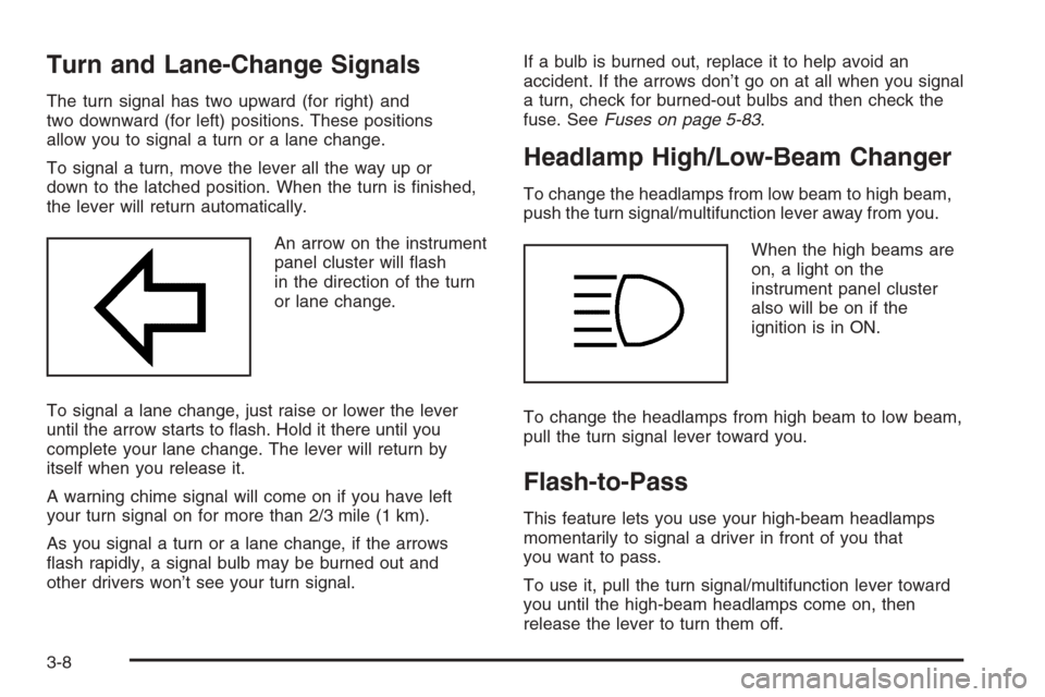
An arrow on the instrument
panel cluster will �ash
in the direction of the turn
or lane change.
To signal a lane change, just raise or lower the lever
until the arrow starts to �ash. Hold it there until you
complete your lane change. The lever will return by
itself when you release it.
A warning chime signal will come on if you have left
your turn signal on for more than 2/3 mile (1 km).
As you signal a turn or a lane change, if the arrows
�ash rapidly, a signal bulb may be burned out and
other drivers won’t see your turn signal.If a bulb is burned out, replace it to help avoid an
accident. If the arrows don’t go on at all when you signal
a turn, check for burned-out bulbs and then check the
fuse. SeeFuses on page 5-83.
Headlamp High/Low-Beam Changer
To change the headlamps from low beam to high beam,
push the turn signal/multifunction lever away from you.
When the high beams are
on, a light on the
instrument panel cluster
also will be on if the
ignition is in ON.
To change the headlamps from high beam to low beam,
pull the turn signal lever toward you.
Flash-to-Pass
This feature lets you use your high-beam headlamps
momentarily to signal a driver in front of you that
you want to pass.
To use it, pull the turn signal/multifunction lever toward
you until the high-beam headlamps come on, then
release the lever to turn them off.
3-8
Page 151 of 434
Accessory Power Outlet(s)
With accessory power outlets you can plug in auxiliary
electrical equipment such as a cellular telephone.
For vehicles with Traction Control system, the accessory
power outlets are located on the front of the center
console storage area and also inside the console
storage compartment. The compartment has notches
that allow power cords to be routed outside of the
console while the lid is closed. On vehicles without
Traction Control, both outlets are located on the front
of the center console storage area. There is also
an outlet in the rear cargo area of the MAXX.
Notice:Leaving electrical equipment on for
extended periods will drain the battery. Always turn
off electrical equipment when not in use and do
not plug in equipment that exceeds the maximum
amperage rating.
Certain electrical accessories may not be compatible
with the accessory power outlet and could result
in blown vehicle or adapter fuses. If you experience
a problem see your dealer for additional information
on accessory power outlets.Notice:Adding any electrical equipment to your
vehicle may damage it or keep other components
from working as they should. The repairs would not
be covered by your warranty. Do not use equipment
exceeding maximum amperage rating. Check
with your dealer before adding electrical equipment.
When adding electrical equipment, be sure to follow
the proper installation instructions included with
the equipment.
Notice:Improper use of the power outlet can
cause damage not covered by your warranty.
Do not hang any type of accessory or accessory
bracket from the plug because the power outlets
are designed for accessory power plugs only.
3-21
Page 292 of 434
Dinghy Towing
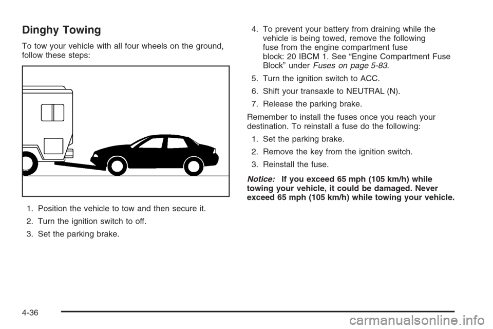
To tow your vehicle with all four wheels on the ground,
follow these steps:
1. Position the vehicle to tow and then secure it.
2. Turn the ignition switch to off.
3. Set the parking brake.4. To prevent your battery from draining while the
vehicle is being towed, remove the following
fuse from the engine compartment fuse
block: 20 IBCM 1. See “Engine Compartment Fuse
Block” underFuses on page 5-83.
5. Turn the ignition switch to ACC.
6. Shift your transaxle to NEUTRAL (N).
7. Release the parking brake.
Remember to install the fuses once you reach your
destination. To reinstall a fuse do the following:
1. Set the parking brake.
2. Remove the key from the ignition switch.
3. Reinstall the fuse.
Notice:If you exceed 65 mph (105 km/h) while
towing your vehicle, it could be damaged. Never
exceed 65 mph (105 km/h) while towing your vehicle.
4-36
Page 302 of 434
Appearance Care............................................5-73
Fabric/Carpet...............................................5-74
Vinyl...........................................................5-75
Leather.......................................................5-76
Ultra Lux Suede...........................................5-76
Instrument Panel..........................................5-76
Interior Plastic Components............................5-76
Glass Surfaces.............................................5-77
Care of Safety Belts......................................5-77
Weatherstrips...............................................5-77
Washing Your Vehicle...................................5-77
Cleaning Exterior Lamps/Lenses.....................5-78
Finish Care..................................................5-78
Windshield and Wiper Blades.........................5-78
Aluminum Wheels.........................................5-79
Tires...........................................................5-79
Sheet Metal Damage.....................................5-80
Finish Damage.............................................5-80
Underbody Maintenance................................5-80
Chemical Paint Spotting.................................5-80Vehicle Identi�cation......................................5-82
Vehicle Identi�cation Number (VIN).................5-82
Service Parts Identi�cation Label.....................5-82
Electrical System............................................5-83
Add-On Electrical Equipment..........................5-83
Headlamp Wiring..........................................5-83
Windshield Wiper Fuses................................5-83
Power Windows and Other Power Options.......5-83
Fuses.........................................................5-83
Instrument Panel Fuse Block..........................5-84
Engine Compartment Fuse Block....................5-86
Rear Compartment Fuse Block.......................5-88
Capacities and Speci�cations..........................5-91
Section 5 Service and Appearance Care
5-2
Page 383 of 434
Electrical System
Add-On Electrical Equipment
Notice:Don’t add anything electrical to your vehicle
unless you check with your dealer �rst. Some
electrical equipment can damage your vehicle and
the damage wouldn’t be covered by your warranty.
Some add-on electrical equipment can keep other
components from working as they should.
Your vehicle has an airbag system. Before attempting to
add anything electrical to your vehicle, seeServicing
Your Airbag-Equipped Vehicle on page 1-74.
Headlamp Wiring
The headlamp wiring is protected by fuses, one for each
headlamp, in the fuse block. An electrical overload
will cause the lamps to turn off. If this happens, have
your headlamp wiring checked right away.
Windshield Wiper Fuses
The windshield wiper motor is protected by an internal
circuit breaker and a fuse. If the motor overheats due to
heavy snow, etc., the wiper will stop until the motor
cools. If the overload is caused by some electrical
problem and not snow, etc., be sure to get it �xed.
Power Windows and Other Power
Options
Fuses in the fuse block protect the power windows and
other power accessories. When the current load is
too heavy, the fuse opens protecting the circuit until the
problem is �xed or goes away.
Fuses
The wiring circuits in your vehicle are protected from
short circuits by fuses and fusible thermal links in
the wiring itself.
Look at the silver-colored band inside the fuse. If the
band is broken or melted, replace the fuse. Be sure you
replace a bad fuse with a new one of the identical
size and rating.
If you ever have a problem on the road and don’t have
a spare fuse, you can borrow one that has the same
amperage. Just pick a feature of your vehicle that
you can get along without — like the radio or cigarette
lighter — and use its fuse, if it is the correct amperage.
Replace it as soon as you can.
There are three fuse blocks in your vehicle: one in the
center of the instrument panel, one in the engine
compartment and one in the trunk.
There is a fuse puller located on the instrument panel
fuse block. It can be used to easily remove fuses
from the fuse block.
5-83
Page 384 of 434
Instrument Panel Fuse Block
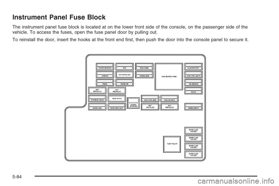
The instrument panel fuse block is located at on the lower front side of the console, on the passenger side of the
vehicle. To access the fuses, open the fuse panel door by pulling out.
To reinstall the door, insert the hooks at the front end �rst, then push the door into the console panel to secure it.
5-84
Page 385 of 434
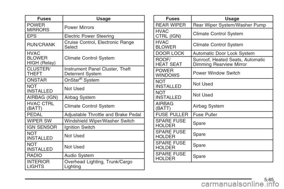
Fuses Usage
POWER
MIRRORSPower Mirrors
EPS Electric Power Steering
RUN/CRANKCruise Control, Electronic Range
Select
HVAC
BLOWER
HIGH (Relay)Climate Control System
CLUSTER/
THEFTInstrument Panel Cluster, Theft
Deterrent System
ONSTAR OnStar
®System
NOT
INSTALLEDNot Used
AIRBAG (IGN) Airbag System
HVAC CTRL
(BATT)Climate Control System
PEDAL Adjustable Throttle and Brake Pedal
WIPER SW Windshield Wiper/Washer Switch
IGN SENSOR Ignition Switch
NOT
INSTALLEDNot Used
NOT
INSTALLEDNot Used
RADIO Audio System
INTERIOR
LIGHTSOverhead Lighting, Trunk/Cargo
Lighting
Fuses Usage
REAR WIPER Rear Wiper System/Washer Pump
HVAC
CTRL (IGN)Climate Control System
HVAC
BLOWERClimate Control System
DOOR LOCK Automatic Door Lock System
ROOF/
HEAT SEATSunroof, Heated Seats, Automatic
Dimming Rearview Mirror
POWER
WINDOWSPower Window Switch
NOT
INSTALLEDNot Used
NOT
INSTALLEDNot Used
AIRBAG
(BATT)Airbag System
FUSE PULLER Fuse Puller
SPARE FUSE
HOLDERSpare
SPARE FUSE
HOLDERSpare
SPARE FUSE
HOLDERSpare
SPARE FUSE
HOLDERSpare
5-85