2005 BUICK LACROSSE height
[x] Cancel search: heightPage 7 of 410

Front Seats......................................................1-3
Manual Seats................................................1-3
Six-Way Power Seats.....................................1-4
Power Lumbar...............................................1-4
Heated Seats.................................................1-5
Reclining Seatbacks........................................1-5
Head Restraints.............................................1-7
Center Seat...................................................1-7
Rear Seats.......................................................1-8
Split Folding Rear Seat...................................1-8
Safety Belts...................................................1-10
Safety Belts: They Are for Everyone................1-10
Questions and Answers About Safety Belts......1-14
How to Wear Safety Belts Properly.................1-15
Driver Position..............................................1-15
Shoulder Belt Height Adjustment.....................1-22
Safety Belt Use During Pregnancy..................1-23
Right Front Passenger Position.......................1-23
Center Front Passenger Position.....................1-24
Rear Seat Passengers..................................1-25
Rear Safety Belt Comfort Guides....................1-27
Safety Belt Pretensioners...............................1-30
Safety Belt Extender.....................................1-30Child Restraints.............................................1-31
Older Children..............................................1-31
Infants and Young Children............................1-33
Child Restraint Systems.................................1-37
Where to Put the Restraint.............................1-40
Top Strap....................................................1-41
Top Strap Anchor Location.............................1-43
Lower Anchorages and Top Tethers for
Children (LATCH System)...........................1-43
Securing a Child Restraint Designed
for the LATCH System...............................1-45
Securing a Child Restraint in a Rear
Seat Position............................................1-46
Securing a Child Restraint in the Center
Front Seat Position....................................1-48
Securing a Child Restraint in the Right
Front Seat Position....................................1-48
Airbag System...............................................1-51
Where Are the Airbags?................................1-53
When Should an Airbag In�ate?.....................1-56
What Makes an Airbag In�ate?.......................1-57
How Does an Airbag Restrain?.......................1-57
What Will You See After an Airbag In�ates?.....1-58
Section 1 Seats and Restraint Systems
1-1
Page 28 of 410
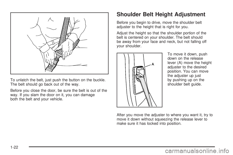
To unlatch the belt, just push the button on the buckle.
The belt should go back out of the way.
Before you close the door, be sure the belt is out of the
way. If you slam the door on it, you can damage
both the belt and your vehicle.
Shoulder Belt Height Adjustment
Before you begin to drive, move the shoulder belt
adjuster to the height that is right for you.
Adjust the height so that the shoulder portion of the
belt is centered on your shoulder. The belt should
be away from your face and neck, but not falling off
your shoulder.
To move it down, push
down on the release
lever (A) move the height
adjuster to the desired
position. You can move
the adjuster up just
by pushing up on the
shoulder belt guide.
After you move the adjuster to where you want it, try to
move it down without squeezing the release lever to
make sure it has locked into position.
1-22
Page 42 of 410
Q:What are the different types of add-on child
restraints?
A:Add-on child restraints, which are purchased by the
vehicle’s owner, are available in four basic types.
Selection of a particular restraint should take
into consideration not only the child’s weight, height
and age but also whether or not the restraint will
be compatible with the motor vehicle in which it will
be used.
For most basic types of child restraints, there are
many different models available. When purchasing a
child restraint, be sure it is designed to be used
in a motor vehicle. If it is, the restraint will have a
label saying that it meets federal motor vehicle
safety standards.
The restraint manufacturer’s instructions that come
with the restraint, state the weight and height
limitations for a particular child restraint. In addition,
there are many kinds of restraints available for
children with special needs.
{CAUTION:
Newborn infants need complete support,
including support for the head and neck. This is
necessary because a newborn infant’s neck is
weak and its head weighs so much compared
with the rest of its body. In a crash, an infant in a
rear-facing seat settles into the restraint, so the
crash forces can be distributed across the
strongest part of an infant’s body, the back and
shoulders. Infants always should be secured in
appropriate infant restraints.
1-36
Page 313 of 410
{CAUTION:
The brake wear warning sound means that
soon your brakes will not work well. That
could lead to an accident. When you hear the
brake wear warning sound, have your vehicle
serviced.
Notice:Continuing to drive with worn-out brake
pads could result in costly brake repair.
Some driving conditions or climates may cause a brake
squeal when the brakes are �rst applied or lightly
applied. This does not mean something is wrong with
your brakes.
Properly torqued wheel nuts are necessary to help
prevent brake pulsation. When tires are rotated, inspect
brake pads for wear and evenly tighten wheel nuts in
the proper sequence to GM torque speci�cations.
Brake linings should always be replaced as complete
axle sets.
Brake Pedal Travel
See your dealer if the brake pedal does not return to
normal height, or if there is a rapid increase in
pedal travel. This could be a sign of brake trouble.
Brake Adjustment
Every time you apply the brakes, with or without the
vehicle moving, your brakes adjust for wear.
Replacing Brake System Parts
The braking system on a vehicle is complex. Its many
parts have to be of top quality and work well together if
the vehicle is to have really good braking. Your
vehicle was designed and tested with top-quality GM
brake parts. When you replace parts of your braking
system — for example, when your brake linings
wear down and you need new ones put in — be sure
you get new approved GM replacement parts. If you do
not, your brakes may no longer work properly. For
example, if someone puts in brake linings that are wrong
for your vehicle, the balance between your front and
rear brakes can change — for the worse. The braking
performance you have come to expect can change
in many other ways if someone puts in the wrong
replacement brake parts.
5-37
Page 329 of 410

Tire Sidewall Labelling
Useful information about a tire is molded into its
sidewall. The examples below show a typical passenger
vehicle tire and a compact spare tire sidewall.
(A) Tire Size:The tire size is a combination of letters
and numbers used to de�ne a particular tire’s width,
height, aspect ratio, construction type and service
description. See the “Tire Size” illustration later in this
section for more detail.(B) TPC Spec (Tire Performance Criteria
Speci�cation):Original equipment tires designed to
GM’s speci�c tire performance criteria have a TPC
speci�cation code molded onto the sidewall. GM’s TPC
speci�cations meet or exceed all federal safety
guidelines.
(C) DOT (Department of Transportation):The
Department of Transportation (DOT) code indicates that
the tire is in compliance with the U.S. Department of
Transportation Motor Vehicle Safety Standards.
(D) Tire Identi�cation Number (TIN):The letters and
numbers following DOT (Department of Transportation)
code is the Tire Identi�cation Number (TIN). The
TIN shows the manufacturer and plant code, tire size,
and date the tire was manufactured. The TIN is molded
onto both sides of the tire, although only one side
may have the date of manufacture.
(E) Tire Ply Material:The type of cord and number of
plies in the sidewall and under the tread.
(F) Uniform Tire Quality Grading (UTQG):Tire
manufacturers are required to grade tires based on
three performance factors: treadwear, traction and
temperature resistance. For more information see
Uniform Tire Quality Grading on page 5-63.
(G) Maximum Cold In�ation Load Limit:Maximum
load that can be carried and the maximum pressure
needed to support that load. Passenger (P-Metric) Tire Example
5-53
Page 330 of 410

(A) Temporary Use Only:The compact spare tire or
temporary use tire has a tread life of approximately
3,000 miles (5 000 km) and should not be driven
at speeds over 65 mph (105 km/h). The compact spare
tire is for emergency use when a regular road tire
has lost air and gone �at. If your vehicle has a compact
spare tire, seeCompact Spare Tire on page 5-77
andIf a Tire Goes Flat on page 5-67.(B) Tire Ply Material:The type of cord and number of
plies in the sidewall and under the tread.
(C) Tire Identi�cation Number (TIN):The letters and
numbers following the DOT (Department of
Transportation) code is the Tire Identi�cation Number
(TIN). The TIN shows the manufacturer and plant code,
tire size, and date the tire was manufactured. The
TIN is molded onto both sides of the tire, although only
one side may have the date of manufacture.
(D) Maximum Cold In�ation Load Limit:Maximum
load that can be carried and the maximum pressure
needed to support that load.
(E) Tire In�ation:The temporary use tire or compact
spare tire should be in�ated to 60 psi (420 kPa).
For more information on tire pressure and in�ation see
In�ation - Tire Pressure on page 5-58.
(F) Tire Size:A combination of letters and numbers
de�ne a tire’s width, height, aspect ratio, construction
type and service description. The letter T as the
�rst character in the tire size means the tire is for
temporary use only.
(G) TPC Spec (Tire Performance Criteria
Speci�cation):Original equipment tires designed to
GM’s speci�c tire performance criteria have a TPC
speci�cation code molded onto the sidewall. GM’s TPC
speci�cations meet or exceed all federal safety
guidelines. Compact Spare Tire Example
5-54
Page 331 of 410
Tire Size
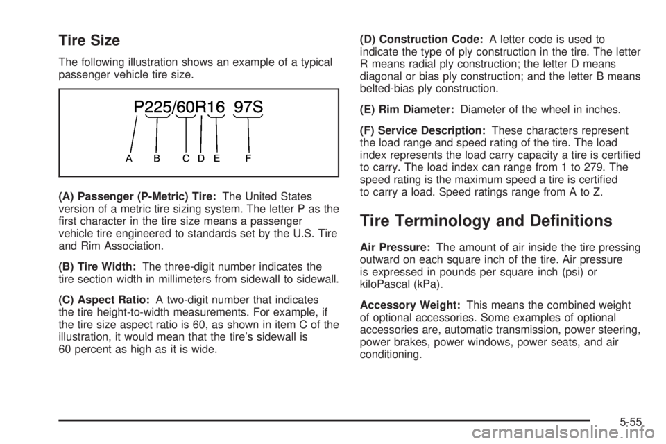
The following illustration shows an example of a typical
passenger vehicle tire size.
(A) Passenger (P-Metric) Tire:The United States
version of a metric tire sizing system. The letter P as the
�rst character in the tire size means a passenger
vehicle tire engineered to standards set by the U.S. Tire
and Rim Association.
(B) Tire Width:The three-digit number indicates the
tire section width in millimeters from sidewall to sidewall.
(C) Aspect Ratio:A two-digit number that indicates
the tire height-to-width measurements. For example, if
the tire size aspect ratio is 60, as shown in item C of the
illustration, it would mean that the tire’s sidewall is
60 percent as high as it is wide.(D) Construction Code:A letter code is used to
indicate the type of ply construction in the tire. The letter
R means radial ply construction; the letter D means
diagonal or bias ply construction; and the letter B means
belted-bias ply construction.
(E) Rim Diameter:Diameter of the wheel in inches.
(F) Service Description:These characters represent
the load range and speed rating of the tire. The load
index represents the load carry capacity a tire is certi�ed
to carry. The load index can range from 1 to 279. The
speed rating is the maximum speed a tire is certi�ed
to carry a load. Speed ratings range from A to Z.
Tire Terminology and De�nitions
Air Pressure:The amount of air inside the tire pressing
outward on each square inch of the tire. Air pressure
is expressed in pounds per square inch (psi) or
kiloPascal (kPa).
Accessory Weight:This means the combined weight
of optional accessories. Some examples of optional
accessories are, automatic transmission, power steering,
power brakes, power windows, power seats, and air
conditioning.
5-55
Page 332 of 410
Aspect Ratio:The relationship of a tire’s height to
its width.
Belt:A rubber coated layer of cords that is located
between the plies and the tread. Cords may be made
from steel or other reinforcing materials.
Bead:The tire bead contains steel wires wrapped by
steel cords that hold the tire onto the rim.
Bias Ply Tire:A pneumatic tire in which the plies are
laid at alternate angles less than 90 degrees to the
centerline of the tread.
Cold In�ation Pressure:The amount of air pressure in
a tire, measured in pounds per square inch (psi) or
kiloPascals (kPa) before a tire has built up heat from
driving. SeeIn�ation - Tire Pressure on page 5-58.
Curb Weight:This means the weight of a motor vehicle
with standard and optional equipment including the
maximum capacity of fuel, oil and coolant, but without
passengers and cargo.
DOT Markings:A code molded into the sidewall of a
tire signifying that the tire is in compliance with the U.S.
Department of Transportation (DOT) motor vehicle
safety standards. The DOT code includes the Tire
Identi�cation Number (TIN), an alphanumeric designator
which can also identify the tire manufacturer, production
plant, brand and date of production.GVWR:Gross Vehicle Weight Rating, seeLoading
Your Vehicle on page 4-29.
GAWR FRT:Gross Axle Weight Rating for the front
axle, seeLoading Your Vehicle on page 4-29.
GAWR RR:Gross Axle Weight Rating for the rear axle,
seeLoading Your Vehicle on page 4-29.
Intended Outboard Sidewall:The side of an
asymmetrical tire, that must always face outward when
mounted on a vehicle.
KiloPascal (kPa):The metric unit for air pressure.
Light Truck (LT-Metric) Tire:A tire used on light duty
trucks and some multipurpose passenger vehicles.
Load Index:An assigned number ranging from
1 to 279 that corresponds to the load carrying capacity
of a tire.
Maximum In�ation Pressure:The maximum air
pressure to which a cold tire may be in�ated. The
maximum air pressure is molded onto the sidewall.
Maximum Load Rating:The load rating for a tire at the
maximum permissible in�ation pressure for that tire.
Maximum Loaded Vehicle Weight:The sum of curb
weight; accessory weight; vehicle capacity weight;
and production options weight.
5-56