Page 25 of 48

• Switching")
25
M54engMS43/ST036/6/20000
OXYGEN SENSOR SIGNAL INFLUENCE ON INJECTOR “OPEN” TIME
The ECM monitors the:
• Amplitude of the signal (highest voltage or range sensor is producing)
• Switching time of the signal (how fast from lean to rich)
• Frequency of complete cycles (how many within a period of time)
These characteristics provide info to the ECM that reflect the overall condition of the sen-
sor.
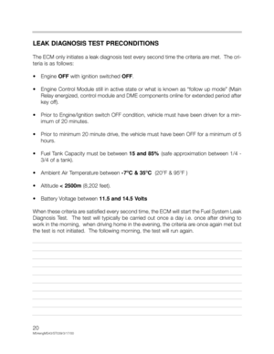
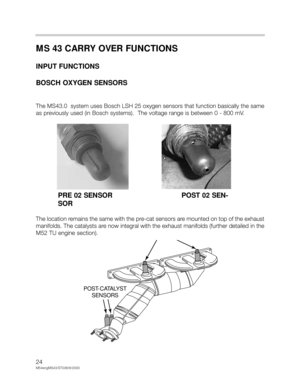
POST CATALYTIC CONVERTER SENSOR SIGNAL
The post catalyst O2 sensors monitor the efficiency of the catalyst as a requirement of OBD
II. This signal also provides feedback of the pre-catalyst sensors efficiency and can cause
the ECM to “trim” the ms injection time to correct for slight deviations.
• If the catalyst is operating efficiently, most of the remaining oxygen in the exhaust gas
is burned (lack of O2 - “constant lean signal”).
The sensor signal fluctuates slightly in the higher end of the voltage scale.
• If the post sensor shows excessive fluctuations
(which echo the scope pattern of the pre
sensor), this indicates that the catalytic converter is not functioning correctly and cannot
consume the O2 (fault set).
• If the post sensor fluctuations move out of the normal voltage “window”, this indicates
that the pre sensor is not performing properly due toslight
deterioration. These systems
can also “trim” the ms injection time to compensate for this.
The constantly changing oxygen sensor input to the ECM is needed to correct the ms
injection time to ensure that the ideal air/fuel ratio is maintained.
Page 26 of 48

26
M54engMS43/ST036/6/2000
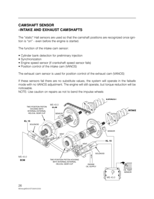
CAMSHAFT SENSOR
-INTAKE AND EXHAUST CAMSHAFTS
The "static" Hall sensors are used so that the camshaft positions are recognized once igni-
tion is “on” - even before the engine is started.
The function of the intake cam sensor:
• Cylinder bank detection for preliminary injection
• Synchronization
• Engine speed sensor (if crankshaft speed sensor fails)
• Position control of the intake cam (VANOS)
The exhaust cam sensor is used for position control of the exhaust cam (VANOS)
If these sensors fail there are no substitute values, the system will operate in the failsafe
mode with no VANOS adjustment. The engine will still operate, but torque reduction will be
noticeable.
NOTE: Use caution on repairs as not to bend the impulse wheels
KL 15 KL 15
MS42.0
SOLENOID
OIL TEMP.
SENSOR TWO POSITION PISTON HOUSING
WITH INTERNAL/EXTERNAL
HELICAL GEAR CUP TWO POSITION PISTON
HOUSING WITH
INTERNAL/EXTERNAL
HELICAL GEAR CUP
ENGINE
OIL SUPPLY VENT VENT
SOLENOID
SENSOR SENSOR
MS42
ECM
EXHAUST
INTAKE
MS42.0
ECM
MS 43.0
MS 43.0
MS 43.0
Page 27 of 48
27
M54engMS43/ST036/6/20000
CRANKSHAFT SENSOR
The crankshaft sensor is a dynamic Hall-effect sensor (mounted through the engine block),
the signal is sent the moment the crankshaft begins to rotate.
The pulse wheel is mounted directly to the crankshaft as seen on previous models.
____________________________________________________________________
____________________________________________________________________
____________________________________________________________________
MS 43.0
SMOOTH RUNNING ENGINE
NOTE SQUARE WAVEENGINE MISFIRE DETECTED
Page 28 of 48
 and")
28
M54engMS43/ST036/6/2000
MISFIRE DETECTION
As part of the CARB/OBD regulations the engine control module must determine if misfire
is occurring and also identify the specific cylinder(s) and the severity of the misfire event,
and whether it is emissions relevant or catalyst damaging. In order to accomplish these
tasks the control module monitors the crankshaft for acceleration losses during firing seg-
ments of each cylinder based on firing order.
Misfire Detection Example: M54 (6 Cyl.) with Siemens System
The misfire/engine roughness calculation is derived from the differences in the period dura-
tion (T) of individual increment gear segments. Each segment period consist of an angular
range of 120° crank angle that starts 78° before Top Dead Center (TDC).
If the expected period duration is greater than the permissible value a misfire fault for the
particular cylinder is stored in the fault memory of the ECM. Depending on the level of mis-
fire rate measured the control unit will illuminate the "Service Engine Soon" light, may cut-
off fuel to the particular cylinder and may switch lambda operation to open-loop. All mis-
fire faults are weighted to determine if the misfire is emissions relevant or catalyst damag-
ing.
_________________________________________________________________
_________________________________________________________________
_________________________________________________________________
_________________________________________________________________
_________________________________________________________________
_________________________________________________________________
_________________________________________________________________
_________________________________________________________________
_________________________________________________________________
Page 29 of 48

29
M54engMS43/ST036/6/20000
EMISSIONS RELEVANT:
During an interval of 1000 crankshaft revolutions
the misfire events of all cylinders are
added and if the sum is greater than a predetermined value a fault will be set identifying the
particular cylinder(s). The “Service Engine Soon” light will be illuminated during and after
the second cycle if the fault is again present.
CATALYST DAMAGING:
During an interval of 200 crankshaft revolutions
the misfire events of all cylinders are added
and if the sum is greater than a predetermined value a fault will be set identifying the par-
ticular cylinders(s). The “Service Engine Soon” lamp:
• On vehicles with a Siemens Control Module (M54 engines) - the lamp will immediately go
to a steady illumination since fuel to the injector(s) is removed. Fuel cut-off to the cylin-
der will resume after several (
>>7) periods of decel if crankshaft sensor adaptation is suc-
cessfully completed or the engine is shut-off and restarted.
In each case the number of misfire events permitted is dependent on engine speed, load
and temperature map.
The process of misfire detection continues well after the diagnostic drive cycle requirements
have been completed. Misfire detection is an on-going monitoring process
that is only dis-
continued under certain conditions.
Misfire detection is only disabled under the following conditions:
___________________________________________________________________
___________________________________________________________________
___________________________________________________________________
REQUIREMENTSSTATUS/CONDITION
Engine Speed< 512 RPM
Engine LoadVarying/Unstable
Throttle AngleVarying/Unstable
TimingTiming retard request active (i.e. knock
control - ASC, AGS)
Engine Start-upUp to 5 seconds after start-up
A/CUp to 0.5 seconds after A/C activation
Decel fuel cut-offActive
Rough road recognitionActive
ASC ControlActive
Page 30 of 48

30
M54engMS43/ST036/6/2000
������
��
�����
�
����������� �
����
����������������������������������� ���!��������������
"!� �#�������"��#
��������� ��$ �����"��%��$ ����
�� &�#� �����������������"��#�"!� �#���'!#��(� "�������#)(�����
*'+�,#���"� -�.� /�/�� ������
����� "��#����"��#�����������"��#�"!� �#���
��0 ���� ��$����(����( ���($
�������%
�(���$����(���(���$(�$1�$����(���������%������ ���!�"!�/�234�*�����
"!� �#���,
�(���� ���������� "��#�����"��#������ ���!�"!�/�234�*�����
"!� �#���,�(���$(�$1�$����(����( �#�($
�������%������������������ ���!�"!�/�234�*�����
"!� �#���,���� �0��(������#�� ��������� ���!�"!�/�234�*�����
"!� �#���,
$����(�����0(������#���"� -�
*������� � �0,������ ���!�"!�/�234�*�����
"!� �#���,
�(�� �0������-��-��#���"� -������� ���!�"!�/�234�*�����
"!� �#���,
�(����������$�!������ ���!�"!�/�234�*�����
"!� �#���,
� $����)���$(�$���#��(��
�������$�!������ ���!�"!�/�234�*�����
"!� �#���,
%����� ���(������������� ���!��������������
"!� �#�������"��#
�(��� 0��"��������5!0�����#������������"!� �#���
������� �"�������## � -��������������"!� �#���
�5!0����������5"��� -��� 5�(���#�- �� �����!���������"��#�����
(�0���!����5"��� -��� "��� 5�(���#(�
���� 0����� �������$����(�������������������
���"��#��(��������-���� ��������"!� �#���
������������� �"������
%���� �"����"�� �$(��� 0�������
� �� ���#���"� ������"!� �#���
�"�������%��������������"!� �#���
�"�������%�����#���0�#����"��#���0����
0�$����%�������������#
�"�������%��������"��#���0����
��!�%�����#���0�#
�����!���#���0�#�5��(�����"��$����(�����
��������"��#��������!����������"��#�����
� �� �������0�� 0�� ��� �)�"��������"!� �#��
������
���
�����
�
����������� �
����
���������������
$����$�(0���"���#��0�$��������������"��#�"!� �#���
���"���#���� �� �0����"��#�"!� �#������"���#���� ���(��������#����"��#�"!� �#������"���#���� ����(�������#
��(��#�$����$�(0�"���� "�����������"��#�"!� �#���� ����-�������� 0������� ���!����������
����"!� �#�������"��#� ������ �0� ����-�������� 0�1�� ���(�����(��#��������0������"��#"�����"����-��� ��� ���#���"� -������� ���!����������
����"!� �#�������"��#
$����$�(0�"����"���%��1�%���������� ��(�������� ���!����������
����"!� �#�������"��#
����������"��#�"!� �#���
�0� � ����� � ��������#���"�1���" �0����"��#�"!� �#��������"����� 0� � ��"����� ��������������"!� �#���
$ ����"��#��(�������������"!� �#���
$�(0������������������"!� �#���
������% ��������"����"���������������"!� �#���
��)�"� ���+��-�������� � �0�����������"��#
"!� �#���
���� �0�����������"��#
"!� �#���
"��������(��#������������"!� �#���
# ��!�"����� ����#������������"!� �#���
��)�"����"����"����"����� ��������������"!� �#���
$ ����"��#��(�������������"!� �#���
$�(0������������������"!� �#���
������% ��������"����"���������������"!� �#���
���������� ���#������ ������$���(�1�(��������� �
������* /�/� �)�"���������,
��������5��(���-��-�"�������( ���($�* �����,������ ���!����������
����"!� �#�������"��#
�(�������#���0�#�����������"��#
"!� �#���
�-����-. ����������5��(��
-��-������� �0�*����,������ ���!����������
����"!� �#�������"��#
OBD II - Misfire Faults
Page 31 of 48
31
M54engMS43/ST036/6/20000
MASS AIR FLOW SENSOR HFM
The Siemens mass air flow sensor is functionally the same as in the past. The designation
2 Type B simply indicates that it is smaller in design. The mass air meter has a diameter of
85 mm.
________________________________________________________________
________________________________________________________________
________________________________________________________________
Page 32 of 48

32
M54engMS43/ST036/6/2000
MS 43 CARRY OVER FUNCTIONS
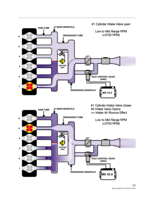
OUTPUT FUNCTIONS -VANOS CONTROL
With the double VANOS system, the valve timing is changed on both the intake and the
exhaust camshafts.
Double VANOS provides the following benefits:
• Torque increase in the low to mid (1500 - 2000 RPM) range without power loss in the
upper RPM range.
• Less incomplete combustion when idling due to less camshaft overlap (also improves
idle speed characteristics).
• Internal exhaust gas recirculation (EGR) in the part load range (reduces NOx and post-
combustion of residual gasses in the exhaust)
• Rapid catalyst warm up and lower “raw” emissions after cold start.
• Reduction in fuel consumption
Double VANOS consists of the following parts:
• Intake and exhaust camshafts with helical gear insert
• Sprockets with adjustable gears
• VANOS actuators for each camshaft
• 2 three-way solenoid switching valves
• 2 impulse wheels for detecting camshaft position
• 2 camshaft position sensors (Hall effect)
The “initial” timing is set by gear positioning (refer to the Repair Instructions for details) and
the chain tensioner. As with the previous VANOS, the hydraulically controlled actuators
move the helical geared cups to regulate camshaft timing. The angled teeth of the helical
gears cause the pushing
movement of the helical cup to be converted into a rotational
movement. This rotational movement is added to the turning of the camshafts and cause
the camshafts to “advance” or “retard”. The adjustment rate is dependent oil temperature,
oil pressure, and engine RPM.


,
the signal is sent the moment the crankshaft begins to rotate.
T")
