Page 119 of 165
Replacing front turn in-
dicator bulb
If it is not standing firmly,
the motorcycle could
topple in the course of the
operations described below.
Always make sure that the
motorcycle is stable and
firmly supported.
Make sure the ground is
level and firm and place the
motorcycle on its stand.
Switch off the ignition.
Remove screw 1. Pull the bulb housing out
of the mirror housing at the
threaded-fastener side.
Remove the bulb holder
2
from the bulb housing by
turning it counter-clockwise. Remove the bulb
3from the
bulb holder.
Installation of the bulb is the
reverse of the removal pro-
cedure.
Use a clean, dry cloth to
hold the new bulb.
Replacing rear turn in-
dicator bulb
If it is not standing firmly,
the motorcycle could
topple in the course of the
operations described below.
Always make sure that the
motorcycle is stable and
firmly supported.
Make sure the ground is
level and firm and place the
motorcycle on its stand.
Switch off the ignition.
7117zMaintenance
Page 120 of 165

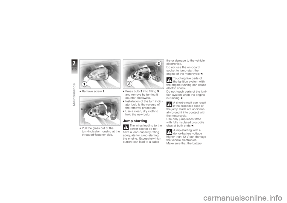
Remove screw1.
Pull the glass out of the
turn-indicator housing at the
threaded-fastener side. Press bulb
2into fitting 3
and remove by turning it
counter-clockwise.
Installation of the turn indic-
ator bulb is the reverse of
the removal procedure.
Use a clean, dry cloth to
hold the new bulb.
Jump starting
The wires leading to the
power socket do not
have a load-capacity rating
adequate for jump-starting
the engine. Excessively high
current can lead to a cable fire or damage to the vehicle
electronics.
Do not use the on-board
socket to jump-start the
engine of the motorcycle.
Touching live parts of
the ignition system with
the engine running can cause
electric shock.
Do not touch parts of the igni-
tion system when the engine
is running.
A short-circuit can result
if the crocodile clips of
the jump leads are accident-
ally brought into contact with
the motorcycle.
Use only jump leads fitted
with fully insulated crocodile
clips at both ends.
Jump-starting with a
donor-battery voltage
higher than 12 V can damage
the vehicle electronics.
Make sure that the battery
7118zMaintenance
Page 122 of 165

Be sure to read and com-
ply with the instructions for
charging the battery on the
following pages
Do not turn the battery up-
side downIf the battery is not dis-
connected, the on-board
electronics (e.g. clock, etc.)
gradually drain the battery.
This can cause the battery to
run flat. If this happens, war-
ranty claims will not be ac-
cepted.
If the motorcycle is to be out
of use for more than four
weeks, disconnect the battery
or connect a suitable trickle
charger to the battery.
BMW Motorrad
has developed a
trickle-charger specially
designed for compatibility
with the electronics of your
motorcycle. Using this charger, you can keep the
battery charged during long
periods of disuse, without
having to disconnect the
battery from the motorcycle's
on-board systems. You can
obtain additional information
from your authorised
BMW Motorrad dealer.
Charging battery when
connected
Charging the connec-
ted battery directly at the
battery terminals can damage
the vehicle electronics.
Always disconnect the battery
from the on-board circuits be-
fore recharging it with a char-
ger connected directly to the
battery posts.
If you switch on the ig-
nition and the multifunc-
tion display and telltale lights
fail to light up, the battery is
completely flat. Attempting to charge a completely flat bat-
tery via the on-board socket
can cause damage to the mo-
torcycle's electronics.
If a battery has discharged to
the extent that it is completely
flat, it has to be disconnec-
ted from the on-board circuits
and charged with the char-
ger connected directly to the
battery posts.
Only chargers suitable
for this mode of char-
ging can be used to recharge
the battery via the on-board
socket. Unsuitable chargers
could cause damage to the
motorcycle's on-board elec-
trics.
Use BMW chargers with
the part numbers 71 60
7 688 864 (220 V) or, as
applicable, 71 60 7 688 865
(110 V). If you are in doubt,
disconnect the battery from
the on-board systems and
7120zMaintenance
Page 125 of 165
Connection in the wrong
sequence increases the
risk of short-circuits.
Always proceed in the correct
sequence.
Never install the battery
without the protective cap.
Connect battery positive
lead 3first.
The connect battery negat-
ive lead 2.
Install the cover of the bat-
tery compartment. Install the battery com-
partment cover, noting
latches
2.
Install screws 1.
Switch on the ignition.
Fully open the throttle once
or twice.
The engine management
system registers the
throttle-valve position.
Setting the clock ( 44)
7123zMaintenance
Page 135 of 165
Threaded fastenersActivityType of threaded connection Tightening
torquesFront wheel
Front brake caliper, wheel carrier
installedM8 x 32 -10.9
30 Nm (Left)
M8 x 32 -10.9 30 Nm (Right)
Clamping screw for quick-release
axle in wheel carrier M8 x 30
19 Nm
Quick-release axle in threaded
bush M24 x 1.5
50 Nm
Rear wheel
Silencer to rear footrest, right M8 x 30 28 Nm
Silencer to manifold M8 - 10.9 self-locking, Optimoly TA 35 Nm
Rear wheel to wheel flange M10 x 43 x 1.25 60 Nm
M10 x 40 x 1.25 60 Nm
9133zTechnical data
Page 138 of 165
Riding specificationsTop speed>200 km/h
Acceleration 0-100 km/h 2.8 sClutchClutch, typeMultiplate clutch running in oil bathTransmissionGearbox, typeClaw-shift 6-speed cassette gearbox, integ-
rated into engine block
Gear ratios
Total transmission ratio, 1st gear 2.521
Total transmission ratio, 2nd gear 1.842
Total transmission ratio, 3rd gear 1.455
Total transmission ratio, 4th gear 1.287
Total transmission ratio, 5th gear 1.143
Total transmission ratio, 6th gear 1.015
9136zTechnical data
Page 156 of 165

A
Abbreviations and symbols, 6
Anti-theft alarm, 17
B
BatteryCharging battery when
connected, 120
Charging the battery when
disconnected, 121
Installation, 122
Removal, 121
Warning, battery charge
current, 26
Brake fluid Checking level, front, 97
Checking level, rear, 98
Brake pads Checking front, 95
Checking rear, 96
Brakes Technical data, 138
Breakdown assistance kit, 89 Bulbs
General instructions, 112
Replacing brake-light
bulbs, 116
Replacing front turn
indicator bulb, 117
Replacing high-beam
headlight bulb, 114
Replacing low-beam
headlight bulb, 112
Replacing parking-light
bulb, 115
Replacing rear light
bulbs, 116
Replacing rear turn indicator
bulb, 117
Technical data, 140
Warning, bulb failure, 26, 27
C
Case Adapting, 89
Adjusting, 86
Closing, 86
Installing, 88 Opening, 86
Removing, 87
Clock, 20 Adjusting, 17, 44
Clutch Fluid reservoir, 11, 13
Technical data, 136
Confirmation of maintenance work, 147
Coolant Temperature gauge, 21
Warning, coolant temperat-
ure, 24
E
Electrics Technical data, 139
Emergency off switch (kill switch), 16, 45
Engine Technical data, 134
Temperature gauge, 20
Warning, engine electron-
ics, 25
11154zIndex
Page 158 of 165

LightsSwitching off the parking
lights, 48
Switching on the high-beam
headlight, 47
Switching on the low-beam
headlight, 47
Switching on the parking
lights, 48
Switching on the side
lights, 47
M
Multifunction display, 17, 20
O
On-board computer Ambient temperature, 43
Average consumption, 43
Average speed, 42
Pushbutton, 15
Resetting average con-
sumption, 43
Resetting average
speed, 42 Residual range, 42
Selecting readings, 41
Tripmaster function, 41
P
Power socket, 11, 13
Pre-ride check, 63
R
Rear wheel stand Installing, 111
Refuelling, 76
Reserve Warning, 24
Residual range, 40, 42
Restoring to use, 129
Rev. counter, 17
Running gear Technical data, 137
S
Seat Installation, 51
Lock, 11, 13
Removal, 50
Service, 144 Side stand
Starting the engine, 62
Speedometer, 17
Spring preload, rear Adjusting, 11, 13, 54
Starter, 16
Steering lock, 37
Suspension damping, rear Adjusting, 11, 13, 54
T
Technical data Brakes, 138
Bulbs, 140
Clutch, 136
Electrics, 139
Engine, 134
Engine oil, 135
Final drive, 137
Frame, 141
Fuel, 135
Running gear, 137
Transmission, 136
Wheels and tyres, 138
Telltale lights, 17
11156zIndex