Page 9 of 16

EN/9
Retrofit kit No. 65 50 0 143 549
Installation Instructions No. 01 29 0 143 558 Issue date: 03.2002
6. To install the aerial
0
0
00
Coupé only
Connect the aerial
D
with the journal (1) between the
interior and exterior shell of the bumper (2).
Secure the aerial
D
to the existing holes using expanding
rivets
I
.
0
Secure the aerial connection cable (2) to the existing hole
in the holder (1) using a cable tie
M
.
0
Lay the aerial connection cable (1) in the holding lugs (2)
of the holder (3) to the right-hand side.
Install the right-hand aerial.
0
Saloon only
Install the spacer
F
to the aerial
D
using an expanding
rivet
J
.
Place the aerial
D
on the bumper (4) as shown:
- Contact point (6): Aerial
D
flush with the shaped
section of the bumper (5)
- Contact point (1): Aerial
D
butt-to-butt with the holder
(7)
Align the aerial
D
so that the spacer
F
lays on the bumper
(4) without being stressed.
Remove the aerial
D
.
046 0602 Z
I
D
2
1
1M
2
046 0603 Z
046 0604 Z
123
046 0672 Z
5
D
1
4
67
FJ
F
D
J
Page 10 of 16
EN/10
Retrofit kit No. 65 50 0 143 549
Installation Instructions No. 01 29 0 143 558 Issue date: 03.2002
6. To install the aerial
0
0
0
00
Clean the gluing areas. Use the contact points (see
above) and follow the instructions for use for
Sikaflex-221.
"
Affix the aerial
D
in the marked area (2) and to the spacer
F
on the bumper (1) using Sikaflex-221.
00f
Lay the aerial connection cable (1) to the right-hand side
of the bumper.
Secure the aerial connection cable (1) to the existing
holes in the bumper (2) using cable ties
M
.
Install the right-hand aerial.
0
Cars with towing hitch only
The lugs on the capacitor (2) must finish flush with
the support (1).
"
Position the capacitor (2) in the centre as shown, and
mark the hole on the support.
Drill the hole in the support (1) with a 5.5 mm drill bit.
0
Secure the capacitor (2) to the hole in the support (1)
using a hexagonal screw
H
and hexagonal nut
N
.
046 0673 Z
21
FD
046 0677 Z
1
2
M
046 0662 Z
1
3
2
046 0671 Z
1
H
N
2
Page 11 of 16
EN/11
Retrofit kit No. 65 50 0 143 549
Installation Instructions No. 01 29 0 143 558 Issue date: 03.2002
6. To install the aerial
0
0
0To install the aerial0
Cars without a towing hitch only
Secure the capacitor to the shock absorber (2) using a
hexagonal nut
K
.
0
All cars
Remove the sealing stopper from the left rear panel (2).
Insert the cable grommet with the aerial cables (1) into
the exposed opening.
Install the bumper.
046 0664 Z
2
K1
046 0589 Z
2
1
Page 12 of 16

EN/12
Retrofit kit No. 65 50 0 143 549
Installation Instructions No. 01 29 0 143 558 Issue date: 03.2002
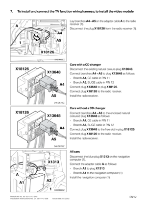
7. To install and connect the TV function wiring harness; to install the video module
0
0
0
00
Lay branches
A4 - A5
on the adapter cable
A
to the
radio
receiver (1).
Disconnect the plug
X18126
from the radio receiver (1).
0
Cars with a CD changer
Disconnect the existing natural colours plug
X13648
.
Connect branches
A4 - A5
to plug
X13648
as follows:
- Branch
A4
, GE cable in PIN 11
- Branch
A5
, BL/GE cable in PIN 12
Connect plug
X13648
to plug
X18126
.
Connect plug
X18126
to the radio receiver.
Install the radio receiver.
0Cars without a CD changer
Connect branches A4 - A5 to the enclosed natural
coloured plug X13648 as follows:
- Branch A4, GE cable in PIN 11
- Branch A5, BL/GE cable in PIN 12
Connect plug X13648 to the free slot in plug X18126.
Connect plug X18126 to the radio receiver.
Install the radio receiver.
0All cars
Disconnect the blue plug X1313 on the navigation
computer (1).
Connect the adapter cable A as follows:
- Branch A2 to plug X1313
- Branch A1 to the navigation computer (1)
Install the navigation computer (1).
046 0665 Z
GPSNAVIGATION SYSTEM
A4
A51
X18126
A
046 0678 Z
X18126
A4
X13648
A5
046 0678 Z
X18126
A4
X13648
A5
046 0666 Z
X1313
A2A1
A
1
Page 13 of 16
EN/13Retrofit kit No. 65 50 0 143 549
Installation Instructions No. 01 29 0 143 558 Issue date: 03.2002
7. To install and connect the TV function wiring harness; to install the video module
0
0
0To install and connect the TV function wiring harness; to install the video module
00
Place the speed nut G on the module holder (1).
0Secure the video module E into the module holder and
secure it with the hexagonal screw H.
0Connect the aerial cable (1) to the same coloured
TV aerial cables 1 B and TV 2 C.
Lay the aerial cables TV 1 B and TV 2 C to the video
module E.
0Connect branches A3 and A6 to the same coloured
cables on the video module E.
Connect the aerial cables TV 1 B and TV 2 C to the video
module E.
046 0667 Z
GPSNAVIGATION SYSTEM
1
G
046 0668 Z
GPSNAVIGATION SYSTEM
H
E
046 0669 Z
GPSNAVIGATION SYSTEM
B1
C
E
046 0670 Z
GPSNAVIGATION SYSTEM
A3
A6
B
C
E
Page 14 of 16
EN/14Retrofit kit No. 65 50 0 143 549
Installation Instructions No. 01 29 0 143 558 Issue date: 03.2002
8. Concluding work and coding
- Re-assemble the car
- Connect the battery
- Encode the TV function using DIS or MoDiC via path Retrofit.
- Check the function of the TV function
Page 15 of 16
EN/15Retrofit kit No. 65 50 0 143 549
Installation Instructions No. 01 29 0 143 558 Issue date: 03.2002
9. TV function circuit diagram
0
046 0620 Z
X18806X18804 X13648
X18344X13016X13317
A112A112
X1313 X1313
30,35
WSRTGE
100,5
BR
10,75
RTGN
9
18
180,5
GE
90,5
BLGE
12120,5
BRRT
330,35
WSRTGE
10100,5
BR
110,75
RTGN
180,5
BL/GE
90,5
GE
11
12 4
180,35
SW
140,35
660,35
SW
15150,35
550,35
SW
14140,35
770,35
SW
16160,35
13170,35
SW
160,35
1780,35
GE
1570,35
8160,35
SW
A197A197 N9
Page 16 of 16
EN/16Retrofit kit No. 65 50 0 143 549
Installation Instructions No. 01 29 0 143 558 Issue date: 03.2002
9. TV function circuit diagram
Legend
Cable coloursA112Navigation computer
A197Video module
N9Radio receiver
X1313 Blue 18-pin socket casing on the navigation computer and blue 18-pin plug casing to the
standard wiring harness
X13016Terminal 31 connector
X13317Terminal 30 connector
X1364812-pin natural socket casing on the radio receiver
X18344I bus connector
X18804Blue 18-pin plug on the video module
X18806Natural coloured 18-pin plug on the video module
RT red
SW black
GN green
BR brown
GE yellow
WS white
BL blue