Page 49 of 92
Downloaded from www.Manualslib.com manuals search engine 51
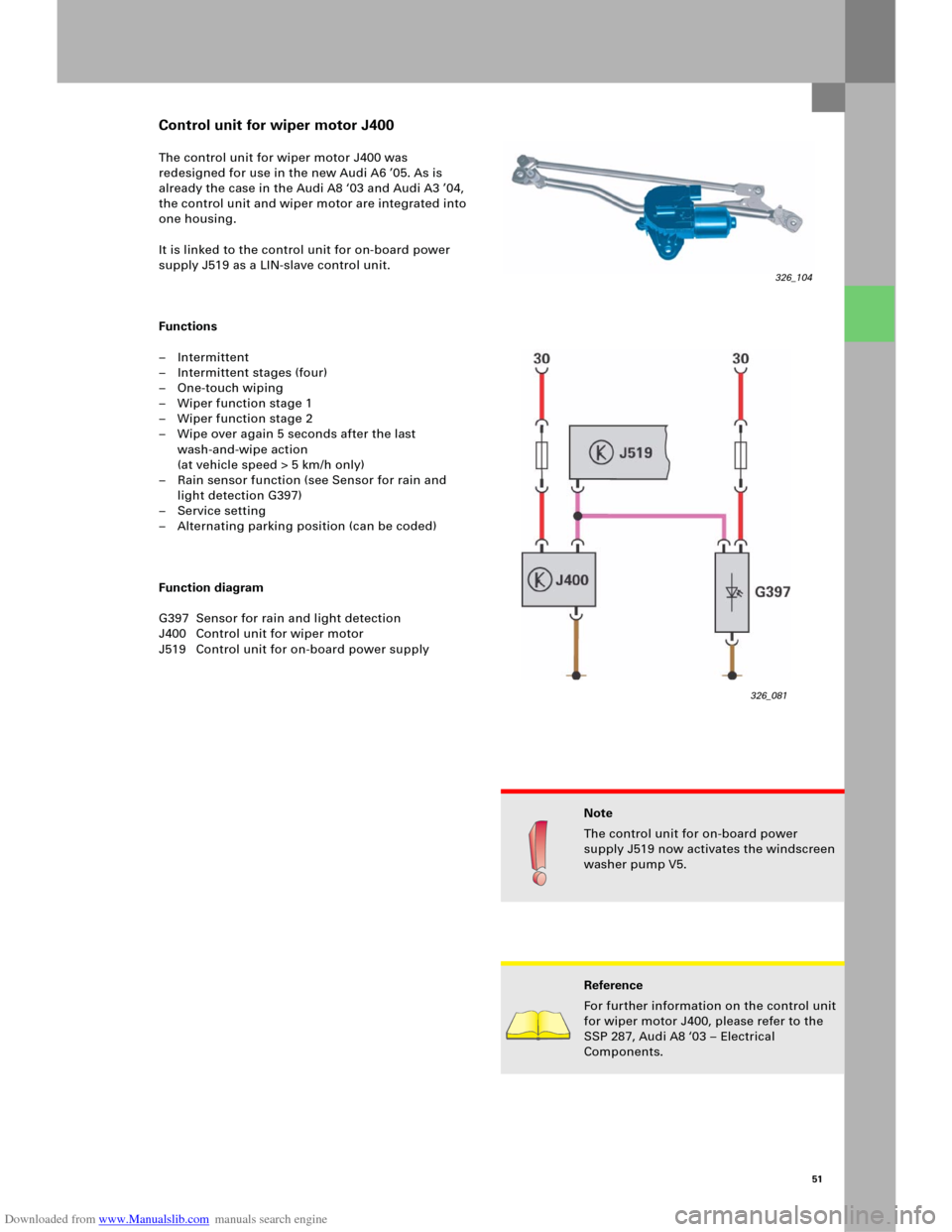
The control unit for wiper motor J400 was
redesigned for use in the new Audi A6 ’05. As is
already the case in the Audi A8 ‘03 and Audi A3 ’04,
the control unit and wiper motor are integrated into
one housing.
It is linked to the control unit for on-board power
supply J519 as a LIN-slave control unit.
Functions
– Intermittent
– Intermittent stages (four)
–One-touch wiping
– Wiper function stage 1
– Wiper function stage 2
– Wipe over again 5 seconds after the last
wash-and-wipe action
(at vehicle speed > 5 km/h only)
– Rain sensor function (see Sensor for rain and
light detection G397)
– Service setting
– Alternating parking position (can be coded)
Function diagram
G397 Sensor for rain and light detection
J400 Control unit for wiper motor
J519 Control unit for on-board power supply
Reference
For further information on the control unit
for wiper motor J400, please refer to the
SSP 287, Audi A8 ‘03 – Electrical
Components.
Note
The control unit for on-board power
supply J519 now activates the windscreen
washer pump V5.
326_081
Control unit for wiper motor J400
326_104
Page 50 of 92
Downloaded from www.Manualslib.com manuals search engine 52
An additional on-board power supply control unit is
needed in the Audi A6 ´05 because of the huge
range of functions it offers.
Functions
Control unit 2 for on-board power supply J520
includes the following functions:
– Activate the solenoid valve for Servotronic N119
– Sliding roof convenience opening/closing
– Speed signal for sliding roof
– Tilt sensor for anti-theft warning system
– Glove compartment release
Installation position
Control unit 2 for on-board power supply is located
behind the glove compartment in the module
carrier on the passenger’s side.
Versi on s
Two different versions of control unit 2 for on-board
power supply are available, depending on the
vehicle equipment.
–Low version
(only includes glove compartment release and
Servotronic function only)
–High version
(also with sliding roof/anti-theft warning system)
Convenience electrics
Control unit 2 for on-board power supply J520
326_103
Page 51 of 92
Downloaded from www.Manualslib.com manuals search engine 53
Function diagram
326_082
Legend
E316 Glove compartment button
J520 Control unit 2 for on-board power supply
N119 Solenoid valve for Servotronic
V1 Motor for sliding roof
V327 Motor for glove compartment releaseAdditional signals
1CAN Convenience High
2CAN Convenience Low
Page 52 of 92
Downloaded from www.Manualslib.com manuals search engine 54
The tilt sensor for the anti-theft warning system is
integrated directly in control unit 2 for on-board
power supply J520 in the new Audi A6 ‘05.
The fluid-filled sensor registers changes in the
vehicle tilt both transversely and longitudinally,
thereby preventing incorrect triggering as a result of
shaking through viscous fluid and electronic delay.
The current tilt values can be read out using
measured-value blocks.
Diagnosis
– Measured-value blocks
Measured-value blocks are available for the
following functions:
– Servotronic
– Sliding roof
– Tilt angle
–Actuator test
Checks can be carried out for the following
functions, depending on the version:
– Glove compartment release
– Servotronic valve
– Sliding roof activation (can be measured
using a multimeter on the on-board power
supply control unit, sliding roof does not
open, however, if it is not released by the
central control unit for the convenience
system)
–Coding
The High-Line version of control unit 2 for
on-board power supply J520 must be coded for
the following functions:
– Tilt sensor (with or without)
– Sliding roof (with or without)
Convenience electrics
Note
The tilt sensor function can be switched off
using a button in the driver’s door panel.
Reference
For further information on the tilt sensor
function, please refer to the SSP 254,
Audi A4 ‘01 – Technology.
Tilt sensor for anti-theft warning system
Page 53 of 92
Downloaded from www.Manualslib.com manuals search engine 55
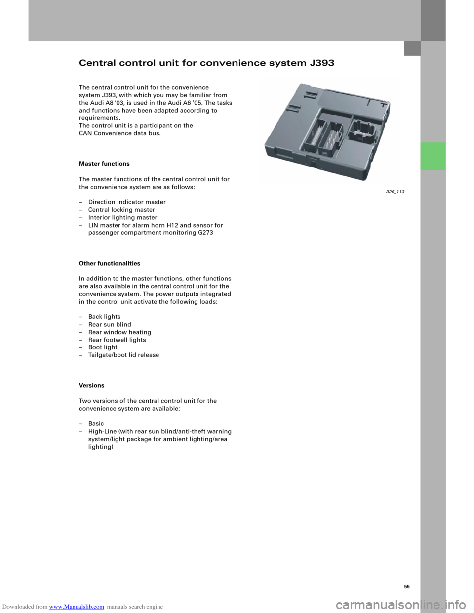
The central control unit for the convenience
system J393, with which you may be familiar from
the Audi A8 '03, is used in the Audi A6 ’05. The tasks
and functions have been adapted according to
requirements.
The control unit is a participant on the
CAN Convenience data bus.
Master functions
The master functions of the central control unit for
the convenience system are as follows:
– Direction indicator master
– Central locking master
– Interior lighting master
– LIN master for alarm horn H12 and sensor for
passenger compartment monitoring G273
Other functionalities
In addition to the master functions, other functions
are also available in the central control unit for the
convenience system. The power outputs integrated
in the control unit activate the following loads:
– Back lights
–Rear sun blind
– Rear window heating
– Rear footwell lights
–Boot light
– Tailgate/boot lid release
Ve rs i on s
Two versions of the central control unit for the
convenience system are available:
–Basic
– High-Line (with rear sun blind/anti-theft warning
system/light package for ambient lighting/area
lighting)
Central control unit for convenience system J393
326_113
Page 54 of 92
Downloaded from www.Manualslib.com manuals search engine 56
326_121
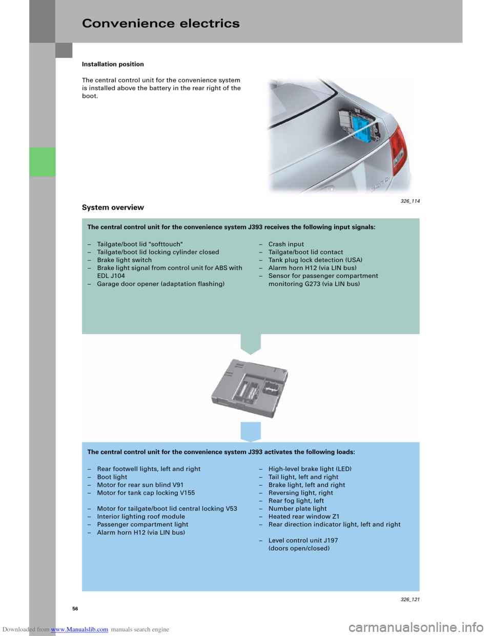
Installation position
The central control unit for the convenience system
is installed above the battery in the rear right of the
boot.
System overview
Convenience electrics
– Tailgate/boot lid "softtouch"
– Tailgate/boot lid locking cylinder closed
– Brake light switch
– B rake li ght signal from control u ni t fo r ABS with
EDL J104
– Garage door opener (adaptation flashing)– Crash input
– Tailgate/boot lid contact
–Tank plug lock detection (USA)
– Alarm horn H12 (via LIN bus)
– Sensor for passenger compartment
monitoring G273 (via LIN bus)
– Rear footwell lights, left and right
– Boot light
– Motor for rear sun blind V91
– Motor for tank cap locking V155
– Motor for tailgate/boot lid central locking V53
– Interior lighting roof module
– Passenger compartment light
– Alarm horn H12 (via LIN bus)– High-level brake light (LED)
– Tail light, left and right
–Brake light, left and right
– Reversing light, right
–Rear fog light, left
– Number plate light
– Heated rear window Z1
– Rear direction indicator light, left and right
– Level control unit J197
(doors open/closed) The central control unit for the convenience system J393 receives the following input signals:
The central control unit for the convenience system J393 activates the following loads:
326_114
Page 55 of 92
Downloaded from www.Manualslib.com manuals search engine 57
Interior lighting control
Standard equipment function
The standard function includes activating the inside
light in the roof lining, the front footwell lights, the
glove compartment light and the boot light.
The central control unit for the convenience
system J393 activates the inside light in the roof
lining, the boot light and the glove compartment
light directly via its own outputs and inputs. The
control unit for on-board power supply J519
activates the front footwell lights via CAN messages
from the central control unit for the convenience
system J393.
Additional equipment function (light package)
The light package additional equipment also
includes a door contour light in every door as well
as footwell lights (front and rear), which are based
on LED technology. The door contour lighting is
activated by the door control unit, which receives
the CAN messages for this from the central control
unit for the convenience system J393.
Page 56 of 92
Downloaded from www.Manualslib.com manuals search engine 58
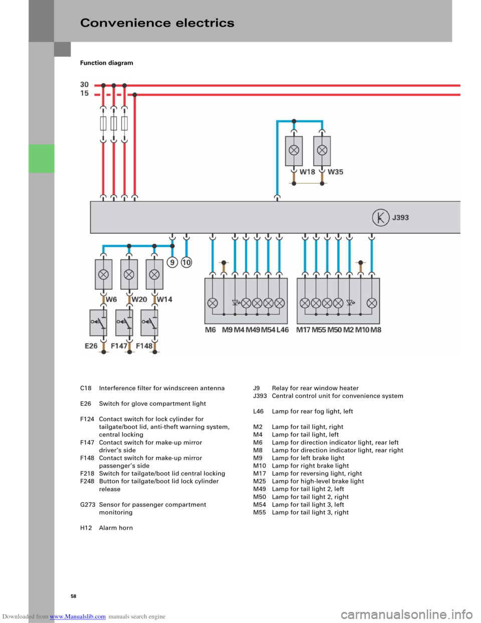
Function diagram
Convenience electrics
C18 Interference filter for windscreen antenna
E26 Switch for glove compartment light
F124 Contact switch for lock cylinder for
tailgate/boot lid, anti-theft warning system,
central locking
F147 Contact switch for make-up mirror
driver’s side
F148 Contact switch for make-up mirror
passenger’s side
F218 Switch for tailgate/boot lid central locking
F248 Button for tailgate/boot lid lock cylinder
release
G273 Sensor for passenger compartment
monitoring
H12 Alarm hornJ9 Relay for rear window heater
J393 Central control unit for convenience system
L46 Lamp for rear fog light, left
M2 Lamp for tail light, right
M4 Lamp for tail light, left
M6 Lamp for direction indicator light, rear left
M8 Lamp for direction indicator light, rear right
M9 Lamp for left brake light
M10 Lamp for right brake light
M17 Lamp for reversing light, right
M25 Lamp for high-level brake light
M49 Lamp for tail light 2, left
M50 Lamp for tail light 2, right
M54 Lamp for tail light 3, left
M55 Lamp for tail light 3, right