Page 288 of 457
5-66
OIL PAN AND OIL PUMPENG
NOTE:
EAS00362
REMOVING THE OIL PAN
1. Remove:
�oil level switch
1
�oil pan 2
�oil pan gasket
�dowel pins
Loosen each bolt 1 / 4 of a turn at a time, in
stages and in a crisscross pattern. After all of
the bolts are fully loosened, remove them.
CHECKING THE SPROCKET AND CHAIN
1. Check:
�oil / water pump assembly drive sprocket
1
Cracks / damage / wear � Replace the de-
fective part(-s).
2. Check:
�oil / water pump assembly drive chain
1
Damage / stiffness � Replace the oil / water
pump assembly drive chain and oil / water
pump assembly drive sprocket as a set.
ProCarManuals.com
Page 293 of 457
5-71
OIL PAN AND OIL PUMPENG
12 Nm (1.2 m�kg, 8.7 ft�lb)
10 Nm (1.0 m�kg, 7.2 ft�lb)
43Nm (4.3 m�kg, 31 ft�lb)
WARNING
NOTE:
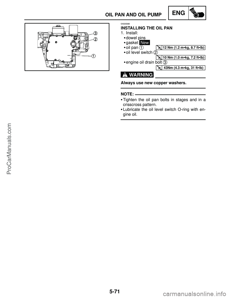
EAS00380
INSTALLING THE OIL PAN
1. Install:
�dowel pins
�gasket
New
�oil pan
1
�oil level switch 2
�engine oil drain bolt 3
Always use new copper washers.
�Tighten the oil pan bolts in stages and in a
crisscross pattern.
�Lubricate the oil level switch O-ring with en-
gine oil.
ProCarManuals.com
Page 303 of 457
5-81
CONNECTING RODS AND PISTONSENG
NOTE:
NOTE:
Piston ring side clearance
Top ring
0.030 � 0.065 mm
(0.0012 � 0.0026 in)
: 0.115 mm (0.0045 in)
2nd ring
0.020 � 0.055 mm
(0.0008 � 0.002 in)
: 0.115 mm (0.0045 in)
2. Install:
�piston ring
(into the cylinder)
Level the piston ring into the cylinder with the
piston crown.
a5 mm (0.20 in)
3. Measure:
�piston ring end gap
Out of specification � Replace the piston
ring.
The oil ring expander spacer’s end gap cannot
be measured. If the oil ring rail’s gap is exces-
sive, replace all three piston rings.
Piston ring end gap
Top ring
0.15 � 0.25 mm
(0.0059 � 0.0098 in)
: 0.50 mm (0.0197 in)
2nd ring
0.30 � 0.45 mm
(0.0118 � 0.0177 in)
: 0.80 mm (0.0315 in)
Oil ring
0.10 � 0.40 mm
(0.0039 � 0.0158 in)
CHECKING THE PISTON PINS
The following procedure applies to all of the pis-
ton pins.
1. Check:
�piston pin
Blue discoloration / grooves � Replace the
piston pin and then check the lubrication sys-
tem.
ProCarManuals.com
Page 340 of 457
6-12
WATER PUMPCOOL
Order Job / Part Q’ty Remarks
1
2
3
4Removing the impeller shaft
Oil / water pump assembly and oil
pump rotor
Water pump cover
O-ring
Pin
Impeller shaft (along with the impeller)1
1
2
1
Remove the parts in the order listed.
�The water pump and oil pump are com-
bined into one unit (oil / water pump as-
sembly).
�It is not necessary to remove the impeller
shaft unless the coolant level is extreme-
ly low or coolant leaks from the oil pan.
Refer to “OIL PAN AND OIL PUMP” in
chapter 5.
12 Nm (1.2 m�kg, 8.7 ft�lb)
NOTE:
EAS00468
WATER PUMP
IMPELLER SHAFT
ProCarManuals.com
Page 394 of 457
8-1
8
ELECTRICAL COMPONENTSELEC
9Oil level switch
10Radiator fan motor
11Horn
12Ignition coil
1Main switch
2Front brake light switch
3Starter relay
4Battery
5Fuse box
6Rear brake light switch
7Neutral switch
8Sidestand switch
EAS00729
ELECTRICAL SYSTEM
ELECTRICAL COMPONENTS
ProCarManuals.com
Page 397 of 457
8-4
11Neutral switch
12Rear brake light switch
13Fuse box
1Main switch
2Horn switch
3Dimmer switch
4Turn signal switch
5Clutch switch
6Sidestand switch
7Engine stop switch
8Front brake light switch
9Start switch
10Oil level switch
CHECKING THE SWITCHESELEC
EAS00731
CHECKING THE SWITCHES
Check each switch for damage or wear, proper connections, and also for continuity between the termi-
nals. Refer to “CHECKING SWITCH CONTINUITY”.
Damage / wear � Repair or replace.
Improperly connected � Properly connect.
Incorrect continuity reading � Replace the switch.
ProCarManuals.com
Page 428 of 457
8-35
SIGNALING SYSTEMELEC
1Main switch
4Fuse (main)
6Battery
10Starting circuit cut-off relay
11Neutral switch
13Fuel pump
14E.C.U.
27Speed sensor
38Fuel level warning light
39Oil level warning light
40Neutral indicator light
41Tachometer
42Shift timing indicator light
43Multi function meter
45Coolant temperature indicator light
47Turn signal indicator light (left)
48Turn signal indicator light (light)
55Turn signal relay
58Horn switch
60Turn signal switch
61Horn
62Front turn signal / position light (left)
63Front turn signal / position light (right)
64Rear turn signal light (left)
65Rear turn signal light (right)
73Fuse (ignition)
74Fuse (signal)
ProCarManuals.com
Page 433 of 457
 to the
meter assembly coupler (wire harness side)
as shown.
The wiring")
8-40
SIGNALING SYSTEMELEC
YESNO
Replace the starting
circuit cut-off relay.
YESNO 4. Voltage
�Connect the pocket tester (DC 20 V) to the
meter assembly coupler (wire harness side)
as shown.
The wiring circuit
from the main switch
to the meter assem-
bly coupler is faulty
and must be re-
paired. Positive tester probe � brown
Negative tester probe � ground
1
�Turn the main switch to “ON”.
�Measure the voltage (DC 12 V) of brown
at the meter assembly coupler (wire harness
side).
�Is the voltage within specification?
This circuit is OK.
�Are the tester readings correct?
YESNO 1. Oil level warning light (LEDs)
�Check the oil level warning light for continu-
ity.
When the main switch is turn to “ON”, the oil
level warning light is come on.
�Are the oil level warning light OK?
Replace the meter
assembly.
EAS00802
5. The oil level warning light fails to come on.
YESNO 2. Oil level switch
�Drain the engine oil and remove the oil level
switch from the oil pan.
�Connect the pocket tester (Ω � 100) to the
oil level switch as shown.
Replace the oil level
switch. Positive tester probe �
Connector (white)
Negative tester probe � Body ground
1
12
�Measure the oil level switch resistance.
Oil level switch resistance
114 � 126 Ω at 20�C (68�F)
484 � 536 Ω at 20�C (68�F)
1
2
�Is the oil level switch OK?
2
When you switch the positive and negative
tester probes, the readings in the above
chart will be reversed.
NOTE:
1
ProCarManuals.com


")


6Battery
10Starting circuit cut-off relay
11Neutral switch
13Fuel pump
14E.C.U.
27Speed sensor
38Fuel level warning light
39Oil level warning light")