Page 180 of 457
4-33
FRONT AND REAR BRAKESCHAS
Order Job / Part Q’ty Remarks
1
2
3
4Removing the front brake calipers
Brake fluid
Union bolt
Copper washer
brake hose
brake caliper1
2
1
1Remove the parts in the order listed.
The following procedure applies to both of
the front brake calipers.
Drain.
Refer to “BLEEDING THE HYDRAULIC
BRAKE SYSTEM” in chapter 3.
For installation, reverse the removal
procedure.
NOTE:
6 Nm (0.6 m�kg, 4.3 ft�lb)
30 Nm (3.0 m�kg, 22 ft�lb)
35 Nm (3.5 m�kg, 25 ft�lb)
EAS00613
FRONT BRAKE CALIPERS
ProCarManuals.com
Page 182 of 457
4-35
FRONT AND REAR BRAKESCHAS
Order Job / Part Q’ty Remarks
1
2
3
4Removing the rear brake caliper
Brake fluid
Union bolt
Copper washer
Brake hose
Brake caliper1
2
1
1Remove the parts in the order listed.
Drain.
Refer to “BLEEDING THE HYDRAULIC
BRAKE SYSTEM” in chapter 3.
For installation, reverse the removal
procedure.
30 Nm (3.0 m�kg, 22 ft�lb)
27 Nm (2.7 m�kg, 20 ft�lb)22 Nm (2.2 m�kg, 16 ft�lb)
EAS00616
REAR BRAKE CALIPER
ProCarManuals.com
Page 184 of 457
4-37
FRONT AND REAR BRAKESCHAS
NOTE:
NOTE:
WARNING
EAS00625
DISASSEMBLING THE FRONT BRAKE
CALIPERS
The following procedure applies to both of the
brake calipers.
Before disassembling the brake caliper, drain
the brake fluid from the entire brake system.
1. Remove:
�union bolt
1
�copper washers 2
�brake hose 3
Put the end of the brake hose into a container
and pump out the brake fluid carefully.
2. Remove:
�brake caliper pistons
1
�brake caliper piston seals 2
a. Secure the brake caliper pistons with a piece
of wood
a.
b. Blow compressed air into the brake hose
joint opening
b to force out the left side pis-
tons from the brake caliper.
�Never try to pry out the brake caliper pis-
tons.
�Do not loosen the bolts
3.
c. Remove the brake caliper piston seals.
d. Repeat the previous steps to force out the
right side pistons from the brake caliper.
ProCarManuals.com
Page 185 of 457
4-38
FRONT AND REAR BRAKESCHAS
NOTE:
NOTE:
WARNING
EAS00626
DISASSEMBLING THE REAR BRAKE
CALIPER
Before disassembling the brake caliper, drain
the brake fluid from the entire brake system.
1. Remove:
�union bolt
1
�copper washers 2
�brake hose 3
�brake caliper 4
Put the end of the brake hose into a container
and pump out the brake fluid carefully.
2. Remove:
�brake caliper piston
1
�brake caliper piston seals 2
a. Secure the brake caliper piston with a piece
of wood
a.
b. Blow compressed air into the brake hose
joint opening
b to force out the piston from
the brake caliper.
�Cover the brake caliper piston with a rag.
Be careful not to get injured when the pis-
ton is expelled from the brake caliper.
�Never try to pry out the brake caliper pis-
ton.
c. Remove the brake caliper piston seals.
ProCarManuals.com
Page 195 of 457
4-48
FRONT FORKCHAS
NOTE:
WARNING
NOTE:
CAUTION:
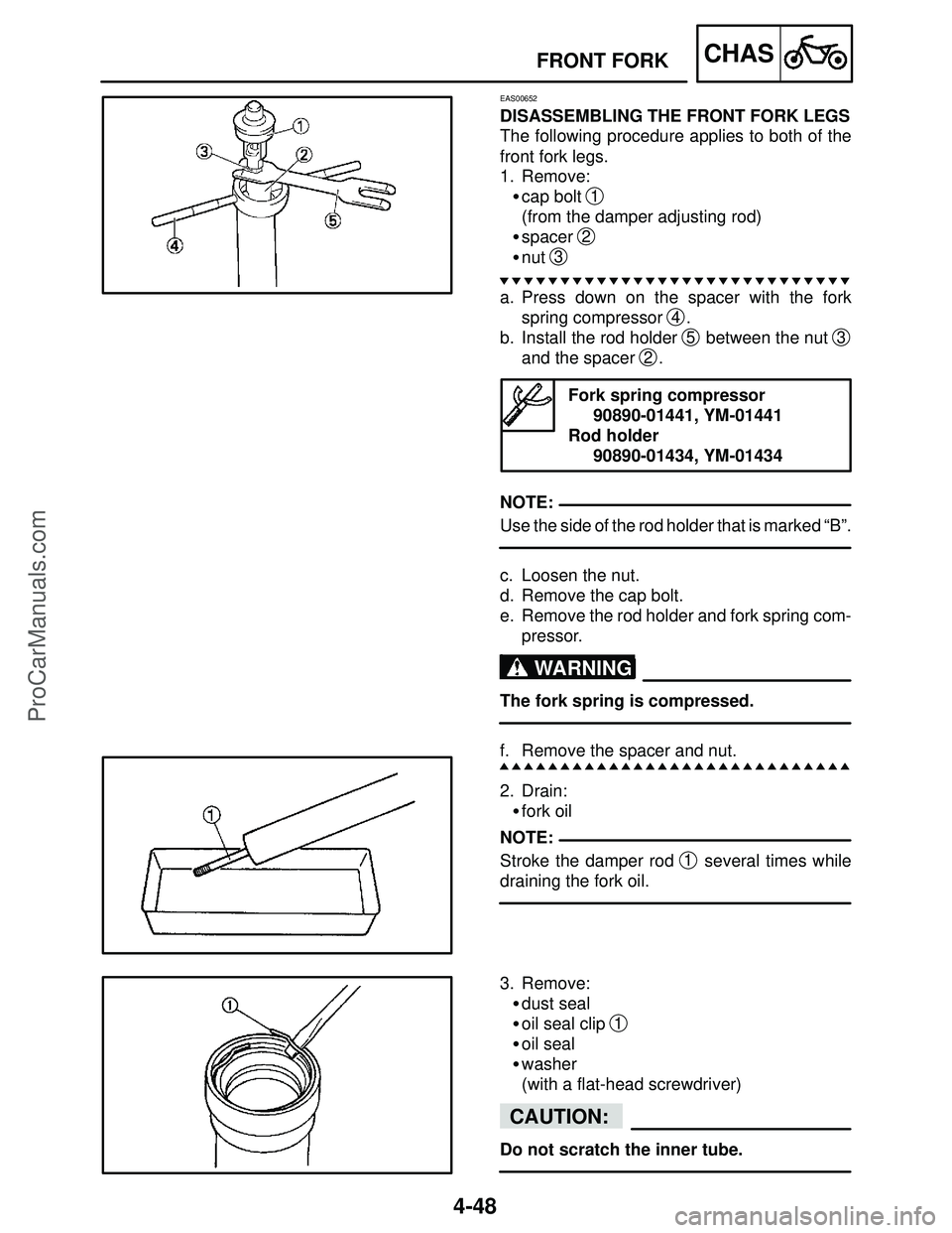
EAS00652
DISASSEMBLING THE FRONT FORK LEGS
The following procedure applies to both of the
front fork legs.
1. Remove:
�cap bolt
1
(from the damper adjusting rod)
�spacer
2
�nut 3
a. Press down on the spacer with the fork
spring compressor
4.
b. Install the rod holder
5 between the nut 3
and the spacer 2.
Fork spring compressor
90890-01441, YM-01441
Rod holder
90890-01434, YM-01434
Use the side of the rod holder that is marked “B”.
c. Loosen the nut.
d. Remove the cap bolt.
e. Remove the rod holder and fork spring com-
pressor.
The fork spring is compressed.
f. Remove the spacer and nut.
2. Drain:
�fork oil
Stroke the damper rod
1 several times while
draining the fork oil.
3. Remove:
�dust seal
�oil seal clip
1
�oil seal
�washer
(with a flat-head screwdriver)
Do not scratch the inner tube.
ProCarManuals.com
Page 260 of 457
5-38
STARTER CLUTCH AND GENERATORENG
NOTE: REMOVING THE GENERATOR
1. Remove:
�rider seat
�fuel tank
Refer to “SEATS” and “FUEL TANK” in chapter
3.
2. Remove:
�left side cowling
�bottom cowlings
Refer to “COWLINGS” in chapter 3.
3. Drain:
�engine oil
Refer to “CHANGING THE ENGINE OIL” in
chapter 3.
4. Remove:
�plug
�generator rotor cover
1
�While pushing generator rotor, remove the
generator rotor cover.
�Loosen each bolt 1 / 4 of a turn a time, in stages
and in a crisscross pattern.
�After all of the bolts are fully loosened, remove
them.
5. Remove:
�generator rotor and starter clutch assembly
1.
6. Remove:
�idler gear shaft bolt
1
�idler shaft
�idler gear
2
ProCarManuals.com
Page 266 of 457

10 Nm (1.0 m�kg, 7.2 ft�lb)
REMOVING THE CRANKSHAFT POSITION
SENSOR
1. Remove:
�rider seat
�fuel tank
Refer to “SEATS” and “")
5-44
CRANKSHAFT POSITION SENSORENG
NOTE:
12 Nm (1.2 m�kg, 8.7 ft�lb)
10 Nm (1.0 m�kg, 7.2 ft�lb)
REMOVING THE CRANKSHAFT POSITION
SENSOR
1. Remove:
�rider seat
�fuel tank
Refer to “SEATS” and “FUEL TANK” in chap-
ter 3.
2. Remove:
�right side cowling
�bottom cowlings
Refer to “COWLINGS” in chapter 3.
3. Drain:
�engine oil
Refer to “CHANGING THE ENGINE OIL” in
chapter 3.
4. Disconnect:
�crankshaft position sensor lead coupler
5. Remove:
�crankshaft position sensor
�O-ring
�pickup rotor cover
1
Loosen each bolt 1 / 4 of a turn a time, in stages
and in a crisscross pattern.
After all of the bolts are fully loosened, remove
them.
INSTALLING THE CRANKSHAFT POSITION
SENSOR
1. Install:
�gasket
New
�pickup rotor cover
1
�O-ring New
�crankshaft position sensor
LOCTITE
2. Connect:
�crankshaft position sensor lead coupler
3. Fill:
�engine oil
Refer to “CHANGING THE ENGINE OIL” in
chapter 3.
4. Install:
�right side cowling
�bottom cowlings
Refer to “COWLINGS” in chapter 3.
ProCarManuals.com
Page 293 of 457
5-71
OIL PAN AND OIL PUMPENG
12 Nm (1.2 m�kg, 8.7 ft�lb)
10 Nm (1.0 m�kg, 7.2 ft�lb)
43Nm (4.3 m�kg, 31 ft�lb)
WARNING
NOTE:
EAS00380
INSTALLING THE OIL PAN
1. Install:
�dowel pins
�gasket
New
�oil pan
1
�oil level switch 2
�engine oil drain bolt 3
Always use new copper washers.
�Tighten the oil pan bolts in stages and in a
crisscross pattern.
�Lubricate the oil level switch O-ring with en-
gine oil.
ProCarManuals.com