Page 196 of 506
3 - 38
INSP
ADJ
IGNITION TIMING CHECK
7. Adjust:
�Ignition timing
8. Check:
�Ignition timing
Re-check the ignition timing. Adjustment steps:
�Loosen the screws (stator) 1.
�Align the punch mark on the rotor with
punch mark on stator 2 by moving the
stator.
�Tighten the screws (stator).
T R..
Screw (stator):
8 Nm (0.8 m kg, 5.8 ft lb)
5PA30900
Page 290 of 506
4 - 47
ENG
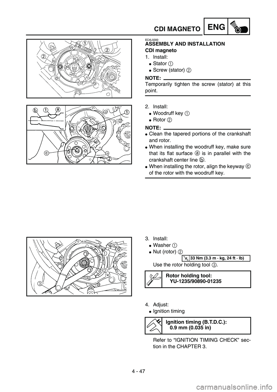
EC4L5000
ASSEMBLY AND INSTALLATION
CDI magneto
1. Install:
�Stator 1
�Screw (stator) 2
NOTE:
Temporarily tighten the screw (stator) at this
point.5PA41430
2. Install:
�Woodruff key 1
�Rotor 2
NOTE:
�Clean the tapered portions of the crankshaft
and rotor.
�When installing the woodruff key, make sure
that its flat surface a is in parallel with the
crankshaft center line b.
�When installing the rotor, align the keyway c
of the rotor with the woodruff key.
5PA41440
3. Install:
�Washer 1
�Nut (rotor) 2
Use the rotor holding tool 3.
Rotor holding tool:
YU-1235/90890-01235
5PA41450
T R..33 Nm (3.3 m · kg, 24 ft · lb)
4. Adjust:
�Ignition timing
Refer to “IGNITION TIMING CHECK” sec-
tion in the CHAPTER 3.
Ignition timing (B.T.D.C.):
0.9 mm (0.035 in)
CDI MAGNETO
Page 292 of 506
4 - 48
ENG
5. Tighten:
�Screw (stator) 1
6. Check:
�Ignition timing
Re-check the ignition timing.
5PA41460
T R..8 Nm (0.8 m · kg, 5.8 ft · lb)
7. Connect:
�CDI magneto lead 1
Refer to “CABLE ROUTING DIAGRAM”
section in the CHAPTER 2.
5PA41470
8. Install:
�Gasket (left crankcase cover)
�Left crankcase cover 1
�Screw (left crankcase cover) 2
NOTE:
Tighten the screws in stage, using a crisscross
pattern.
5PA41480
T R..5 Nm (0.5 m · kg, 3.6 ft · lb)
CDI MAGNETO
Page 450 of 506
6 - 1
–+ELECELECTRICAL COMPONENTS AND WIRING DIAGRAM
EC600000
ELECTRICAL
EC610000
ELECTRICAL COMPONENTS AND WIRING DIAGRAM
EC611000
ELECTRICAL COMPONENTS
1Engine stop switch
2Ignition coil
3CDI unit
4CDI magneto
5Spark plugCOLOR CODE
B ...................... Black
O ..................... Orange
B/R .................. Black/Red
B/W ................. Black/WhiteG/L................... Green/Blue
G/W ................. Green/White
W/L .................. White/Blue
W/R ................. White/Red
EC612000
WIRING DIAGRAM
5PA60010
5PA60020
Page 452 of 506
6 - 2
–+ELECIGNITION SYSTEM
EC620000
IGNITION SYSTEM
INSPECTION STEPS
Use the following steps for checking the possibility of the malfunctioning engine being attributable to
ignition system failure and for checking the spark plug which will not spark.
*marked: Only when the ignition checker is used.
NOTE:
�Remove the following parts before inspection.
1) Seat
2) Fuel tank
�Use the following special tools in this inspection.
Dynamic spark tester:
YM-34487
Ignition checker:
90890-06754Pocket tester:
YU-3112-C/90890-03112
Spark gap test*Clean or replace
spark plug.
Check entire ignition
system for connection.Repair or replace.
Check engine stop switch. Replace.
Check ignition coil. Primary coil Replace.
Secondary coil Replace.
Check spark plug cap. Replace.
Check CDI magneto. Pickup coil Replace.
Charging coil Replace.
Replace CDI unit.
No spark
OK
OK
OK
OK
OK
Spark
No good
No good
No good
No good
No good
No good
No good
Page 456 of 506
6 - 3
–+ELECIGNITION SYSTEM
SPARK GAP TEST
1. Disconnect the spark plug cap from spark
plug.
2. Connect the dynamic spark tester 1 (igni-
tion checker 2) as shown.
�Spark plug cap 3
�Spark plug 4
ÈFor USA and CDN
ÉExcept for USA and CDN
3. Kick the kickstarter crank.
4. Check the ignition spark gap.
5. Start engine, and increase spark gap until
misfire occurs. (for USA and CDN only)
Minimum spark gap:
6.0 mm (0.24 in)
È
5PA60030
É
5PA60040
EC624000
COUPLERS AND LEADS CONNECTION
INSPECTION
1. Check:
�Couplers and leads connection
Rust/dust/looseness/short-circuit → Repair
or replace.
ENGINE STOP SWITCH INSPECTION
1. Inspect:
�Engine stop switch conduct
No continuous while being pushed → Replace.
Continuous while being freed → Replace. Tester (+) lead
→ Black/White lead
1
Tester (–) lead
→ Black lead
2
B/W
1B
2Tester selec-
tor position
PUSH IN
Ω
× 1
FREE
5PA60050
Page 458 of 506

6 - 4
–+ELECIGNITION SYSTEM
EC626002
IGNITION COIL INSPECTION
1. Inspect:
�Primary coil resistance
Out of specification → Replace.
2. Inspect:
�Secondary coil resistance
Out of specification → Replace.
NOTE:
�Remove the spark plug cap by turning it
counterclockwise and inspect.
�Install the spark plug cap by turning it clock-
wise until it is tight.
SPARK PLUG CAP INSPECTION
1. Inspect:
�Spark plug cap
Loose connection → Tighten.
Deteriorated/Damaged → Replace.
�Spark plug cap resistance
Out of specification → Replace. Tester (+) lead
→ Orange lead
1
Tester (–) lead
→ Black lead
2
Primary coil
resistanceTester selector
position
0.18 ~ 0.28
Ω at
20 °C (68 °F)Ω
× 1
Tester (+) lead
→ Spark plug lead
1
Tester (–) lead
→ Orange lead
2
Secondary coil
resistanceTester selector
position
6.3 ~ 9.5 k
Ω at
20 °C (68 °F)k
Ω
× 1
Tester (+) lead
→
Spark plug lead terminal
1
Tester (–) lead
→ Spark plug terminal
2
Spark plug cap
resistanceTester selector
position
4 ~ 6 k
Ω at
20 °C (68 °F)k
Ω
× 1
5PA60060
5PA60070
5PA60070
5PA60070
2
1
Page 460 of 506
6 - 5
–+ELECIGNITION SYSTEM
CDI MAGNETO INSPECTION
1. Inspect:
�Pickup coil resistance
Out of specification → Replace.
Tester (+) lead
→ White/Red lead
1
Tester (–) lead
→ White/Blue lead
2
Pickup coil
resistanceTester selector
position
248 ~ 372
Ω at
20 °C (68 °F)Ω
× 100
5PA60080
2. Inspect:
�Charging coil 1 resistance
Out of specification → Replace.
3. Inspect:
�Charging coil 2 resistance
Out of specification → Replace.
EC628000
CDI UNIT INSPECTION
Check all electrical components. If no fault is
found, replace the CDI unit. Then check the
electrical components again.Tester (+) lead
→ Black/Red lead
1
Tester (–) lead
→ Green/White lead
2
Charging coil 1
resistanceTester selector
position
720 ~ 1,080
Ω
at 20 °C (68 °F)Ω
× 100
Tester (+) lead
→ Green/Blue lead
1
Tester (–) lead
→ Black lead
2
Charging coil 2
resistanceTester selector
position
44 ~ 66
Ω at
20 °C (68 °F)Ω
× 10
5PA60090
5PA60100