Page 546 of 642
5 - 56
CHASSWINGARM
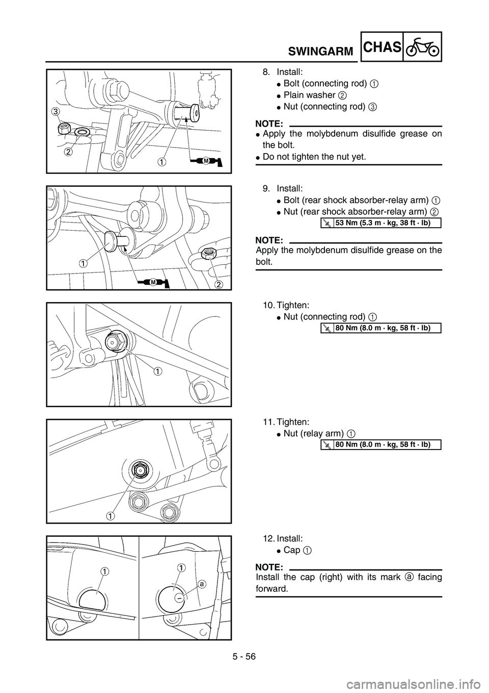
8. Install:
�Bolt (connecting rod) 1
�Plain washer 2
�Nut (connecting rod) 3
NOTE:
�Apply the molybdenum disulfide grease on
the bolt.
�Do not tighten the nut yet.
9. Install:
�Bolt (rear shock absorber-relay arm) 1
�Nut (rear shock absorber-relay arm) 2
NOTE:
Apply the molybdenum disulfide grease on the
bolt.
T R..53 Nm (5.3 m · kg, 38 ft · lb)
10. Tighten:
�Nut (connecting rod) 1
T R..80 Nm (8.0 m · kg, 58 ft · lb)
11. Tighten:
�Nut (relay arm) 1
T R..80 Nm (8.0 m · kg, 58 ft · lb)
12. Install:
�Cap 1
NOTE:
Install the cap (right) with its mark a facing
forward.
Page 550 of 642
5 - 58
CHASREAR SHOCK ABSORBER
EC580000
REAR SHOCK ABSORBER
Extent of removal:1 Rear shock absorber removal2 Rear shock absorber disassembly
Extent of removal Order Part name Q’ty Remarks
Preparation for removalREAR SHOCK ABSORBER
REMOVAL
Hold the machine by placing the
suitable stand under the engine.
WARNINGSupport the machine securely so there is nodanger of it falling over.
Seat and fitting band Refer to “SEAT, FUEL TANK AND SIDE
COVERS” section in the CHAPTER 4.
Silencer Refer to “EXHAUST PIPE AND
SILENCER” section in the CHAPTER 4.
1 Clamp (air filter joint) 1 Only loosening.
2 Rear frame 1
3 Bolt (rear shock absorber-relay
arm)1 Hold the swingarm.
4 Bolt (rear shock absorber-frame) 1
5 Rear shock absorber 1
6 Locknut 1 Only loosening.
7 Adjuster 1 Only loosening.
8 Spring guide (lower) 1
1
2
Page 552 of 642
5 - 59
CHASREAR SHOCK ABSORBER
Extent of removal Order Part name Q’ty Remarks
9 Spring guide (upper) 1
10 Spring (rear shock absorber) 1
11 Bearing 2 Refer to “REMOVAL POINTS”.
2
Page 554 of 642

5 - 60
CHAS
EC586000
HANDLING NOTE
WARNING
This shock absorber is provided with a
separate type tank filled with high-pressure
nitrogen gas. To prevent the danger of
explosion, read and understand the follow-
ing information before handling the shock
absorber.
The manufacturer can not be held respon-
sible for property damage or personal
injury that may result from improper han-
dling.
1. Never tamper or attempt to disassem-
ble the cylinder or the tank.
2. Never throw the shock absorber into
an open flame or other high heat. The
shock absorber may explode as a
result of nitrogen gas expansion and/
or damage to the hose.
3. Be careful not to damage any part of
the gas tank. A damaged gas tank will
impair the damping performance or
cause a malfunction.
4. Take care not to scratch the contact
surface of the piston rod with the cylin-
der; or oil could leak out.
5. Never attempt to remove the plug at
the bottom of the nitrogen gas tank. It
is very dangerous to remove the plug.
6. When scrapping the shock absorber,
follow the instructions on disposal.
EC587000
NOTES ON DISPOSAL (YAMAHA DEALERS
ONLY)
Before disposing the shock absorber, be sure
to extract the nitrogen gas from valve 1. Wear
eye protection to prevent eye damage from
escaping gas and/or metal chips.
WARNING
To dispose of a damaged or worn-out
shock absorber, take the unit to your
Yamaha dealer for this disposal procedure.
REAR SHOCK ABSORBER
Page 556 of 642
5 - 61
CHAS
EC583000
REMOVAL POINTS
EC583320
Bearing
1. Remove:
�Stopper ring (upper bearing) 1
NOTE:
Press in the bearing while pressing its outer
race and remove the stopper ring.
2. Remove:
�Upper bearing 1
NOTE:
Remove the bearing by pressing its outer race.
3. Remove:
�Lower bearing 1
NOTE:
Remove the bearing by pressing its outer race.
EC584000
INSPECTION
Rear shock absorber
1. Inspect:
�Damper rod 1
Bends/damage → Replace absorber
assembly.
�Shock absorber 2
Oil leaks → Replace absorber assem-
bly.
Gas leaks → Replace absorber assem-
bly.
�Spring 3
Damage → Replace spring.
Fatigue → Replace spring.
Move spring up and down.
�Spring guide 4
Wear/damage → Replace spring guide.
�Bearing 5
Free play exists/unsmooth revolution/
rust → Replace.
REAR SHOCK ABSORBER
Page 558 of 642
5 - 62
CHASREAR SHOCK ABSORBER
EC585000
ASSEMBLY AND INSTALLATION
EC585300
Bearing
1. Install:
�Upper bearing 1
NOTE:
Install the bearing parallel until the stopper ring
groove appears by pressing its outer race.
CAUTION:
Do not apply the grease on the bearing
outer race because it will wear the rear
shock absorber surface on which the bear-
ing is press fitted.
2. Install:
�Stopper ring (upper bearing) 1
NOTE:
After installing the stopper ring, push back the
bearing until it contacts the stopper ring.
New
3. Install:
�Lower bearing 1
NOTE:
Install the bearing by pressing it on the side
having the manufacture’s marks or numbers.
Installed depth of the bearing a:
4 mm (0.16 in)
EC585111
Spring (rear shock absorber)
1. Install:
�Spring 1
�Spring guide (upper) 2
�Spring guide (lower) 3
Page 560 of 642
5 - 63
CHASREAR SHOCK ABSORBER
2. Tighten:
�Adjuster 1
3. Adjust:
�Spring length (installed) a
* For EUROPE
NOTE:
The length of the spring (installed) changes
1.5 mm (0.06 in) per turn of the adjuster.
CAUTION:
Never attempt to turn the adjuster beyond
the maximum or minimum setting.
4. Tighten:
�Locknut 1
Rear shock absorber
1. Install:
�Dust seal 1
�O-ring 2
�Collar 3
NOTE:
�Apply the molybdenum disulfide grease on
the bearing.
�Apply the lithium soap base grease on the
dust seals, O-rings and collars.
Spring length (installed) a:
Standard
lengthExtent of
adjustment
248 mm (9.76 in)
*263 mm (10.35 in)240.5 ~ 258.5 mm
(9.47 ~ 10.18 in)
*255.5 ~ 273.5 mm
(10.06 ~ 10.77 in)
New
Page 562 of 642
5 - 64
CHASREAR SHOCK ABSORBER
2. Install:
�Bush 1
�Collar 2
�Dust seal 3
NOTE:
�Apply the molybdenum disulfide grease on
the bearing.
�Apply the lithium soap base grease on the
bush, collars and dust seals.
�Install the dust seals with their lips facing
outward.
3. Install:
�Rear shock absorber
4. Install:
�Bolt (rear shock absorber-frame) 1
�Nut (rear shock absorber-frame) 2
NOTE:
Apply the molybdenum disulfide grease on the
bolt.
5. Install:
�Bolt (rear shock absorber-relay arm) 1
�Nut (rear shock absorber-relay arm) 2
NOTE:
Apply the molybdenum disulfide grease on the
bolt.
T R..56 Nm (5.6 m · kg, 40 ft · lb)
T R..53 Nm (5.3 m · kg, 38 ft · lb)
6. Install:
�Rear frame 1
�Bolt [rear frame (upper)] 2
�Bolt [rear frame (lower)] 3
T R..32 Nm (3.2 m · kg, 23 ft · lb)
T R..29 Nm (2.9 m · kg, 21 ft · lb)
7. Tighten:
�Screw (air filter joint) 1
T R..3 Nm (0.3 m · kg, 2.2 ft · lb)

 1
10 Spring (rear shock absorber) 1
11 Bearing 2 Refer to “REMOVAL POINTS”.
2")


