Page 400 of 642
4 - 81
ENGENGINE REMOVAL
Extent of removal:1 Engine removal
Extent of removal Order Part name Q’ty Remarks
1 Engine skid plate (front) 1
2 Neutral switch 1
3 Oil hose 2
4 Chain cover 1
5 Nut (drive sprocket) 1
Refer to “REMOVAL POINTS”. 6 Lock washer 1
7 Drive sprocket 1
8 Clip 1
9 Bolt (brake pedal) 1
10 Brake pedal 1
11 Engine upper bracket (right) 1
12 Engine upper bracket (left) 1
13 Engine lower bracket 2
14 Engine mounting bolt 3
15 Pivot shaft 1
Refer to “REMOVAL POINTS”.
16 Engine 1
1
Page 402 of 642
4 - 82
ENGENGINE REMOVAL
EC4M3000
REMOVAL POINTS
EC4F3100
Drive sprocket
1. Remove:
�Nut (drive sprocket) 1
�Lock washer 2
NOTE:
�Straighten the lock washer tab.
�Loosen the nut while applying the rear brake.
2. Remove:
�Drive sprocket 1
�Drive chain 2
NOTE:
Remove the drive sprocket together with the
drive chain.
EC4M3301
Engine removal
1. Remove:
�Pivot shaft 1
NOTE:
If the pivot shaft is pulled all the way out, the
swingarm will come loose. If possible, insert a
shaft of similar diameter into the other side of
the swingarm to support it.
2. Remove:
�Engine 1
From right side.
NOTE:
Make sure that the couplers, hoses and cables
are disconnected.
1
Page 404 of 642
 4 - 83
ENGENGINE REMOVAL
EC4M5000
ASSEMBLY AND INSTALLATION
Engine installation
1. Install:
�Engine 1
Install the engine from right side.
�Pivot shaft 2
�Engine mounting bolt (lower) 3
�Engine lowe")
4 - 83
ENGENGINE REMOVAL
EC4M5000
ASSEMBLY AND INSTALLATION
Engine installation
1. Install:
�Engine 1
Install the engine from right side.
�Pivot shaft 2
�Engine mounting bolt (lower) 3
�Engine lower bracket 4
�Bolt (engine lower bracket) 5
�Engine mounting bolt (front) 6
�Bolt (engine guard) 7
�Engine upper bracket (right) 8
�Engine upper bracket (left) 9
�Bolt (engine upper bracket) 0
�Engine mounting bolt (upper) A
�Engine skid plate (front) B
�Bolt (engine skid plate) C
NOTE:
Apply the molybdenum disulfide grease on the
pivot shaft.
EC4M5211
Brake pedal
1. Install:
�Spring
�Brake pedal 1
�O-ring 2
�Bolt (brake pedal) 3
�Clip 4
NOTE:
�Apply the lithium soap base grease on the
bolt, O-rings and brake pedal bracket.
�Install the clip with its stopper portion a fac-
ing inward.
Drive sprocket
1. Install:
�Drive sprocket 1
�Drive chain 2
NOTE:
Install the drive sprocket together with the
drive chain.
T R..85 Nm (8.5 m · kg, 61 ft · lb)
T R..69 Nm (6.9 m · kg, 50 ft · lb)
T R..34 Nm (3.4 m · kg, 24 ft · lb)
T R..69 Nm (6.9 m · kg, 50 ft · lb)
T R..34 Nm (3.4 m · kg, 24 ft · lb)
T R..55 Nm (5.5 m · kg, 40 ft · lb)
T R..55 Nm (5.5 m · kg, 40 ft · lb)
T R..10 Nm (1.0 m · kg, 7.2 ft · lb)
New
T R..26 Nm (2.6 m · kg, 19 ft · lb)
Page 406 of 642
4 - 84
ENGENGINE REMOVAL
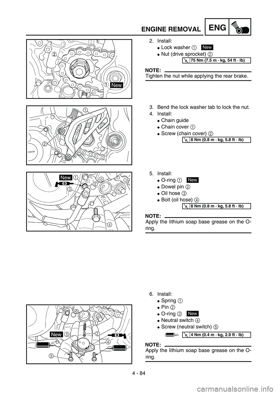
2. Install:
�Lock washer 1
�Nut (drive sprocket) 2
NOTE:
Tighten the nut while applying the rear brake.
New
T R..75 Nm (7.5 m · kg, 54 ft · lb)
3. Bend the lock washer tab to lock the nut.
4. Install:
�Chain guide
�Chain cover 1
�Screw (chain cover) 2
21T R..8 Nm (0.8 m · kg, 5.8 ft · lb)
5. Install:
�O-ring 1
�Dowel pin 2
�Oil hose 3
�Bolt (oil hose) 4
NOTE:
Apply the lithium soap base grease on the O-
ring.
6. Install:
�Spring 1
�Pin 2
�O-ring 3
�Neutral switch 4
�Screw (neutral switch) 5
NOTE:
Apply the lithium soap base grease on the O-
ring.
New
T R..8 Nm (0.8 m · kg, 5.8 ft · lb)
New
T R..4 Nm (0.4 m · kg, 2.9 ft · lb)
Page 408 of 642
4 - 85
ENGCRANKCASE AND CRANKSHAFT
CRANKCASE AND CRANKSHAFT
CRANKCASE AND CRANKSHAFT
Extent of removal:1 Crankcase separation2 Crankshaft removal
Extent of removal Order Part name Q’ty Remarks
CRANKCASE SEPARATION
Preparation for removal Engine Refer to “ENGINE REMOVAL” section.
Piston Refer to “CYLINDER AND PISTON” sec-
tion.
Balancer Refer to “BALANCER” section.
Kick axle assembly
Refer to “KICK AXLE AND SHIFT
SHAFT” section.
Segment
Stator Refer to “CDI MAGNETO” section.
1 Timing chain guide (rear) 1
2 Timing chain 1
3 Bolt (50 mm) 6
Refer to “REMOVAL POINTS”. 4 Bolt (60 mm) 2
5 Bolt (65 mm) 1
6 Bolt (75 mm) 2
7 Bolt (80 mm) 1
8 Hose guide 1
9 Clutch cable holder 1
21
Page 414 of 642
 4 - 88
ENGCRANKCASE AND CRANKSHAFT
REMOVAL POINTS
Crankcase
1. Separate:
�Crankcase (right)
�Crankcase (left)
Separation steps:
�Remove the crankcase bolts, hose guide
and clutch cable holder.
NOTE:
L")
4 - 88
ENGCRANKCASE AND CRANKSHAFT
REMOVAL POINTS
Crankcase
1. Separate:
�Crankcase (right)
�Crankcase (left)
Separation steps:
�Remove the crankcase bolts, hose guide
and clutch cable holder.
NOTE:
Loosen each bolt 1/4 of a turn at a time and
after all the bolts are loosened, remove
them.
�Remove the crankcase (right).
NOTE:
�Place the crankcase with its left side
downward and split it by inserting a screw-
driver tip into the splitting slit a in the
crankcase.
�Lift the crankcase (right) horizontally while
lightly patting the case splitting slit and
engine mounting boss using a soft ham-
mer, and leave the crankshaft and trans-
mission with the crankcase (left).
CAUTION:
Use soft hammer to tap on the case half.
Tap only on reinforced portions of case.
Do not tap on gasket mating surface.
Work slowly and carefully. Make sure the
case halves separate evenly. If one end
“hangs up”, take pressure off the push
screw, realign, and start over. If the
cases do not separate, check for a
remaining case screw or fitting. Do not
force.
�Remove the dowel pins and O-ring.
a
Page 416 of 642
4 - 89
ENGCRANKCASE AND CRANKSHAFT
Crankshaft
1. Remove:
�Crankshaft 1
Use the crankcase separating tool 2.
CAUTION:
Do not use a hammer to drive out the
crankshaft.
Crankshaft bearing
1. Remove:
�Bearing 1
NOTE:
�Remove the bearing from the crankcase by
pressing its inner race.
�Do not use the removed bearing.
Crankcase separating tool:
YU-1135-A/90890-01135
INSPECTION
Timing chain and timing chain guide
1. Inspect:
�Timing chain
Cracks/stiff → Replace the timing chain
and camshaft sprocket as a set.
2. Inspect:
�Timing chain guide
Wear/damage → Replace.
EC4N4101
Crankcase
1. Inspect:
�Contacting surface a
Scratches → Replace.
�Engine mounting boss b, crankcase
Cracks/damage → Replace.
2. Inspect:
�Bearing
Rotate inner race with a finger.
Rough spot/seizure → Replace.
3. Inspect:
�Oil seal
Wear/damage → Replace.
Page 424 of 642
4 - 93
ENGCRANKCASE AND CRANKSHAFT
5. Install:
�Dowel pin 1
�O-ring 2
�Crankcase (right)
To crankcase (left).
NOTE:
�Fit the crankcase (right) onto the crankcase
(left). Tap lightly on the case with soft ham-
mer.
�When installing the crankcase, the connect-
ing rod should be positioned at TDC (top
dead center).
New
6. Tighten:
�Hose guide 1
�Clutch cable holder 2
�Bolt (crankcase)
NOTE:
Tighten the crankcase tightening bolts in
stage, using a crisscross pattern.
7. Install:
�Oil delivery pipe 2
�O-ring
�Bolt (oil delivery pipe 2)
8. Install:
�Timing chain
�Timing chain guide (rear)
�Bolt (timing chain guide)
9. Remove:
�Sealant
Forced out on the cylinder mating surface.
10. Apply:
�Engine oil
To the crank pin, bearing and oil deliv-
ery hole.
11. Check:
�Crankshaft and transmission operation.
Unsmooth operation → Repair.
T R..12 Nm (1.2 m · kg, 8.7 ft · lb)
New
T R..10 Nm (1.0 m · kg, 7.2 ft · lb)
T R..10 Nm (1.0 m · kg, 7.2 ft · lb)
 4 - 81
ENGENGINE REMOVAL
Extent of removal:1 Engine removal
Extent of removal Order Part name Q’ty Remarks
1 Engine skid plate (front) 1
2 Neutral switch 1
3 Oil hose 2
4 Chain cover 1
5 Nut (drive")

 4 - 85
ENGCRANKCASE AND CRANKSHAFT
CRANKCASE AND CRANKSHAFT
CRANKCASE AND CRANKSHAFT
Extent of removal:1 Crankcase separation2 Crankshaft removal
Extent of removal Order Part name Q’ty Remarks
CRANK")

