Page 396 of 568
5-18
CHASFRONT BRAKE AND REAR BRAKE
3. Install:
9Brake hose holder 1
9Caliper 2
9Bolt (caliper) 3
NOTE:
Fit the brake hose holder cut aover the projec-
tion bon the front fork and clamp the brake
hose.
4. Tighten:
9Pad pin 4
5. Install:
9Pad pin plug 5
EC5A5121
Rear caliper
1. Install:
9Pad support 1
9Brake pad 2
9Pad pin 3
NOTE:
9Install the brake pads with their projections
ainto the caliper recesses b.
9Temporarily tighten the pad pin at this point.
2. Install:
9Copper washer 1
9Union bolt 2
w
Always use new copper washers.
cC
Install the brake hose so that its pipe por-
tion a a
directs as shown and lightly touch-
es the projection b b
on the caliper.
30 Nm (3.0 m•kg, 22 ft•lb)
23 Nm (2.3 m•kg, 17 ft•lb)
18 Nm (1.8 m•kg, 13 ft•lb)
3 Nm (0.3 m•kg, 2.2 ft•lb)
5XE-9-30-5A 4/28/03 6:06 PM Page 36
Page 412 of 568
5-26
CHASFRONT FORK
Extent of removal Order Part name Q’ty Remarks
FRONT FORK REMOVAL
Preparation for
Hold the machine by placing the
removalsuitable stand under the engine.
Front wheel Refer to “FRONT WHEEL AND
REAR WHEEL”section.
Front caliper Refer to “FRONT BRAKE AND
REAR BRAKE”section.
Number plate
1 Protector 1
2 Brake hose holder 2
3 Pinch bolt (handle crown) 2 Only loosening.
4 Cap bolt 1
Loosen when disassembling the front fork.
5 Pinch bolt (under bracket) 2 Only loosening.
6 Front fork 1
1
w
Support the machine securely so there is no dan-
ger of it falling over.
Extent of removal:1Front fork removal
10 Nm (1.0 m•kg, 7.2 ft•lb)
10 Nm (1.0 m•kg, 7.2 ft•lb)
10 Nm (1.0 m•kg, 7.2 ft•lb)
20 Nm (2.0 m•kg, 14 ft•lb)
23 Nm (2.3 m•kg, 17 ft•lb)
EC550000
FRONT FORK
5XE-9-30-5B 4/30/03 9:41 AM Page 2
Page 414 of 568
5-27
CHASFRONT FORK
Extent of removal Order Part name Q’ty Remarks
FRONT FORK DISASSEMBLY
1Cap bolt 1 Refer to “REMOVAL POINTS”.
2Fork spring 1 Drain the folk oil.
3Dust seal 1
4Stopper ring 1 Refer to “REMOVAL POINTS”.
5Inner tube 1
6Outer tube 1
7Piston metal 1
8Slide metal 1
9Oil seal washer 1
0Oil seal 1
qSpring guide 1
wBase valve 1 Use special tool.
eDamper rod 1 Refer to “REMOVAL POINTS”.
EC558000
FRONT FORK DISASSEMBLY
1
Extent of removal:1Oil seal removal2Damper rod removal
2
29 Nm (2.9 m•kg, 21 ft•lb)1 Nm (0.1 m•kg, 0.7 ft•lb)
30 Nm (3.0 m•kg, 22 ft•lb)
55 Nm (5.5 m•kg, 40 ft•lb)
5XE-9-30-5B 4/30/03 9:41 AM Page 4
Page 416 of 568
5-28
CHASFRONT FORK
EC556000
HANDLING NOTE
NOTE:
The front fork requires careful attention. So it is
recommended that the front fork be maintained
at the dealers.
cC
To prevent an accidental explosion of air,
the following instructions should be ob-
served:
9The front fork with a built-in piston rod
has a very sophisticated internal con-
struction and is particularly sensitive to
foreign material.
Use enough care not to allow any foreign
material to come in when the oil is re-
placed or when the front fork is disassem-
bled and reassembled.
9Before removing the cap bolts or front
forks, be sure to extract the air from the air
chamber completely.
EC553000
REMOVAL POINTSEC553160
Cap bolt
1. Remove:
9Cap bolt 1
From the outer tube.
NOTE:
Before removing the front fork from the machine,
loosen the cap bolt.
2. Remove:
9Cap bolt 1
NOTE:
Hold the locknut 2and remove the cap bolt.
5XE-9-30-5B 4/30/03 9:41 AM Page 6
Page 418 of 568
5-29
CHASFRONT FORK
EC553201
Inner tube
1. Remove:
9Dust seal 1
9Stopper ring 2
Using slotted-head screwdriver.
cC
Take care not to scratch the inner tube.
2. Remove:
9Inner tube 1
EC553311
Damper rod
1. Remove:
9Base valve 1
9Damper rod 2
NOTE:
Use a damper rod holder 3to lock the
damper rod.
EC554000
INSPECTIONEC554100
Damper rod
1. Inspect:
9Damper rod 1
Bend/Damage�Replace damper rod.
cC
The front fork with a built-in piston rod has
a very sophisticated internal construction
and is particularly sensitive to foreign ma-
terial.
Use enough care not to allow any foreign
material to come in when the oil is re-
placed or when the front fork is disassem-
bled and reassembled.
Oil seal removal steps:
9Push in slowly athe inner tube just be-
fore it bottoms out and then pull it back
quickly b.
9Repeat this step until the inner tube can
be pulled out from the outer tube.
Damper rod holder:
YM-01494/90890-01494
5XE-9-30-5B 4/30/03 9:41 AM Page 8
Page 420 of 568
5-30
CHASFRONT FORK
EC554200
Base valve
1. Inspect:
9Valve assembly 1
Wear/Damage�Replace.
9O-ring 2
Damage�Replace.
EC554400
Fork spring
1. Measure:
9Fork spring free length a
Out of specification�Replace.
EC554502
Inner tube
1. Inspect:
9Inner tube surface a
Score marks�Repair or replace.
Use #1,000 grit wet sandpaper.
Damaged oil lock piece�Replace.
9Inner tube bends
Out of specification�Replace.
Use the dial gauge 1.
NOTE:
The bending value is shown by one half of the
dial gauge reading.
w
Do not attempt to straighten a bent inner
tube as this may dangerously weaken the
tube.
EC554600
Outer tube
1. Inspect:
9Outer tube 1
Score marks/Wear/Damage�Replace.
Standard
479 mm 474 mm
(18.9 in) (18.7 in)Fork spring free length:
Inner tube bending limit:
0.2 mm (0.008 in)
5XE-9-30-5B 4/30/03 9:41 AM Page 10
Page 422 of 568
5-31
CHASFRONT FORK
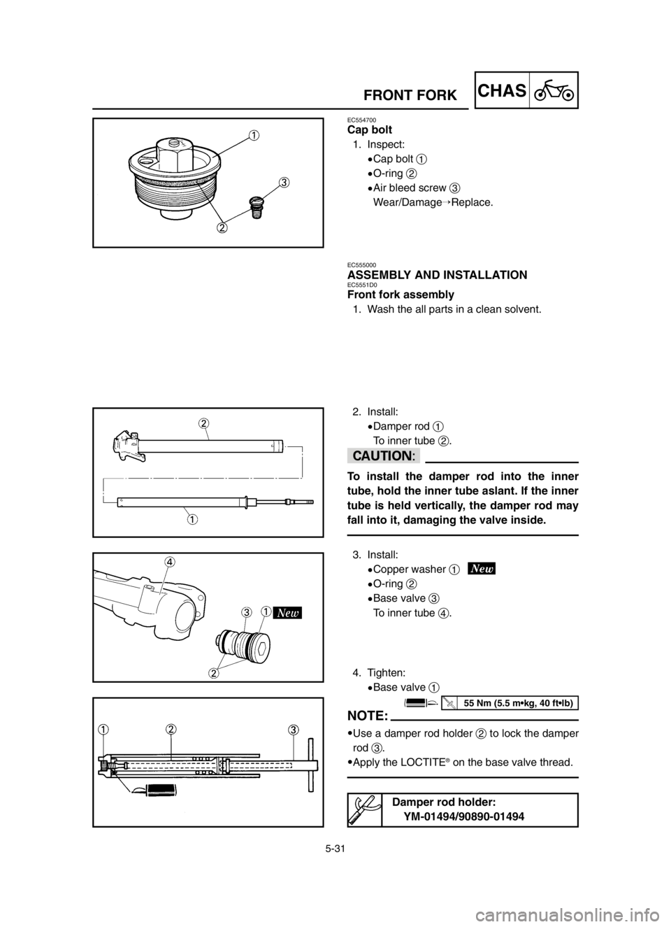
EC554700
Cap bolt
1. Inspect:
9Cap bolt 1
9O-ring 2
9Air bleed screw 3
Wear/Damage�Replace.
EC555000
ASSEMBLY AND INSTALLATIONEC5551D0
Front fork assembly
1. Wash the all parts in a clean solvent.
2. Install:
9Damper rod 1
To inner tube 2.
cC
To install the damper rod into the inner
tube, hold the inner tube aslant. If the inner
tube is held vertically, the damper rod may
fall into it, damaging the valve inside.
3. Install:
9Copper washer 1
9O-ring 2
9Base valve 3
To inner tube 4.
4. Tighten:
9Base valve 1
NOTE:
9Use a damper rod holder 2to lock the damper
rod 3.
9Apply the LOCTITE
®on the base valve thread.
Damper rod holder:
YM-01494/90890-01494
55 Nm (5.5 m•kg, 40 ft•lb)
5XE-9-30-5B 4/30/03 9:41 AM Page 12
Page 424 of 568
5-32
CHASFRONT FORK
5. Install:
9Spring guide 1
9Locknut 2
To damper rod 3.
NOTE:
9Install the spring guide with its smaller dia. end
afacing downward.
9With its thread bfacing upward, fully finger
tighten the locknut onto the damper rod.
6. Install:
9Dust seal 1
9Stopper ring 2
9Oil seal 3
9Oil seal washer 4
9Slide metal 5
To inner tube 6.
NOTE:
9Apply the fork oil on the inner tube.
9When installing the oil seal, use vinyl seat a
with fork oil applied to protect the oil seal lip.
9Install the oil seal with its manufacture's marks
or number facing the axle holder side.
9Install the oil seal washer with its projections b
facing upward.
7. Install:
9Piston metal 1
NOTE:
Install the piston metal onto the slot on inner
tube.
8. Install:
9Outer tube 1
To inner tube 2.
5XE-9-30-5B 4/30/03 9:41 AM Page 14
 3
NOTE:
Fit the brake hose holder cut aover the projec-
tion bon the front fork and clamp the brake
hos")