Page 22 of 83
Fuel tank cap
3-8TO OPEN:
Insert the key and turn it 1/4 turn clockwise. The lock will
be released and the cap can be opened.
TO CLOSE:
Push the tank cap into position with the key inserted. To
remove the key, turn it counterclockwise to the original
position.
Be sure the cap is properly installed and locked in place
before riding the motorcycle.
WARNING:
Page 25 of 83
3-11
1. Push 2. Release 3. Turn
LOCK OFF (PUSH)
Steering lock
The steering is locked when the main switch is turned to
ìLOCKî. To lock the steering, turn the handlebars all the
way to the left. With the key at ìOFFî position, push it into
the main switch and release it, turn it counterclockwise to
ìLOCKî, and remove the key. To release the lock, turn the
key to ìOFFî.
Never turn the key to “LOCK” position when the
motorcycle is moving.
WARNING:
Page 27 of 83
Insert the key and turn it 1/4 clockwise. Pull the cover
towards yourself 1 to release the fitting pin, and then, pull
it forward 2.
To reinstall, reverse the removal procedures.
3-13Remove the key nad then pull the cover towards yourself
1 to release the fitting pin, and then, pull it forward 2.
To reinstall, reverse the removal procedures.
Side covers
1. Pull 2. Pull forward1. Pull 2. Pull forward
Page 56 of 83

6-16
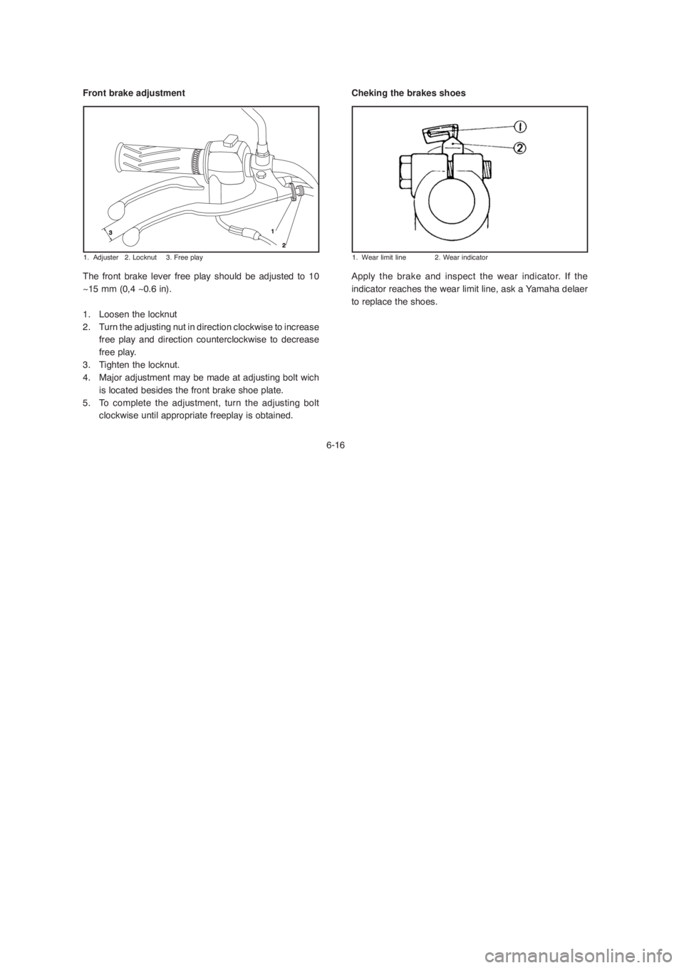
Front brake adjustment
1. Adjuster 2. Locknut 3. Free play
The front brake lever free play should be adjusted to 10
~15 mm (0,4 ~0.6 in).
1. Loosen the locknut
2. Turn the adjusting nut in direction clockwise to increase
free play and direction counterclockwise to decrease
free play.
3. Tighten the locknut.
4. Major adjustment may be made at adjusting bolt wich
is located besides the front brake shoe plate.
5. To complete the adjustment, turn the adjusting bolt
clockwise until appropriate freeplay is obtained.
Cheking the brakes shoes
1. Wear limit line 2. Wear indicator
Apply the brake and inspect the wear indicator. If the
indicator reaches the wear limit line, ask a Yamaha delaer
to replace the shoes.
Page 68 of 83
6-28
1. Screw
Headlight bulb replacement
If the headlight bulb burns out, replace the bulb as follows:
1. Remove the screws.2. Loosen the bulb connectors and remove the rubber cover.
3. Turn the bulb socket counterclockwise and remove the
bulb.
Keep flammable products and your hands away from the
bulb while it is on, as it is hot. Do not touch the bulb until it
cools down
1. Rubber cover
CAUTION:
Page 70 of 83
6-30 Turn signal bulb replacement
1. Remove the screws and the lens.
2. Push the bulb inward and turn it counterclockwise.
3. Place a new bulb in the socket.
4. Install the lens and the screws.
Do not over-tighten the screws as the lens may break.Taillight bulb replacement
1. Remove the lens.
2. Push the bulb inward and turn it counterclockwise.
3. Place a new bulb in the socket.
4. Install the lens.
CAUTION: