Page 92 of 754
SPEC
2 - 17
MAINTENANCE SPECIFICATIONS
NOTE:
- marked portion shall be checked for torque tightening after break-in or before each race. Meter cable holder and protector M5 × 0.8 2 4 0.4 2.9
Headlight stay (lower) and under bracket M8 × 1.25 2 7 0.7 5.1
Headlight body and headlight unit M6 × 1.0 2 7 0.7 5.1
Headlight mounting (left and right) M6 × 1.0 2 10 1.0 7.2
Headlight mounting (lower) M6 × 1.0 1 7 0.7 5.1
Taillight mounting M6 × 1.0 3 4 0.4 2.9
Taillight lead clamp and rear fender M4 × 1.59 2 0.5 0.05 0.36
Coolant reservoir tank mounting M6 × 1.0 2 7 0.7 5.1
Sidestand bracket mounting M10 × 1.25 2 66 6.6 48
Drive chain stopper and sidestand bracket M6 × 1.0 1 7 0.7 5.1
Sidestand mounting M8 × 1.25 1 25 2.5 18 Part to be tightened Thread size Q’tyTightening torque
Nm m·kg ft·lb
Page 160 of 754

2 - 23
SPEC
CABLE ROUTING DIAGRAM
EC240000
CABLE ROUTING DIAGRAM
1
Fuel tank breather hose
2
Clamp
3
Diode
4
Wire harness
5
Hot starter cable
6
Negative battery lead
7
Starter motor lead
8
TPS (throttle position sen-
sor) lead
9
Neutral switch lead
0
Oil hose
A
Hose holder
B
Radiator hose 4
C
Cylinder head breather hose
D
AC magneto lead
E
Radiator hose 1
F
Oil tank breather hose
G
Brake hose
H
Hose guide
I
Carburetor breather hose
J
Overflow hose
K
Coolant reservoir tank breather
hose
Å
Insert the fuel tank breather
hose into the hole in the steering
shaft cap.
ı
Fasten the diode of the wire har-
ness and rectifier/regulator lead
(at its protecting tube) to the
frame at the white tape for the
diode with a plastic locking tie
and cut off the tie end.
Ç
Fasten the wire harness, recti-
fier/regulator lead, coolant res-
ervoir hose and hot starter cable
to the frame with a plastic lock-
ing tie and cut off the tie end.
Î
Fasten the wire harness, recti-
fier/regulator lead and coolant
reservoir hose to the frame with
a plastic locking tie and cut off
the tie end.
‰
Fasten the wire harness to the
frame at its white tape with a
plastic locking tie and cut off the
tie end.
Page 164 of 754

4Throttle cable (pull)
5Ignition coil
6Negative battery lead
7Starter motor lead
8Coolant reservoir tank
brea")
2 - 25
SPECCABLE ROUTING DIAGRAM
1Hot starter cable
2Clutch cable
3Throttle cable (return)
4Throttle cable (pull)
5Ignition coil
6Negative battery lead
7Starter motor lead
8Coolant reservoir tank
breather hose
9Rectifier/regulator
0Cable holder
ACoolant reservoir hose
BRectifier/regulator lead
CClamp
DCDI unit lead
ECDI unit
FCDI unit band
GCDI unit stay (frame)
HCable bracketÅPass the throttle cables, clutch
cable and hot starter cable through
the cable guides.
ıPass the throttle cables, clutch
cable and hot starter cable between
the radiator and frame, then over
the middle radiator mounting boss.
ÇPass the throttle cables and clutch
cable on the outside of the ignition
coil.
ÎPass the carburetor breather hose
(throttle cable cover) through the
hose holder.
‰Fasten the coolant reservoir tank
breather hose and carburetor
breather hoses together with a
plastic locking tie.ÏFasten the grommet of the clutch
cable with the cable holder.
ÌFasten the rectifier/regulator lead to
the frame with a plastic locking tie
and cut off the tie end.
ÓFasten the CDI unit lead to the
frame with a plastic locking tie ends
at the lower of the frame and cut off
the tie end.
ÈInsert the CDI unit band over the
CDI unit stay (frame) as far as pos-
sible.
ÔFasten the starter motor lead and
negative battery lead to the cable
bracket in its slot with a plastic lock-
ing tie and cut off the tie end.
Do not allow the rectifier/regulator
lead to slacken.
Page 168 of 754
2 - 27
SPECCABLE ROUTING DIAGRAM
1Starter motor lead
2Negative battery lead
3Wire harness
4Clamp
5Taillight lead
6Coolant reservoir tank
breather hose
7Coolant reservoir hose
8Positive battery lead
9Starting circuit cut-off
relay
0BatteryÅPosition the starter motor lead,
negative battery lead and wire
harness in the tank damper slit.
ıFasten the wire harness to the
frame with a plastic locking tie and
cut off the tie end.
ÇDo not allow the taillight lead to
slacken.
ÎPass the starter motor lead and
negative battery lead over the car-
buretor.
‰Fasten the coolant reservoir tank
breather hose and coolant reser-
voir hose to the frame with a plas-
tic band.ÏPass the coolant reservoir hose
on the outside of the coolant res-
ervoir tank breather hose.
Page 190 of 754
3 - 6
INSP
ADJ
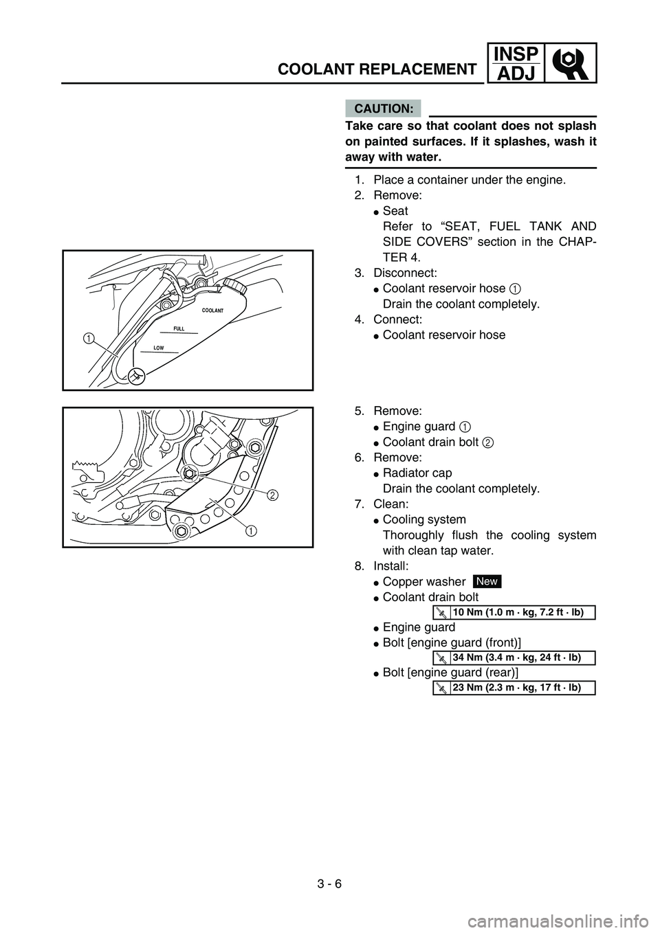
COOLANT REPLACEMENT
CAUTION:
Take care so that coolant does not splash
on painted surfaces. If it splashes, wash it
away with water.
1. Place a container under the engine.
2. Remove:
�Seat
Refer to “SEAT, FUEL TANK AND
SIDE COVERS” section in the CHAP-
TER 4.
3. Disconnect:
�Coolant reservoir hose 1
Drain the coolant completely.
4. Connect:
�Coolant reservoir hoseLOWFULLCOOLANT1
5. Remove:
�Engine guard 1
�Coolant drain bolt 2
6. Remove:
�Radiator cap
Drain the coolant completely.
7. Clean:
�Cooling system
Thoroughly flush the cooling system
with clean tap water.
8. Install:
�Copper washer
�Coolant drain bolt
�Engine guard
�Bolt [engine guard (front)]
�Bolt [engine guard (rear)]
New
T R..10 Nm (1.0 m · kg, 7.2 ft · lb)
T R..34 Nm (3.4 m · kg, 24 ft · lb)
T R..23 Nm (2.3 m · kg, 17 ft · lb)
Page 192 of 754
3 - 7
INSP
ADJ
COOLANT REPLACEMENT
9. Fill:
�Radiator
�Engine
To specified level.
CAUTION:
�Do not mix more than one type of ethyl-
ene glycol antifreeze containing corro-
sion inhibitors for aluminum engine.
�Do not use water containing impurities or oil.
Recommended coolant:
High quality ethylene glycol
anti-freeze containing
anti-corrosion for
aluminum engine
Coolant 1 and water
(soft water) 2 mixing ratio:
50%/50%
Coolant capacity:
1.25 L (1.10 Imp qt, 1.32 US qt)
Handling notes of coolant:
The coolant is harmful so it should be han-
dled with special care.
WARNING
�When coolant splashes to your eye.
Thoroughly wash your eye with water
and see your doctor.
�When coolant splashes to your clothes.
Quickly wash it away with water and
then with soap.
�When coolant is swallowed.
Quickly make him vomit and take him
to a doctor.
10. Install:
�Radiator cap
11. Fill:
�Coolant reservoir tank
Midway a between maximum and min-
imum marks on the tank.
LOWFULLCOOLANTa
Page 194 of 754
3 - 8
INSP
ADJRADIATOR CAP INSPECTION/
RADIATOR CAP OPENING PRESSURE INSPECTION
12. Install:
�Coolant reservoir cap
13. Start the engine and let it warm up for
several minutes.
14. Turn off the engine and inspect the cool-
ant level.
Refer to “COOLANT LEVEL INSPEC-
TION” section.
NOTE:
Before checking the coolant level wait a few
minutes until the coolant settles.
EC355000
RADIATOR CAP INSPECTION
1. Inspect:
�Seal (radiator cap) 1
�Valve and valve seat 2
Crack/damage → Replace.
Exist fur deposits 3 → Clean or
replace.
EC356001
RADIATOR CAP OPENING PRESSURE
INSPECTION
1. Attach:
�Radiator cap tester 1 and adapter 2
NOTE:
Apply water on the radiator cap seal.
3Radiator cap
2. Apply the specified pressure.
Radiator cap tester:
YU-24460-01/90890-01325
Adapter:
YU-33984/90890-01352
Radiator cap opening pressure:
110 kPa (1.1 kg/cm2, 15.6 psi)
Page 310 of 754
4 - 5
ENG
RADIATOR
EC450001
RADIATOR
Extent of removal:
1
Radiator removal
2
Coolant reservoir removal
Extent of removal Order Part name Q’ty Remarks
RADIATOR REMOVAL
Preparation for removal Drain the coolant. Refer to “COOLANT REPLACEMENT”
section in the CHAPTER 3.
Seat, fuel tank and side cover Refer to “SEAT, FUEL TANK AND SIDE
COVERS” section.
Exhaust pipe Refer to “EXHAUST PIPE AND
SILENCER” section.
1 Engine guard 1
2 Panel 2
3 Clamp 8
4 Radiator (right) 1
5 Hose 2 1
6 Hose 3 1
7 Hose 4 1
8 Pipe 2/O-ring 1/1
9 Radiator breather hose 1
10 Radiator (left) 1
11 Hose 1 1
12 Pipe 1/O-ring 1/1
13 Coolant reservoir hose 1
14 Coolant reservoir tank 1
1
2