Page 442 of 754
4 - 71
ENGKICK AXLE AND SHIFT SHAFT
REMOVAL POINTS
EC4B3101
Kick axle assembly
1. Remove:
�Kick axle assembly 1
NOTE:
Unhook the torsion spring 2 from the hole a
in the crankcase.
EC4C3101
Shift guide and shift lever assembly
1. Remove:
�Bolt (shift guide)
�Shift guide 1
�Shift lever assembly 2
NOTE:
The shift lever assembly is disassembled at
the same time as the shift guide.
EC4N3100
Segment
1. Remove:
�Bolt (segment) 1
�Segment 2
NOTE:
Turn the segment counterclockwise until it
stops and loosen the bolt.
INSPECTION
EC4C4200
Kick axle and ratchet wheel
1. Check:
�Ratchet wheel 1 smooth movement
Unsmooth movement → Replace.
�Kick axle 2
Wear/damage → Replace.
�Spring 3
Broken → Replace.
EC4C4300
Kick gear, kick idle gear and ratchet wheel
1. Inspect:
�Kick gear 1
�Kick idle gear 2
�Ratchet wheel 3
�Gear teeth a
�Ratchet teeth b
Wear/damage → Replace.
Page 450 of 754
4 - 75
ENGKICK AXLE AND SHIFT SHAFT
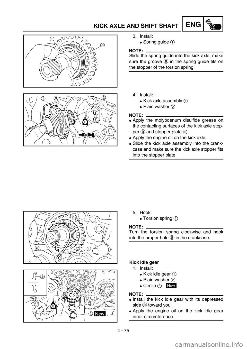
3. Install:
�Spring guide 1
NOTE:
Slide the spring guide into the kick axle, make
sure the groove a in the spring guide fits on
the stopper of the torsion spring.
4. Install:
�Kick axle assembly 1
�Plain washer 2
NOTE:
�Apply the molybdenum disulfide grease on
the contacting surfaces of the kick axle stop-
per a and stopper plate 3.
�Apply the engine oil on the kick axle.
�Slide the kick axle assembly into the crank-
case and make sure the kick axle stopper fits
into the stopper plate.
5. Hook:
�Torsion spring 1
NOTE:
Turn the torsion spring clockwise and hook
into the proper hole a in the crankcase.
Kick idle gear
1. Install:
�Kick idle gear 1
�Plain washer 2
�Circlip 3
NOTE:
�Install the kick idle gear with its depressed
side a toward you.
�Apply the engine oil on the kick idle gear
inner circumference.
New
Page 452 of 754
4 - 76
ENGAC MAGNETO AND STARTER CLUTCH
AC MAGNETO AND STARTER CLUTCH
Extent of removal:1 Starter clutch/wheel gear removal2 Rotor removal
3 Pickup coil/stator removal
Extent of removal Order Part name Q’ty Remarks
AC MAGNETO AND STATOR
REMOVAL
Preparation for removal Drain the engine oil. Refer to “ENGINE OIL REPLACEMENT”
section in the CHAPTER 3.
Seat and fuel tank Refer to “SEAT, FUEL TANK AND SIDE
COVERS” section.
Bolt [radiator (left)]
Disconnect the AC magneto lead.Refer to “RADIATOR” section.
1 Shift pedal 1
2 Engine guard (left) 1
3 Cover (torque limiter) 1
4 Torque limiter 1 Do not disassemble.
5 Crankcase cover (left) 1
6Gasket
1
31
Page 460 of 754
4 - 80
ENGAC MAGNETO AND STARTER CLUTCH
2. Install:
�Holder 1
�Bolt 2
NOTE:
�Pass the pick-up coil lead 3 and AC mag-
neto lead 4 under the holder as shown.
�Take care not to catch the AC magneto lead
between crankcase cover ribs.
�Apply the sealant to the grommet of the AC
magneto lead.
Quick gasket:
ACC-QUICK-GS-KT
YAMAHA Bond No. 1215:
90890-85505
T R..7 Nm (0.7 m · kg, 5.1 ft · lb)
3. Install:
�Starter clutch drive gear 1
�Starter clutch 2
NOTE:
Apply the engine oil on the starter clutch drive
gear inner circumference.
4. Install:
�Woodruff key 1
�Rotor 2
NOTE:
�Clean the tapered portions of the crankshaft
and rotor.
�When installing the woodruff key, make sure
that its flat surface a is in parallel with the
crankshaft center line b.
�When installing the rotor, align the keyway c
of the rotor with the woodruff key.
c
2 1 1
ba
Page 462 of 754
4 - 81
ENG
5. Install:
�Bolt (starter clutch) 1
�Plain washer (rotor)
�Nut (rotor) 2
Use the sheave holder 3.
NOTE:
Tighten the rotor nut to 65 Nm (6.5 m·kg,
47 ft·lb), loosen and retighten the rotor nut to
65 Nm (6.5 m·kg, 47 ft·lb).
Sheave holder:
YS-1880-A/90890-01701
1
1
3
2
T R..16 Nm (1.6 m · kg, 11 ft · lb)
T R..65 Nm (6.5 m · kg, 47 ft · lb)
6. Install:
�Shaft 1
�Bearing 2
�Idle gear 2 3
NOTE:
Apply the engine oil on the shaft, bearing and
idle gear inner circumference.
7. Install:
�Dowel pin
�Gasket [crankcase cover (left)]
�Crankcase cover (left) 1
�Bolt [crankcase cover (left)]
NOTE:
Tighten the bolts in stage, using a crisscross
pattern.
New
T R..10 Nm (1.0 m · kg, 7.2 ft · lb)
8. Install:
�Plain washer
�Torque limiter 1
�Plain washer
NOTE:
Apply the engine oil to the shaft and plain
washers.1
AC MAGNETO AND STARTER CLUTCH
Page 468 of 754
4 - 84
ENGENGINE REMOVAL
Extent of removal:1 Engine removal
Extent of removal Order Part name Q’ty Remarks
Crankcase cover (left) Refer to “AC MAGNETO AND
STARTER CLUTCH” section for remov-
ing the starter motor lead.
Disconnect the starter motor
lead.Refer to “ELECTRIC STARTING SYS-
TEM” section in the CHAPTER 6.
Negative battery lead Disconnect at the starter motor side.
1 Engine skid plate (front) 1
2 Neutral switch 1
3 Oil hose 2
4 Chain cover 1
5 Nut (drive sprocket) 1
Refer to “REMOVAL POINTS”. 6 Lock washer 1
7 Drive sprocket 1
8 Clip 1
9 Bolt (brake pedal) 1
10 Brake pedal 1
1
Page 478 of 754
4 - 89
ENGCRANKCASE AND CRANKSHAFT
CRANKCASE AND CRANKSHAFT
CRANKCASE AND CRANKSHAFT
Extent of removal:1 Crankcase separation2 Crankshaft removal
Extent of removal Order Part name Q’ty Remarks
CRANKCASE SEPARATION
Preparation for removal Engine Refer to “ENGINE REMOVAL” section.
Piston Refer to “CYLINDER AND PISTON” sec-
tion.
Balancer Refer to “BALANCER” section.
Kick axle assembly
Refer to “KICK AXLE AND SHIFT
SHAFT” section.
Segment
Stator Refer to “AC MAGNETO AND
STARTER CLUTCH” section.
1 Timing chain guide (rear) 1
2 Timing chain 1
3 Bolt (50 mm) 6
Refer to “REMOVAL POINTS”. 4 Bolt (60 mm) 3
5 Bolt (75 mm) 3
6 Hose guide 1
7 Clutch cable holder 1
8 Crankcase (right) 1
9 Crankcase (left) 1
21
Page 480 of 754
4 - 90
ENGCRANKCASE AND CRANKSHAFT
Extent of removal Order Part name Q’ty Remarks
10 Oil strainer 1
11 Oil delivery pipe 2 1
12 Crankshaft 1 Use special tool.
Refer to “REMOVAL POINTS”.
2


 Refer to “AC MAGNETO AND
STARTER CLUTCH” section for remov-
ing")

