2004 YAMAHA WOLVERINE 350 ABS
[x] Cancel search: ABSPage 16 of 396

EBU00015
1-CONTENTS
LOCATION OF THE WARNING AND
SPECIFICATION LABELS ...................... 1-1
SAFETY INFORMATION ......................... 2-1
DESCRIPTION AND MACHINE
IDENTIFICATION ................................... 3-1
Identification number records ............... 3-3
Key identification number ..................... 3-5
Vehicle identification number ............... 3-7
Model label ........................................... 3-9
CONTROL FUNCTIONS ........................ 4-1
Main switch........................................... 4-1
Indicator and warning lights.................. 4-3
Speedometer ...................................... 4-11
Handlebar switches ............................ 4-13
Throttle lever ...................................... 4-19
Speed limiter ...................................... 4-21
Front brake lever ................................ 4-23
Brake pedal and rear brake lever ....... 4-25
Parking brake ..................................... 4-27
Drive select lever ................................ 4-29
Recoil starter ...................................... 4-31
1234
Fuel tank cap ..................................... 4-31
Fuel cock............................................ 4-33
Starter (choke) .................................. 4-35
Seat.................................................... 4-37
Storage box........................................ 4-39
Front carrier ....................................... 4-41
Rear carrier ........................................ 4-41
Front shock absorber adjustment ...... 4-43
Rear shock absorber adjustment ....... 4-45
PRE-OPERATION CHECKS .................. 5-1
Front and rear brakes .......................... 5-5
Fuel ...................................................... 5-9
Engine oil ........................................... 5-13
Final gear oil ...................................... 5-15
Differential gear oil ............................. 5-17
Throttle lever ...................................... 5-17
Fittings and fasteners......................... 5-19
Lights ................................................. 5-19
Switches............................................. 5-19
Tires ................................................... 5-21
How to measure tire pressure ............ 5-25
Tire wear limit..................................... 5-27
5
U5UH60.book Page 1 Wednesday, October 8, 2003 9:05 AM
Page 56 of 396

3-1
EBU00032
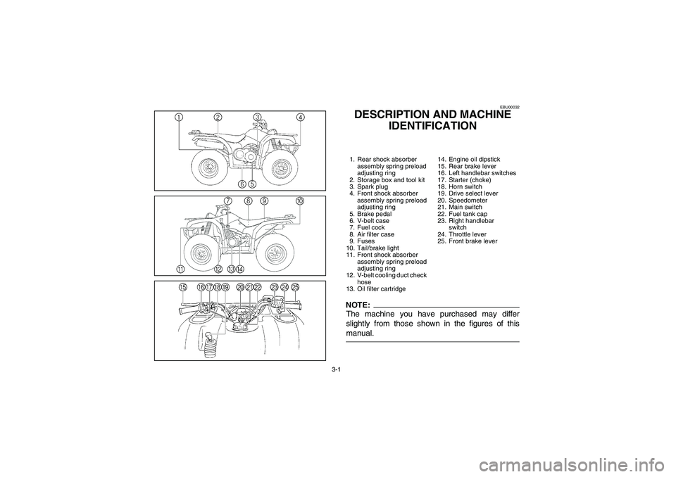
DESCRIPTION AND MACHINE
IDENTIFICATION1. Rear shock absorber
assembly spring preload
adjusting ring
2. Storage box and tool kit
3. Spark plug
4. Front shock absorber
assembly spring preload
adjusting ring
5. Brake pedal
6. V-belt case
7. Fuel cock
8. Air filter case
9. Fuses
10. Tail/brake light
11. Front shock absorber
assembly spring preload
adjusting ring
12. V-belt cooling duct check
hose
13. Oil filter cartridge14. Engine oil dipstick
15. Rear brake lever
16. Left handlebar switches
17. Starter (choke)
18. Horn switch
19. Drive select lever
20. Speedometer
21. Main switch
22. Fuel tank cap
23. Right handlebar
switch
24. Throttle lever
25. Front brake leverNOTE:The machine you have purchased may differ
slightly from those shown in the figures of this
manual.
U5UH60.book Page 1 Wednesday, October 8, 2003 9:05 AM
Page 108 of 396

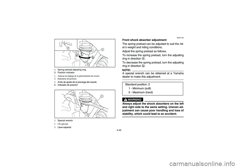
4-43 1. Spring preload adjusting ring
2. Position indicator
1. Anneau de réglage de la précontrainte de ressort
2. Indicateur de position
1. Anillo de ajuste de la precarga del resorte
2. Indicador de posición
1. Special wrench
1. Clé spéciale
1. Llave especial
EBU01163
Front shock absorber adjustment
The spring preload can be adjusted to suit the rid-
er’s weight and riding conditions.
Adjust the spring preload as follows.
To increase the spring preload, turn the adjusting
ring in direction
a.
To decrease the spring preload, turn the adjusting
ring in direction
b.NOTE:_ A special wrench can be obtained at a Yamaha
dealer to make this adjustment. _
WARNING
_ Always adjust the shock absorbers on the left
and right side to the same setting. Uneven ad-
justment can cause poor handling and loss of
stability, which could lead to an accident. _
Standard position: 2
1 - Minimum (soft)
5 - Maximum (hard)
U5UH60.book Page 43 Wednesday, October 8, 2003 9:05 AM
Page 110 of 396

4-45 1. Spring preload adjusting ring
2. Position indicator
1. Anneau de réglage de la précontrainte de ressort
2. Indicateur de position
1. Anillo de ajuste de la precarga del resorte
2. Indicador de posición
1. Special wrench
1. Clé spéciale
1. Llave especial
EBU01103
Rear shock absorber adjustment
The spring preload can be adjusted to suit the rid-
er’s weight and riding conditions.
Adjust the spring preload as follows:
To increase the spring preload, turn the adjusting
ring in direction
a.
To decrease the spring preload, turn the adjusting
ring in direction
b.NOTE:_ A special wrench can be obtained at a Yamaha
dealer to make this adjustment. _
Standard position: 2
1 - Minimum (soft)
5 - Maximum (hard)
U5UH60.book Page 45 Wednesday, October 8, 2003 9:05 AM
Page 183 of 396

7-14
Ne pas conduire après avoir absorbé de l’alcool, cer-
tains médicaments ou de la drogue.
L’alcool, certains médicaments et les drogues diminuent
les facultés du conducteur.
AVERTISSEMENT
_ Ne jamais consommer d’alcool, certains médicaments
ou des drogues avant ou pendant la conduite de ce
VTT. _Contrôles avant le démarrage
Toujours effectuer les contrôles avant le démarrage dé-
crits à la page 5-1 avant de démarrer, afin de garantir la
conduite en toute sécurité et pour maintenir le véhicule en
bon état.
AVERTISSEMENT
_ Toujours effectuer ces contrôles avant chaque départ
afin de s’assurer que le VTT puisse être utilisé en tou-
te sécurité. Toujours respecter les procédés et inter-
valles de contrôle et d’entretien repris dans ce ma-
nuel. Omettre le contrôle du VTT avant le départ ou
ne pas veiller à son entretien correct augmente les ris-
ques d’accident ou d’endommagement. _
No conduzca después de haber consumido alco-
hol o drogas.
La capacidad de conducción del piloto disminuye de-
bido a la influencia de las drogas o el alcohol.
ADVERTENCIA
_ No consuma alcohol o drogas antes o durante la
conducción de este ATV. _Comprobaciones previas a la conducción
Para la debida seguridad y el cuidado correcto del
ATV, efectúe siempre las comprobaciones previas a
la conducción que se enumeran en la página 5-1.
ADVERTENCIA
_ Inspeccione siempre el ATV cada vez que vaya a
utilizarse, para asegurarse de que está en condi-
ciones de funcionar sin peligro. Siga siempre los
procedimientos y programas de inspección y
mantenimiento descritos en este Manual del Pro-
pietario. Si no se inspecciona el ATV antes de
conducirlo ni se realizan las labores de manteni-
miento necesarias, aumentarán los riesgos de
sufrir un accidente o de causar daños al equipo. _
U5UH60.book Page 14 Wednesday, October 8, 2003 9:05 AM
Page 243 of 396

7-74
Le contrôle des dérapages est une technique qui s’ac-
quiert en s’entraînant. Choisir avec discernement le ter-
rain sur lequel on s’entraîne, car la stabilité et le contrôle
du véhicule seront réduits. Il convient absolument d’évi-
ter d’effectuer des manœuvres de dérapage sur des surfa-
ces extrêmement glissantes, telles que la glace ou le ver-
glas, afin de réduire le risque de perte de contrôle du
véhicule.
AVERTISSEMENT
_ Apprendre à contrôler le patinage ou le glissement en
s’exerçant à des vitesses lentes et sur une surface uni-
forme et de niveau.
Sur des surfaces extrêmement glissantes, telles que de
la glace, rouler lentement et être très prudent afin de
limiter le risque de perte de contrôle du véhicule. _
Con práctica, al cabo de algún tiempo se puede do-
minar el derrape controlado. Antes de intentar tales
maniobras hay que elegir el terreno cuidadosamen-
te, ya que al realizarlas se reducen tanto la estabili-
dad como el control. Tenga en cuenta que han de
evitarse las maniobras de derrape en superficies ex-
tremadamente resbaladizas, como por ejemplo so-
bre hielo, ya que podría perderse totalmente el con-
trol.
ADVERTENCIA
_ Aprenda a controlar con seguridad los derrapes
practicando a baja velocidad en terreno liso y ho-
rizontal.
En superficies extremadamente resbaladizas, ta-
les como hielo, circule despacio y sea extrema-
damente precavido para evitar el riesgo de per-
der el control a causa de un patinazo o un
derrape. _
U5UH60.book Page 74 Wednesday, October 8, 2003 9:05 AM
Page 354 of 396

8-105 1. Headlight bulb holder tab (× 2)
1. Languette de fixation d’ampoule de phare (× 2)
1. Lengüeta del portabombillas del faro (× 2)
1. Do not touch the glass part of the bulb.
1. Ne pas toucher le verre de l’ampoule.
1. No tocar la parte de cristal de la bombilla.
3. Remove the defective bulb by unhooking the
headlight bulb holder tabs.
WARNING
_ A headlight bulb is hot when it is on and imme-
diately after it is turned off. Wait for the bulb to
cool before touching or removing it. You can
be burned or a fire could start if the bulb touch-
es something flammable. _4. Insert a new headlight bulb into the bulb hold-
er, and then secure the bulb by hooking the
tabs onto the bulb.CAUTION:_ Do not touch the glass part of the headlight
bulb to keep it free from oil, otherwise the
transparency of the glass, the luminosity of the
bulb, and the bulb life will be adversely affect-
ed. Thoroughly clean off any dirt and finger-
prints on the headlight bulb using a cloth
moistened with alcohol or thinner. _5. Install the headlight bulb holder by turning it
clockwise.
6. Install the headlight bulb holder cover at the
rear of the headlight.
U5UH60.book Page 105 Wednesday, October 8, 2003 9:05 AM
Page 366 of 396

9-3
CAUTION:
Excessive water pressure may cause water
seepage and deterioration of wheel bearings,
brakes, transmission seals and electrical de-
vices. Many expensive repair bills have result-
ed from improper high pressure detergent
applications such as those available in coin-
operated car washers.4. Once the majority of the dirt has been hosed
off, wash all surfaces with warm water and
mild, detergent-type soap. An old toothbrush
or bottle brush is handy for hard-to-get-at
places.
5. Rinse the machine off immediately with clean
water and dry all surfaces with a chamois,
clean towel or soft absorbent cloth.
6. Clean the seat with a vinyl upholstery cleaner
to keep the cover pliable and glossy.
U5UH60.book Page 3 Wednesday, October 8, 2003 9:05 AM