Page 48 of 364
1 - 10
GEN
INFO
CONTROL FUNCTIONS
KICK STARTER
WARNING
Before starting the engine, be sure to shift
the transmission into neutral.
Rotate the kick starter 1 away from the
engine. Push the starter down lightly with your
foot until the gears engage, then kick smoothly
and forcefully to start the engine.
EC155001
THROTTLE GRIP
The throttle grip 1 is located on the right han-
dlebar; it accelerates or decelerates the
engine. For acceleration, turn the grip toward
you; for deceleration, turn it away from you.
1
EC156000
FRONT BRAKE LEVER
The front brake lever 1 is located on the right
handlebar. Pull it toward the handlebar to acti-
vate the front brake.
1
EC157000
REAR BRAKE PEDAL
The rear brake pedal 1 is located on the right
side of the machine. Press down on the brake
pedal to activate the rear brake.
Page 228 of 364

4 - 22
ENGCYLINDER AND PISTON
REMOVAL POINTS
Piston
1. Remove:
�Piston pin clips 1
�Piston pin 2
�Piston 3
NOTE:
�Before removing the piston pin clip, cover the
crankcase opening with a clean towel or rag
to prevent the clip from falling into the crank-
case cavity.
�Before removing each piston pin, deburr the
clip groove and pin hole area. If the piston
pin groove is deburred and the piston pin is
still difficult to remove, use the piston pin
puller set 4.
Piston pin puller set:
YU-1304/90890-01304
Piston ring
1. Remove:
�Piston rings
NOTE:
Spread the end gaps apart while at the same
time lifting the piston ring over the top of the
piston crown, as shown in the illustration.
INSPECTION
Cylinder and piston
1. Inspect:
�Cylinder and piston walls
Vertical scratches → Replace cylinder
and piston.
2. Measure:
�Piston-to-cylinder clearance
Measurement steps:
1st step:
�Measure the cylinder bore “C” with a cylin-
der bore gauge.
NOTE:
Measure the cylinder bore “C” in parallel to
and at right angles to the crankshaft. Then,
find the average of the measurements.
Page 284 of 364
4 - 50
ENGSHIFT FORK, SHIFT CAM AND TRANSMISSION
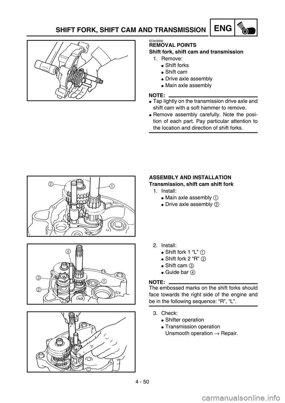
EC4H3000
REMOVAL POINTS
Shift fork, shift cam and transmission
1. Remove:
�Shift forks
�Shift cam
�Drive axle assembly
�Main axle assembly
NOTE:
�Tap lightly on the transmission drive axle and
shift cam with a soft hammer to remove.
�Remove assembly carefully. Note the posi-
tion of each part. Pay particular attention to
the location and direction of shift forks.
ASSEMBLY AND INSTALLATION
Transmission, shift cam shift fork
1. Install:
�Main axle assembly 1
�Drive axle assembly 2
2. Install:
�Shift fork 1 “L” 1
�Shift fork 2 “R” 2
�Shift cam 3
�Guide bar 4
NOTE:
The embossed marks on the shift forks should
face towards the right side of the engine and
be in the following sequence: “R”, “L”.
3. Check:
�Shifter operation
�Transmission operation
Unsmooth operation → Repair.