Page 54 of 364

1 - 13
GEN
INFO
STARTING AND OPERATION
STARTING AND OPERATION
CAUTION:
Prior to operating the machine, perform
steps listed in pre-operation check list.
WARNING
Never start your engine or let it run for any
length of time in a closed area. The exhaust
fumes are poisonous and can cause loss of
consciousness and death within a short
time. Always operate your machine in an
area with adequate ventilation.
STARTING A COLD ENGINE
TT-R90
WARNING
Before starting the engine, be sure to shift
the transmission into neutral.
1. Turn the fuel cock to “ON”.
2. Operate the starter (choke) and com-
pletely close the throttle grip.
3. Slide the “ENGINE STOP” switch to the
“”.
4. Kick the kick starter with full strength to
start the engine.
5. After the engine starts, warm up for one
or two minutes. Make sure the stater
(choke) is returned to the original position
before riding.
TT-R90E
WARNING
Before starting the engine, be sure to shift
the transmission into neutral.
NOTE:
�This model is equipped with an ignition cir-
cuit cut-off system. In case of electric start-
ing, the engine can be started only when the
transmission is in neutral.
�If the engine fails to start by pushing the start
switch, release the switch, wait a few sec-
onds, and then try again. Each starting
attempt should be as short as possible to
preserve the battery. Do not crank the
engine more than 10 seconds on any one
attempt. If the engine does not start with the
starter motor, try using the kickstarter.1. Turn the fuel cock to “ON”.
2. Turn the main switch to “ON”.
3. Shift the transmission into neutral.
4. Operate the starter (choke) and com-
pletely close the throttle grip.
5. Start the engine by pushing the start
switch or by kicking the kickstarter.
6. After the engine starts, warm up for one
or two minutes. Make sure the stater
(choke) is returned to the original position
before riding.
STARTING A WARM ENGINE
To start a warm engine, refer to the “Starting a
cold engine” section. The starter (choke)
should not be used. The throttle should be
opened slightly.
CAUTION:
See “Engine break-in Section” prior to
operating engine for the first time.
WARMING UP
To get maximum engine life, always “warm-up”
the engine before starting off. Never accelerate
hard with a cold engine! To see whether or not
the engine is warm, see if it responds to throt-
tle normally with the stater (choke) turned off.
WARNING
Before starting off, be sure to turn up or
remove the side stand.
Failure to retract the side stand completely
can result in a serious accident when you
try to turn a corner.
ENGINE BREAK-IN
Brake-in is important to better fit the moving
and sliding parts as well as the installed parts.
It is also important to accustom the rider to the
machine better.
Avoid full-throttle run on a new machine for the
first 5 hours.
After the trial run, check for loose parts, oil
leakage and other problems.
Make full inspection and adjustment especially
of slack cables and drive chain and loose
spokes.
CAUTION:
After the break-in period, check every fit-
ting and fastener for looseness.
If any loose is found, retighten it securely.
Page 136 of 364
3 - 5
INSP
ADJ
ENGINE OIL LEVEL INSPECTION
1. Start the engine, warm it up for several
minutes and wait for five minutes.
2. Place the machine on a level place and
hold it up on upright position by placing
the suitable stand under the engine.
3. Remove:
�
Dipstick
1
4. Check:
�
Oil level
Oil level should be between maximum
a
and minimum
b
marks.
Oil level is low
→
Add oil to proper
level.
NOTE:
When inspecting the oil level, do not screw the
dipstick into the oil tank. Insert the gauge
lightly.
(For USA and CDN)
CAUTION:
�
Do not add any chemical additives.
Engine oil also lubricates the clutch and
additives could cause clutch slippage.
�
Do not allow foreign material to enter the
crankcase.
Recommended oil:
At –10 ˚C (10 ˚F) or higher
Å
:
Yamalube 4 (10W-30) or SAE
10W-30 type SE/SF motor oil
At 5 ˚C (40 ˚F) or higher
ı
:
Yamalube 4 (20W-40) or SAE
20W-40 type SE/SF motor oil
010 30 50 70
90110
130
-20
-10010
20 30 40
50
Å
ı
˚C ˚F
ENGINE OIL LEVEL INSPECTION
Page 166 of 364
3 - 20
INSP
ADJ
ELECTRICAL/SPARK PLUG INSPECTION
EC370000
ELECTRICAL
EC371001
SPARK PLUG INSPECTION
1. Remove:
�Spark plug
2. Inspect:
�Electrode 1
Wear/damage → Replace.
�Insulator color 2
Normal condition is a medium to light
tan color.
Distinctly different color → Check the
engine condition.
NOTE:
When the engine runs for many hours at low
speeds, the spark plug insulator will become
sooty, even if the engine and carburetor are in
good operating condition.
3. Measure:
�Plug gap a
Use a wire gauge or thickness gauge.
Out of specification → Regap.
4. Clean the plug with a spark plug cleaner
if necessary.
Spark plug gap:
0.6 ~ 0.7 mm (0.02 ~ 0.03 in)
Standard spark plug:
CR6HSA (NGK)
U20FSR-U (DENSO)
5. Tighten:
�Spark plug
NOTE:
�Before installing a spark plug, clean the gas-
ket surface and plug surface.
�Finger-tighten a the spark plug before
torquing to specification b.
T R..13 Nm (1.3 m · kg, 9.4 ft · lb)
Page 284 of 364
4 - 50
ENGSHIFT FORK, SHIFT CAM AND TRANSMISSION
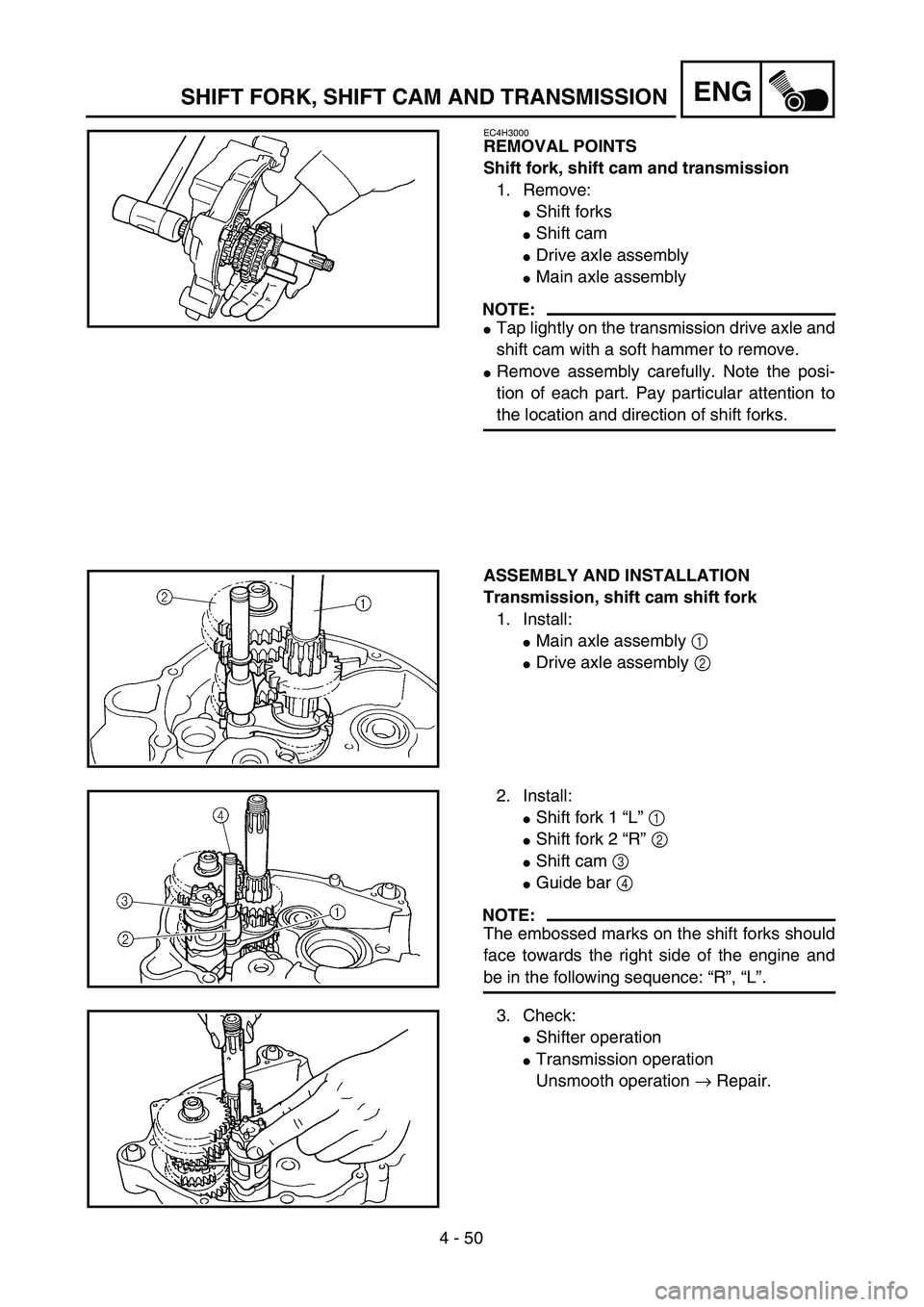
EC4H3000
REMOVAL POINTS
Shift fork, shift cam and transmission
1. Remove:
�Shift forks
�Shift cam
�Drive axle assembly
�Main axle assembly
NOTE:
�Tap lightly on the transmission drive axle and
shift cam with a soft hammer to remove.
�Remove assembly carefully. Note the posi-
tion of each part. Pay particular attention to
the location and direction of shift forks.
ASSEMBLY AND INSTALLATION
Transmission, shift cam shift fork
1. Install:
�Main axle assembly 1
�Drive axle assembly 2
2. Install:
�Shift fork 1 “L” 1
�Shift fork 2 “R” 2
�Shift cam 3
�Guide bar 4
NOTE:
The embossed marks on the shift forks should
face towards the right side of the engine and
be in the following sequence: “R”, “L”.
3. Check:
�Shifter operation
�Transmission operation
Unsmooth operation → Repair.
Page 344 of 364
–+ELEC
6 - 15
CHARGING SYSTEM (TT-R90E)
EC680000
CHARGING SYSTEM (TT-R90E)
EC681001
INSPECTION STEPS
If the battery is not charged, use the following inspection steps.
*1 marked: Refer to “FUSE INSPECTION” section in the CHAPTER 3.
*2 marked: Refer to “CHECKING AND CHARGING THE BATTERY” section in the CHAPTER 3.
NOTE:
�Remove the following parts before inspection.
1) Seat
2) Rear fender
3) Fuel tank
�Use the following special tool in this inspection.
Pocket tester:
YU-3112-C/90890-03112Inductive tachometer:
YU-8036-B
Engine tachometer:
90890-03113
*1 Check fuse.Replace fuse and
check wire harness.
*2 Check battery. Recharge or replace.
Check each coupler and
wire connection.Repair or replace.
Check charging voltage.Charging system is
good.
Check CDI magneto. Lighting coil Replace.
Replace rectifier/regulator.
OK
OK
OK
No good
OK
No good
No good
No good
No good
OK
Page 348 of 364
6 - 16
–+ELECCHARGING SYSTEM (TT-R90E)
EC624000
COUPLERS AND LEADS CONNECTION
INSPECTION
1. Check:
�Couplers and leads connection
Rust/dust/looseness/short-circuit →
Repair or replace.
CHARGING VOLTAGE INSPECTION
1. Start the engine.
2. Inspect:
�Charging voltage
Out of specification → If no failure is
found in checking the source coil resis-
tance, replace the rectifier/regulator.
Tester (+) lead → Red lead 1
Tester (–) lead → Black lead 2
Charging
voltageTester selector
position
14.0 ~ 15.0 V at
5,000 r/minDCV-20
WB
R
Y/R
12
3. Inspect:
�Lighting coil resistance
Out of specification → Replace.
Tester (+) lead → White lead 1
Tester (–) lead → Black lead 2
Lighting coil
resistanceTester selector
position
0.64 ~ 0.96 Ω at
20 ˚C (68 ˚F)Ω × 1
WSb
YB
1
2


EC680000
CHARGING SYSTEM (TT-R90E)
EC681001
INSPECTION STEPS
If the battery is not charged, use the following inspection steps.
*1 marked: Refer to “FUSE IN")
