Page 396 of 610
4 - 69
ENGENGINE REMOVAL
NOTE:
�Apply the lithium soap base grease on the
thread of the engine mounting bolts (rear) 2.
�Tighten the engine mounting bolt (upper) 8,
and then tighten the bolts (engine bracket)
9.
Shift pedal link
1. Install:
�Shift pedal link 1
�Bolt (shift pedal link) 2
NOTE:
Adjust the center a of the front end of the shift
pedal to match the highest point of the foot-
rest.
T R..10 Nm (1.0 m · kg, 7.2 ft · lb)
Drive sprocket
1. Install:
�Drive sprocket 1
�Drive chain 2
NOTE:
Install the drive sprocket together with the
drive chain.
2. Install:
�Drive sprocket holder 1
�Bolt (drive sprocket)
T R..6 Nm (0.6 m · kg, 4.3 ft · lb)
3. Install:
�Drive sprocket cover 1
�Bolt (drive sprocket cover) 2
T R..12 Nm (1.2 m · kg, 8.7 ft · lb)
Page 398 of 610
4 - 70
ENGCRANKCASE, CRANKSHAFT AND BALANCER
CRANKCASE, CRANKSHAFT AND BALANCER
Extent of removal:1 Crankcase separation2 Balancer removal
3 Crankshaft removal
Extent of removal Order Part name Q’ty Remarks
CRANKCASE, CRANKSHAFT
AND BALANCER REMOVAL
Preparation for removal Engine Refer to “ENGINE REMOVAL” section.
Piston Refer to “CYLINDER AND PISTON” sec-
tion.
Primary drive gear Refer to “CLUTCH AND PRIMARY
DRIVEN GEAR” section.
Kick axle assembly
Refer to “KICK AXLE AND SHIFT
SHAFT” section.
Segment
Rotor for the TT-R125/
TT-R125LWRefer to “CDI MAGNETO” section for the
TT-R125/TT-R125LW.
(Rotor and starter clutch for the
TT-R125E/TT-R125LWE)(Refer to “CDI MAGNETO AND
STARTER CLUTCH” section for the
TT-R125E/TT-R125LWE.)
Page 402 of 610

�Lead guide 1
�Clutch cable holder 2
NOTE:
Loosen each bolt 1/4 of a turn at a time and
after all t")
4 - 72
ENGCRANKCASE, CRANKSHAFT AND BALANCER
REMOVAL POINTS
Crankcase
1. Remove:
�Bolt (crankcase)
�Lead guide 1
�Clutch cable holder 2
NOTE:
Loosen each bolt 1/4 of a turn at a time and
after all the bolts are loosened, remove them.
2. Remove:
�Right crankcase 1
Use the crankcase separating tool 2.
NOTE:
�Fully tighten the tool holding bolts, but make
sure the tool body is parallel with the case. If
necessary, one screw may be backed out
slightly to level tool body.
�As pressure is applied, alternately tap on the
front engine mounting boss and transmission
shafts.
CAUTION:
Use soft hammer to tap on the case half.
Tap only on reinforced portions of case. Do
not tap on gasket mating surface. Work
slowly and carefully. Make sure the case
halves separate evenly. If one end “hangs
up”, take pressure off the push screw, re-
align, and start over. If the cases do not
separate, check for a remaining case screw
or fitting. Do not force.
Crankcase separating tool:
YU-1135-A/90890-01135
Page 406 of 610
4 - 74
ENGCRANKCASE, CRANKSHAFT AND BALANCER
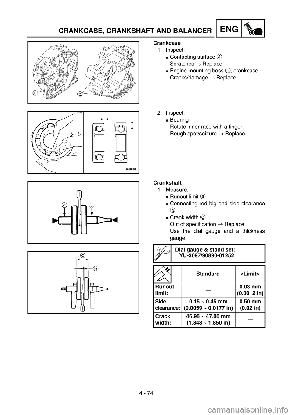
Crankcase
1. Inspect:
�Contacting surface a
Scratches → Replace.
�Engine mounting boss b, crankcase
Cracks/damage → Replace.
2. Inspect:
�Bearing
Rotate inner race with a finger.
Rough spot/seizure → Replace.
Crankshaft
1. Measure:
�Runout limit a
�Connecting rod big end side clearance
b
�Crank width c
Out of specification → Replace.
Use the dial gauge and a thickness
gauge.
Dial gauge & stand set:
YU-3097/90890-01252
Standard
Runout
limit:—0.03 mm
(0.0012 in)
Side
clearance:0.15 ~ 0.45 mm
(0.0059 ~ 0.0177 in)0.50 mm
(0.02 in)
Crack
width:46.95 ~ 47.00 mm
(1.848 ~ 1.850 in)—
Page 414 of 610
4 - 78
ENGTRANSMISSION, SHIFT CAM AND SHIFT FORK
TRANSMISSION, SHIFT CAM AND SHIFT FORK
Extent of removal:1 Shift cam and shift fork removal2 Main axle and drive axle removal
Extent of removal Order Part name Q’ty Remarks
TRANSMISSION, SHIFTCAM
AND SHIFT FORK REMOVAL
Preparation for removal Engine Refer to “ENGINE REMOVAL” section.
Separate the crankcase. Refer to “CRANKCASE, CRANKSHAFT
AND BALANCER” section.
1 Shift fork guide bar 1 (short) 1
2 Shift fork guide bar 2 (long) 1
3 Shift cam 1
4 Shift fork 2 (C) 1
5 Shift fork 3 (R) 1
6 Shift fork 1 (L) 1
7 Main axle 1
Refer to “REMOVAL POINTS”.
8 Drive axle 1
9 Push rod 2 1
10 Washer 1
1
2
Page 422 of 610
4 - 82
ENGTRANSMISSION, SHIFT CAM AND SHIFT FORK
3. Install:
�Plain washer 1
�Circlip 2
NOTE:
�Be sure the circlip sharp-edged corner a is
positioned opposite side to the plain washer
and gear b.
�Be sure the circlip end c is positioned at
axle spline groove d.
New
4. Install:
�Push rod 2
On main axle.
NOTE:
Apply the engine oil on the push rod 2.
5. Install:
�Washer 1
On drive axle.
6. Install:
�Main axle
�Drive axle
Install these in the left crankcase at the
same time.
NOTE:
�Apply the lithium soap base grease on the oil
seal lip.
�When installing the drive axle into the crank-
case, pay careful attention to the crankcase
oil seal lip.
Page 424 of 610
4 - 83
ENGTRANSMISSION, SHIFT CAM AND SHIFT FORK
Shift cam and shift fork
1. Install:
�Shift fork 1 (L) 1
�Shift fork 2 (C) 2
�Shift fork 3 (R) 3
NOTE:
�Mesh the shift fork #1 (L) with the 2nd wheel
gear and #3 (R) with the 4th wheel gear on
the drive axle.
�Mesh the shift fork #2 (C) with the 3rd pinion
gear on the main axle.
2. Install:
�Shift cam 1
NOTE:
Apply the engine oil on the shift cam.
3. Install:
�Shift fork guide bar 1 (short) 1
�Shift fork guide bar 2 (long) 2
NOTE:
�Apply the engine oil on the guide bars.
�Be sure the long bar is inserted into the shift
forks #1 and #3 and the short one into #2.
4. Check:
�Shifter operation
�Transmission operation
Unsmooth operation → Repair.
Page 426 of 610
5 - 1
CHASFRONT WHEEL AND FRONT BRAKE (TT-R125/TT-R125E)
EC500000
CHASSIS
FRONT WHEEL AND FRONT BRAKE (TT-R125/TT-R125E)
Extent of removal:1 Front wheel removal2 Wheel bearing removal
3 Brake shoe plate assembly removal and disassembly
Extent of removal Order Part name Q’ty Remarks
Preparation for removalFRONT WHEEL AND DRUM
BRAKE
Hold the machine by placing the
suitable stand under the engine.
WARNINGSupport the machine securely so there is no
danger of it falling over.
1 Brake cable holder 1
2 Brake cable 1 Disconnect at the lever side, first.
3 Axle nut 1
4 Wheel axle 1
5 Front wheel 1
6 Collar set 1
7 Brake shoe plate assembly 1
8 Oil seal 1
9 Wheel bearing 2 Refer to “REMOVAL POINTS”.
10Spacer
1
2
3
1


EC500000
CHASSIS
FRONT WHEEL AND FRONT BRAKE (TT-R125/TT-R125E)
Extent of removal:1 Front wheel removal2 Wheel bearing removal
3 Brake shoe pla")