PERIODIC MAINTENANCE AND MINOR REPAIR
6-33
6
EAU24360
Front wheel
EAU24470
To remove the front wheel
WARNING
EWA10820
�
It is advisable to have a Yamaha
dealer service the wheel.
�
Securely support the motor-
cycle so that there is no dangerof it falling over.
1. Place the motorcycle on the cen-
terstand.
2. Loosen the front wheel axle pinch
bolt, then the wheel axle and the
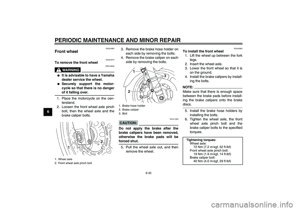
brake caliper bolts.3. Remove the brake hose holder on
each side by removing the bolts.
4. Remove the brake caliper on each
side by removing the bolts.
CAUTION:
ECA11050
Do not apply the brake after the
brake calipers have been removed,
otherwise the brake pads will beforced shut.
5. Pull the wheel axle out, and then
remove the wheel.
EAU24860
To install the front wheel
1. Lift the wheel up between the fork
legs.
2. Insert the wheel axle.
3. Lower the front wheel so that it is
on the ground.
4. Install the brake calipers by install-
ing the bolts.NOTE:Make sure that there is enough space
between the brake pads before install-
ing the brake calipers onto the brakediscs.
5. Install the brake hose holders by
installing the bolts.
6. Tighten the wheel axle, the front
wheel axle pinch bolt and the
brake caliper bolts to the specified
torques.
1. Wheel axle
2. Front wheel axle pinch bolt
1. Brake hose holder
2. Brake caliper
3. Bolt
Tightening torques:
Wheel axle:
72 Nm (7.2 m·kgf, 52 ft·lbf)
Front wheel axle pinch bolt:
19 Nm (1.9 m·kgf, 14 ft·lbf)
Brake caliper bolt:
40 Nm (4.0 m·kgf, 29 ft·lbf)
5VXE1.book Page 33 Monday, February 9, 2004 5:39 PM
PERIODIC MAINTENANCE AND MINOR REPAIR
6-35
6
NOTE:The drive chain does not need to be
disassembled in order to remove andinstall the rear wheel.
6. While supporting the brake caliper
and slightly lifting the wheel, pull
the wheel axle out.NOTE:A rubber mallet may be useful to tap thewheel axle out.
7. Remove the wheel.
CAUTION:
ECA11070
Do not apply the brake after the
wheel has been removed together
with the brake disc, otherwise thebrake pads will be forced shut.
EAU32940
To install the rear wheel
1. Install the wheel and the brake cal-
iper bracket by inserting the wheel
axle from the right-hand side.NOTE:�
Make sure that the retainer on the
swingarm is inserted into the slot in
the brake caliper bracket.
�
Make sure that there is enough
space between the brake pads be-fore installing the wheel.2. Install the drive chain onto the rear
sprocket, and then adjust the drive
chain slack. (See page 6-21.)
3. Install the axle nut, and then lower
the rear wheel so that it is on the
ground.
4. Tighten the axle nut to the speci-
fied torque.
1. Wheel axle
2. Drive chain slack adjusting nut
3. Locknut
4. Brake caliper bracket
5. Brake caliper
1. Retainer
2. SlotTightening torque:
Axle nut:
120 Nm (12.0 m·kgf, 87 ft·lbf)
5VXE1.book Page 35 Monday, February 9, 2004 5:39 PM