Page 65 of 90

PERIODIC MAINTENANCE AND MINOR REPAIR
6-26
6
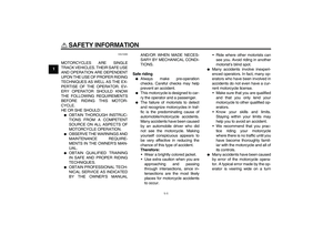
WARNING
EWA10760
�
Electrolyte is poisonous and
dangerous since it contains sul-
furic acid, which causes severe
burns. Avoid any contact with
skin, eyes or clothing and al-
ways shield your eyes when
working near batteries. In case
of contact, administer the fol-
lowing FIRST AID.
EXTERNAL: Flush with plenty
of water.
INTERNAL: Drink large quan-
tities of water or milk and im-
mediately call a physician.
EYES: Flush with water for 15
minutes and seek prompt
medical attention.
�
Batteries produce explosive hy-
drogen gas. Therefore, keep
sparks, flames, cigarettes, etc.,
away from the battery and pro-
vide sufficient ventilation when
charging it in an enclosed
space.
�
KEEP THIS AND ALL BATTER-
IES OUT OF THE REACH OFCHILDREN.
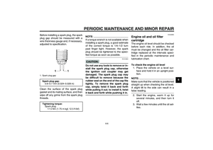
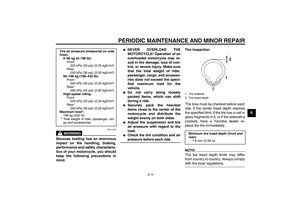
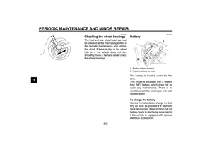
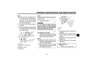
To store the battery
1. If the vehicle will not be used for
more than one month, remove the
battery, fully charge it, and then
place it in a cool, dry place.
2. If the battery will be stored for more
than two months, check it at least
once a month and fully charge it if
necessary.
3. Fully charge the battery before in-
stallation.
4. After installation, make sure that
the battery leads are properly con-
nected to the battery terminals.
CAUTION:
ECA10630
�
Always keep the battery
charged. Storing a discharged
battery can cause permanent
battery damage.
�
To charge a sealed-type (MF)
battery, a special (constant-volt-
age) battery charger is required.
Using a conventional batterycharger will damage the battery.
If you do not have access to a
sealed-type (MF) battery charg-
er, have a Yamaha dealer
charge your battery.
U1B3E0E0.book Page 26 Monday, February 9, 2004 2:27 PM
Page 66 of 90

If a fuse is blown,")
PERIODIC MAINTENANCE AND MINOR REPAIR
6-27
6
EAU32841
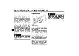
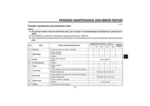
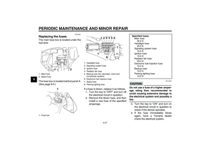
Replacing the fuses The main fuse box is located under the
fuel tank.
The fuse box is located behind panel A.
(See page 6-5.)
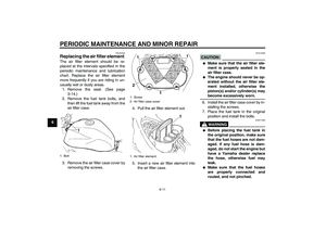
If a fuse is blown, replace it as follows.
1. Turn the key to “OFF” and turn off
the electrical circuit in question.
2. Remove the blown fuse, and then
install a new fuse of the specified
amperage.
CAUTION:
ECA10640
Do not use a fuse of a higher amper-
age rating than recommended to
avoid causing extensive damage to
the electrical system and possibly afire.
3. Turn the key to “ON” and turn on
the electrical circuit in question to
check if the device operates.
4. If the fuse immediately blows
again, have a Yamaha dealer
check the electrical system.
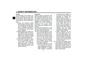
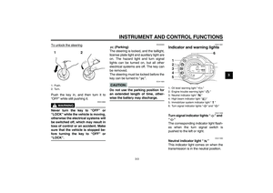
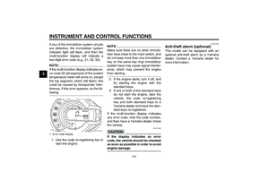
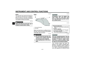
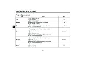
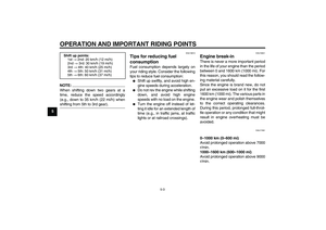
1. Main fuse
2. Spare fuse
1. Fuse box
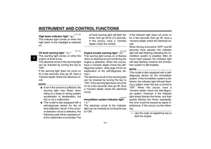
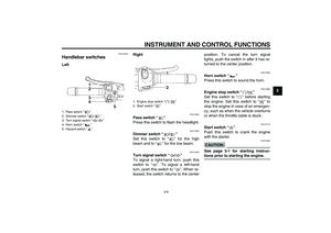
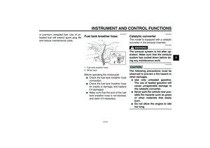
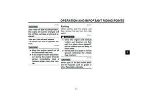
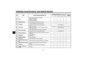
1. Headlight fuse
2. Signaling system fuse
3. Ignition fuse
4. Radiator fan fuse
5. Backup fuse (for odometer, clock and
immobilizer system)
6. Electronic fuel injection fuse
7. Spare fuse
8. Parking lighting fuse
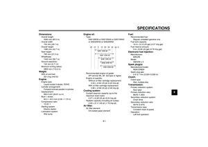
Specified fuses:
Main fuse:
30.0 A
Headlight fuse:
20.0 A
Signaling system fuse:
10.0 A
Ignition fuse:
10.0 A
Radiator fan fuse:
20.0 A
Electronic fuel injection fuse:
10.0 A
Backup fuse:
10.0 A
Parking lighting fuse:
10.0 A
U1B3E0E0.book Page 27 Monday, February 9, 2004 2:27 PM
Page 67 of 90

PERIODIC MAINTENANCE AND MINOR REPAIR
6-28
6
EAU34380
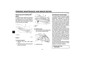
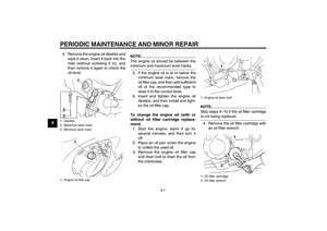
Replacing the headlight bulb This model is equipped with a quartz
bulb headlight. If the headlight bulb
burns out, replace it as follows.
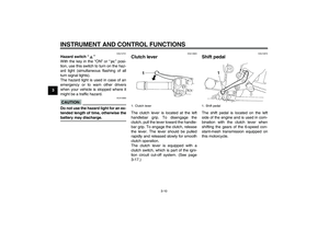
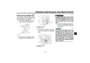
1. Remove the headlight unit by re-
moving the bolts on each side.
2. Disconnect the headlight coupler,
and then remove the bulb cover.3. Unhook the headlight bulb holder,
and then remove the defective
bulb.
WARNING
EWA10790
Headlight bulbs get very hot. There-
fore, keep flammable products away
from a lit headlight bulb, and do not
touch the bulb until it has cooleddown.
4. Place a new headlight bulb into po-
sition, and then secure it with the
bulb holder.CAUTION:
ECA10660
Do not touch the glass part of the
headlight bulb to keep it free from
oil, otherwise the transparency of
the glass, the luminosity of the bulb,
and the bulb life will be adversely af-
fected. Thoroughly clean off any dirt
and fingerprints on the headlight
bulb using a cloth moistened with al-cohol or thinner.
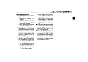
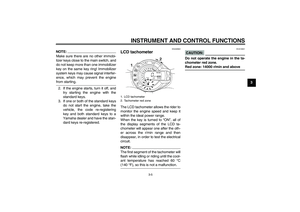
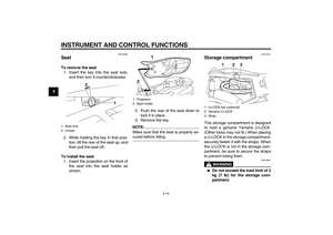
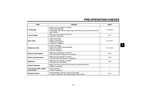
1. Bolt
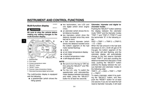
1. Headlight bulb cover
2. Headlight coupler
1. Headlight bulb holder
2. Headlight bulb
U1B3E0E0.book Page 28 Monday, February 9, 2004 2:27 PM
Page 68 of 90
PERIODIC MAINTENANCE AND MINOR REPAIR
6-29
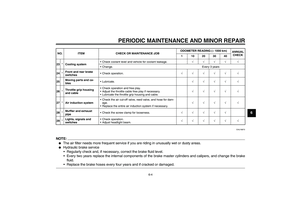
65. Install the headlight bulb cover,
and then connect the coupler.
6. Install the headlight unit by install-
ing the bolts.
7. Have a Yamaha dealer adjust the
headlight beam if necessary.
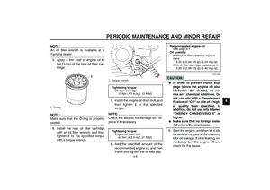
EAU32821
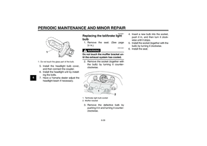
Replacing the tail/brake light
bulb 1. Remove the seat. (See page
3-14.)
WARNING
EWA12301
Do not touch the muffler bracket un-til the exhaust system has cooled.
2. Remove the socket (together with
the bulb) by turning it counter-
clockwise.
3. Remove the defective bulb by
pushing it in and turning it counter-
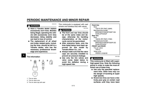
clockwise.4. Insert a new bulb into the socket,
push it in, and then turn it clock-
wise until it stops.
5. Install the socket (together with the
bulb) by turning it clockwise.
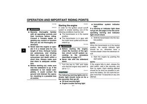
6. Install the seat.
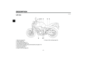
1. Do not touch the glass part of the bulb.
1. Tail/brake light bulb socket
2. Muffler bracket
U1B3E0E0.book Page 29 Monday, February 9, 2004 2:27 PM
Page 69 of 90
PERIODIC MAINTENANCE AND MINOR REPAIR
6-30
6
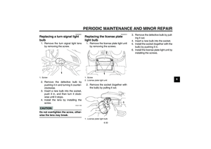
EAU24201
Replacing a turn signal light
bulb 1. Remove the turn signal light lens
by removing the screw.
2. Remove the defective bulb by
pushing it in and turning it counter-
clockwise.
3. Insert a new bulb into the socket,
push it in, and then turn it clock-
wise until it stops.
4. Install the lens by installing the
screw.CAUTION:
ECA11190
Do not overtighten the screw, other-wise the lens may break.
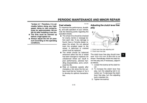
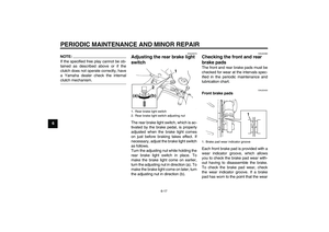
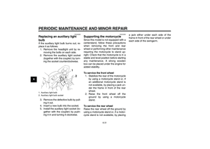
EAU24310
Replacing the license plate
light bulb 1. Remove the license plate light unit
by removing the screws.
2. Remove the socket (together with
the bulb) by pulling it out.3. Remove the defective bulb by pull-
ing it out.
4. Insert a new bulb into the socket.
5. Install the socket (together with the
bulb) by pushing it in.
6. Install the license plate light unit by
installing the screws.
1. Screw
1. Screw
2. License plate light unit
1. License plate light bulb
U1B3E0E0.book Page 30 Monday, February 9, 2004 2:27 PM
Page 70 of 90

PERIODIC MAINTENANCE AND MINOR REPAIR
6-31
6
EAU34400
Replacing an auxiliary light
bulb If the auxiliary light bulb burns out, re-
place it as follows.
1. Remove the headlight unit by re-
moving the bolts on each side.
2. Remove the auxiliary light socket
(together with the coupler) by turn-
ing the socket counterclockwise.
3. Remove the defective bulb by pull-
ing it out.
4. Insert a new bulb into the socket.
5. Install the auxiliary light socket (to-
gether with the coupler) by push-
ing it in and turning it clockwise.
EAU24350
Supporting the motorcycle Since this model is not equipped with a
centerstand, follow these precautions
when removing the front and rear
wheel or performing other maintenance
requiring the motorcycle to stand up-
right. Check that the motorcycle is in a
stable and level position before starting
any maintenance. A strong wooden
box can be placed under the engine for
added stability.
To service the front wheel
1. Stabilize the rear of the motorcycle
by using a motorcycle stand or, if
an additional motorcycle stand is
not available, by placing a jack un-
der the frame in front of the rear
wheel.
2. Raise the front wheel off the
ground by using a motorcycle
stand.
To service the rear wheel
Raise the rear wheel off the ground by
using a motorcycle stand or, if a motor-
cycle stand is not available, by placinga jack either under each side of the
frame in front of the rear wheel or under
each side of the swingarm.
1. Auxiliary light bulb
2. Auxiliary light bulb socketU1B3E0E0.book Page 31 Monday, February 9, 2004 2:27 PM
Page 71 of 90

PERIODIC MAINTENANCE AND MINOR REPAIR
6-32
6
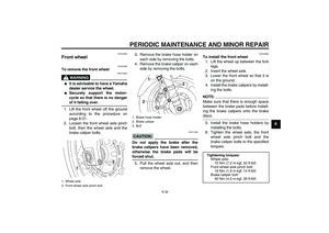
EAU24360
Front wheel
EAU34390
To remove the front wheel
WARNING
EWA10820
�
It is advisable to have a Yamaha
dealer service the wheel.
�
Securely support the motor-
cycle so that there is no dangerof it falling over.
1. Lift the front wheel off the ground
according to the procedure on
page 6-31.
2. Loosen the front wheel axle pinch
bolt, then the wheel axle and the
brake caliper bolts.3. Remove the brake hose holder on
each side by removing the bolts.
4. Remove the brake caliper on each
side by removing the bolts.
CAUTION:
ECA11050
Do not apply the brake after the
brake calipers have been removed,
otherwise the brake pads will beforced shut.
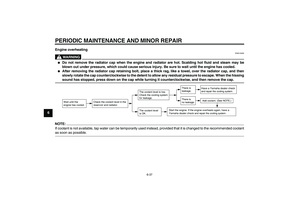
5. Pull the wheel axle out, and then
remove the wheel.
EAU24860
To install the front wheel
1. Lift the wheel up between the fork
legs.
2. Insert the wheel axle.
3. Lower the front wheel so that it is
on the ground.
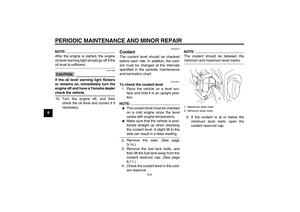
4. Install the brake calipers by install-
ing the bolts.NOTE:Make sure that there is enough space
between the brake pads before install-
ing the brake calipers onto the brakediscs.
5. Install the brake hose holders by
installing the bolts.
6. Tighten the wheel axle, the front
wheel axle pinch bolt and the
brake caliper bolts to the specified
torques.
1. Wheel axle
2. Front wheel axle pinch bolt
1. Brake hose holder
2. Brake caliper
3. Bolt
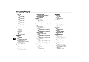
Tightening torques:
Wheel axle:
72 Nm (7.2 m·kgf, 52 ft·lbf)
Front wheel axle pinch bolt:
19 Nm (1.9 m·kgf, 14 ft·lbf)
Brake caliper bolt:
40 Nm (4.0 m·kgf, 29 ft·lbf)
U1B3E0E0.book Page 32 Monday, February 9, 2004 2:27 PM
Page 72 of 90
PERIODIC MAINTENANCE AND MINOR REPAIR
6-33
67. Push down hard on the handlebar
several times to check for proper
fork operation.
EAU25080
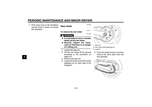
Rear wheel
EAU34411
To remove the rear wheel
WARNING
EWA10820
�
It is advisable to have a Yamaha
dealer service the wheel.
�
Securely support the motor-
cycle so that there is no dangerof it falling over.
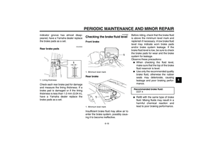
1. Loosen the axle nut.
2. Lift the rear wheel off the ground
according to the procedure on
page 6-31.
3. Remove the axle nut.
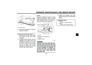
4. Loosen the locknut and drive chain
adjusting nut on each side of the
swingarm.5. Push the wheel forward, and then
remove the drive chain from the
rear sprocket.
1. Axle nut
2. Drive chain slack adjusting nut
3. Locknut
U1B3E0E0.book Page 33 Monday, February 9, 2004 2:27 PM