2004 VOLKSWAGEN GOLF PLUS Ecu
[x] Cancel search: EcuPage 323 of 541
Introduction
In thi s section yo u'll find inform ation on th e fo l
l ow ing:
Storage . . . . . . . . . . . . . . . . . . . . . . . . . . . . . . . .
Pr epara tio ns fo r workin g in the eng ine co m
In an p age
a w hee l page
Tire mobili ty page 336
Storage
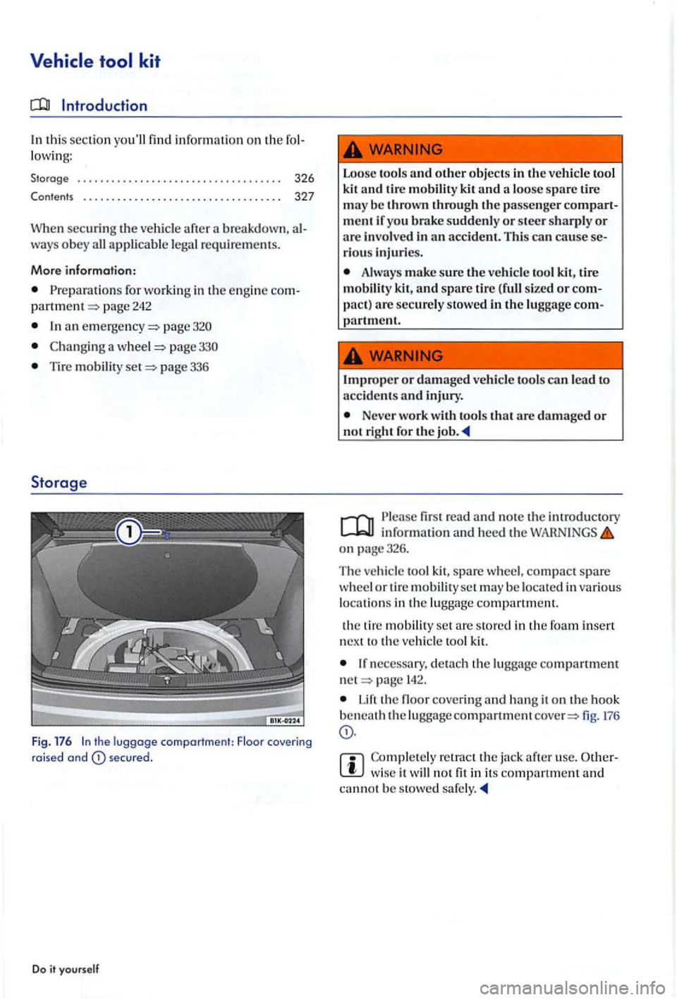
Fig. 176 In the luggage compartment: Floor covering raised and secu red.
Do it yourse lf
Loose tools and other objects kit and a lo o se spare tire may be thrown through the passenger compart
m ent if yo u brake suddenly or stee r sharply or are involv ed in an accident. This can cause se
r io u s injuri es.
Alw ays make sure the ve hicl e to ol kit , tire
mobili ty kit, and spare tire sized or com
pact ) are securel y stow ed in th e luggage com-ment.
I
mprope r or damaged vehicl e tools can lead to
a ccid ent s and injury .
Neve r work with tools that are damage d or not right for the job .
firs t read and note th e int rod uc tory inform ation an d heed th e o n page326.
T he ve hicle t
ool kit, spare wheel, compact spare w hee l or tir e mobilit y set may be locate d in various
l oca tions in the lu ggage compart men t.
th e tir e m obilit y
set are stored in the foam insert
n ex t to t he ve hicl e too l kit.
If necessary, de ta ch the luggage compartment net page
Lift th e floo r cover ing and ha ng it on th e hook beneath the luggageco mpart mem fig. 176
w ise it not fit in its co mpart ment and ca nnot be stowe d sa fe ly.
Page 331 of 541
Checklis t (continued)
7. th e jack so that its ba se is directly underneath th e lift page 333, fig. 185, making
sure th at the e ntire base of the jack rests securely on th e gro und.
B. Align the ja ck and w ind up th e jack claw at th e sa me time, pa ge 333, fig. 185 (ar row).
9. c ra nking up the jack until th e whee l is ju st a littl e
Usc only jacks approve d by Volk swage n fo r the ve hicle. Other jacks might slip , eve n those
ap pro ved for oth er Volkswagen models, but not
for your ve hicl e.
Always set up t h e jack on firm and leve l
ground. The vehicle may slip off the jack if the jack is resting on soft or slop ing ground. If n eces
sary place a sturdy board under the jack.
a hard, slip pery surfa ce (such
to prevent the jack from slipping.
Posit io n the jack only at the describ ed hide lift points. Befor e yo u rai se your vehicl e, almake sure the jack claw properly grip s th e
ve rtical rib under t11e sill so that th e ja ck d oes
n ot slip off when yo u are raisi ng the ve hicle page 333, fig. 185.
Do it yourself
Neve r have an y part of your body (such as your arm or leg) under the v ehicl e when it is
su pported by the ja ck. Never le t o ther pe rso ns have any part of their body under th e ve hicle, ther!
floor jack, a lways make sure th at t11e ve hicl e is
sa fe ly supported on safety stand s intended for that purpose that are strong e nough to support the weight of th e vehi cle.
Neve r lift t11e ve hicle when it is to one side or the e ngine is running.
Do not s tart th e eng in e while th e ve hicle is
support e d b y jack. Engine vib ratio ns ca use the vehi cle to slip off the jack.
Disr egarding
the safety- rela te d ch eckl is t may
l ea d to acc idents and serio us injuri es.
Alway s rev ie w and follow the ch ec kli st. Follow accep te d sa fety pract ices and use
common se nse.
Page 332 of 541
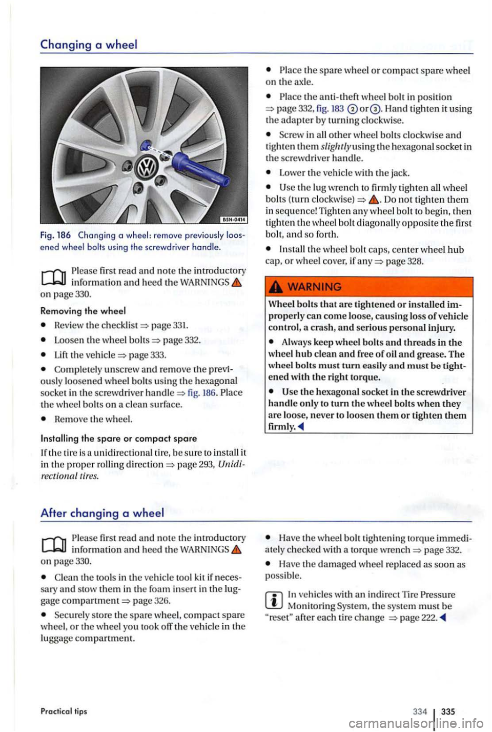
Fig. 186 Chang ing a wheel: remove previo usly ened wheel bolts using the screwdr iver handle .
first read and no te th e introduct ory inform ation and hee d the on page330.
R emov
ing the wheel
Revie w the pag e 331.
Loosen th e w heel page 332.
the page 333.
Complete ly unscrew and rem ove the ously loosened whee l bolt s using the hexago nal
soc ke t in the sc rew dri ver h andl e fig. 186. th e wheel bolts on a clea n surf ace .
Re m ove the w heel.
Installing the spare or compact spare
unidirectiona l tir e, b e sure to install it in the proper ro llin g pag e 293, tires.
After changing a
fir st read and note th e introductory info rm ation and hee d th e on page330.
Clea n th e tools in the vehicl e too l kit if sary and stow th em in th e foa m gage pag e 326.
Securely sto re th e spare whee l, compact spare
w heel, o r th e whee l yo u took off the vehicle in th e
lugga ge compartment.
Practical tips
the spare whee l o r compac t spare wheel on th e ax le.
th e a nti-th eft wheel bolt in position 332, fig. 183 Han d tigh ten it using the adapter b y turnin g clockw ise.
i n all other w hee l b olts clockw ise and tig ht en them slig/ u/yusin g th e hexago nal socket in
the screwdrive r handle.
Lower the ve hicl e with the jack .
the lug wre n ch to firml y tighten all wheel
bolt s (turn Do not tighten them in sequ en ce ! Tight en any wheel bolt to beg in, th en tighten th e wheel bo lt dia gonally opposite the first
b o lt, and so for th.
page 328.
Wh
eel bolts that a re tighte ned or installed p rope rly can come loo se, causing loss of vehicle
contro l,
Always keep whee l bolt s and threads in the
w hee l hub clean and free of oil and grease . The
wheel bolts mus t turn easil y and must be
the hexagona l socket in th e sc rewdriver
handl e o nly to turn th e w hee l bolt s when they are loo se, never to loosen th em or
Have th e w heel b o lt tightening to rqu e ately c hec ke d with a to rqu e wre nch page 332.
Have the dam aged whee l re p laced as soo n as
poss ible.
In ve hicles with indir ect T ir e Monitoring th e sys te m mu st b e after each tir e ch a nge
334 335
Page 342 of 541
Note
After replacing a headlight bulb or other light bulb, always make sure that the rubber covers or plastic ca ps have been properly and securely rein
s talled to help prevent water from gettin g into the
e lec trica l connection s and headlight hou sin g and damaging th e e lectrical system_
Please first read and note the introductory information and heed the o n page 344.
Lights up Possible cau se
Light bulb of th e exterio r ve hicle lighting . not working .
W
hen the ignit ion is swi tc h ed on, severa l wa rnin g
and indi cator lights come on briefl y for a fun ction
check. They go out after a few seconds.
Failure to heed warning lights and instrument cluste r text messages can cause the ve hicle to break down in traffic and result in a co llision and serious personal injury.
Never ignore warning lights or tex t WARNINGS.
tips
Proper response
R
epl ace the ligh t bu lb.
WARNING
A lways sto p th e ve hicl e as soon as it is safe to
do so .
Note
Failure to heed warning lights or tex t WARNINGS can result in vehicl e damage.
344 345
Page 344 of 541
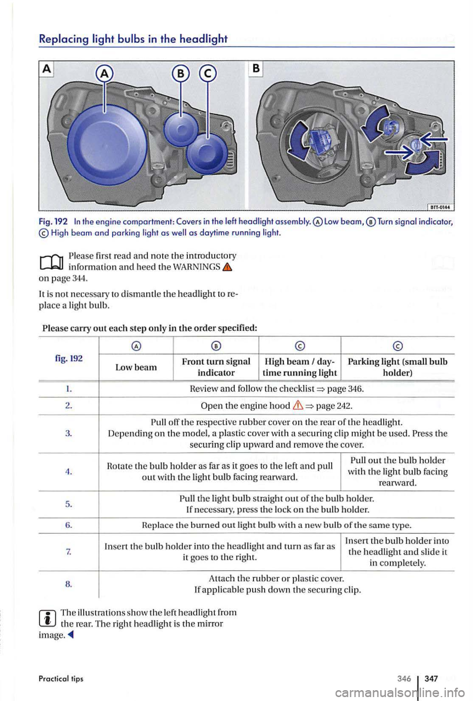
in the
Tu rn signal indicator, High beam and parki ng light as as daytime r u n ni ng lig ht.
fir st read and no te the introductory inform ation and heed the o n page344.
is no t necessary to dismantle th e headlight
pl ace a light bulb.
carry out each step only in the order specified:
fig. !92
Front turn sig n al
Low beam indicator H ig h beam day-Parking light (small bulb time running light h older)
Hev ie w and follow th e page 3 46.
2.
t h e engine page 2 42.
off the respective rubber co ve r on th e re a r o f th e 3. Dep endi ng on the model, a plas tic cove r w ith a securing cl ip mig h t be used. th e secu ring cl ip upward and r emove the c o ve r.
Rotate th e bulb h older as far as it goes to the left and pull out the bul b h old e r 4. with the light bulb Faci ng
out with t h e ligh t bulb facing rearw ard. rearward.
5 .
the light bulb straight out o f th e bulb ho ld er.
I f necessary, press the lo ck on th e bulb holder.
6. the burned out light bulb with bulb of th e ty pe.
I n
sert the bulb holder into the headlight and turn far as Insert th e bulb holder into 7. th e headligh t and sli d e it
it goes to the right.
in complete ly .
8 . Attac
h
the rubber or pla sti c c over. If applicable push down the securing cl ip.
The illu stra ti ons s how the le ft headlight fro m the re ar. The right h eadlight is the mirror ima ge.
Practical lips 346 347
Page 347 of 541
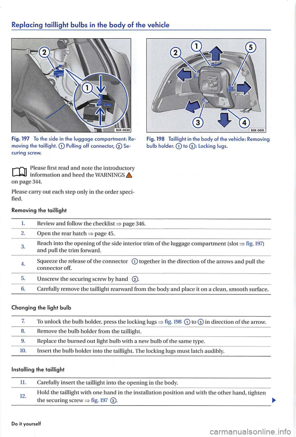
Replacing tailligh t bulbs in the body of the vehicle
fig. 197 To th e s id e in th e luggage comportment: Remov ing th e cur in g screw.
Please fir st read
o n page 344 .
P l
ease carry out each ste p onl y in the order speci
fied.
Removing the
I. Review and the page 346.
2 . the rear page 45.
Fig. 198 to L oc king lugs .
3. 197) and pull the trim forwa rd .
4.
5.
6.
the re lease of th e connector together in th e direction of the arrows and th e connector otT.
th e securing screw by hand
Care full y re move th e taillig ht reanvard from th e body and place it on a clea n , s mooth surface.
Changing the light bulb
7. To unlock the bulb hold er, press th e locking fig. 198 to in direction th e arrow.
8 . Hem
ove th e bulb ho lder th e ta illi ght.
9 . Re
place the burned out light bulb w ith a n ew bulb or the same t ype.
Insert the bulb holde r into the tailli gh t. The lockin g lugs must latch a udibly.
II. Carefull y insert th e ta illight into the op en in g in the body.
12 . Hold the ta illight w ith o ne hand in th e in stallatio n position and wi th the othe r hand, tighte n
t h e
securing 197
Do it yo urself
Page 348 of 541
Check for prop er in stallatio n and secure fit of
Attac h t he page fig. to the bul b ho ld er.
H eplace the s id e inte rio r tr im of the lu gg age co mpartm ent.
C lose t h e re ar hatch page 45 .
D ue to diff ere n t v ers io ns of t he th e
re p resentati on in the illustratio ns.
Taill ights w ith h av e a bulb fo r the turn signal. This bul b ca n b e
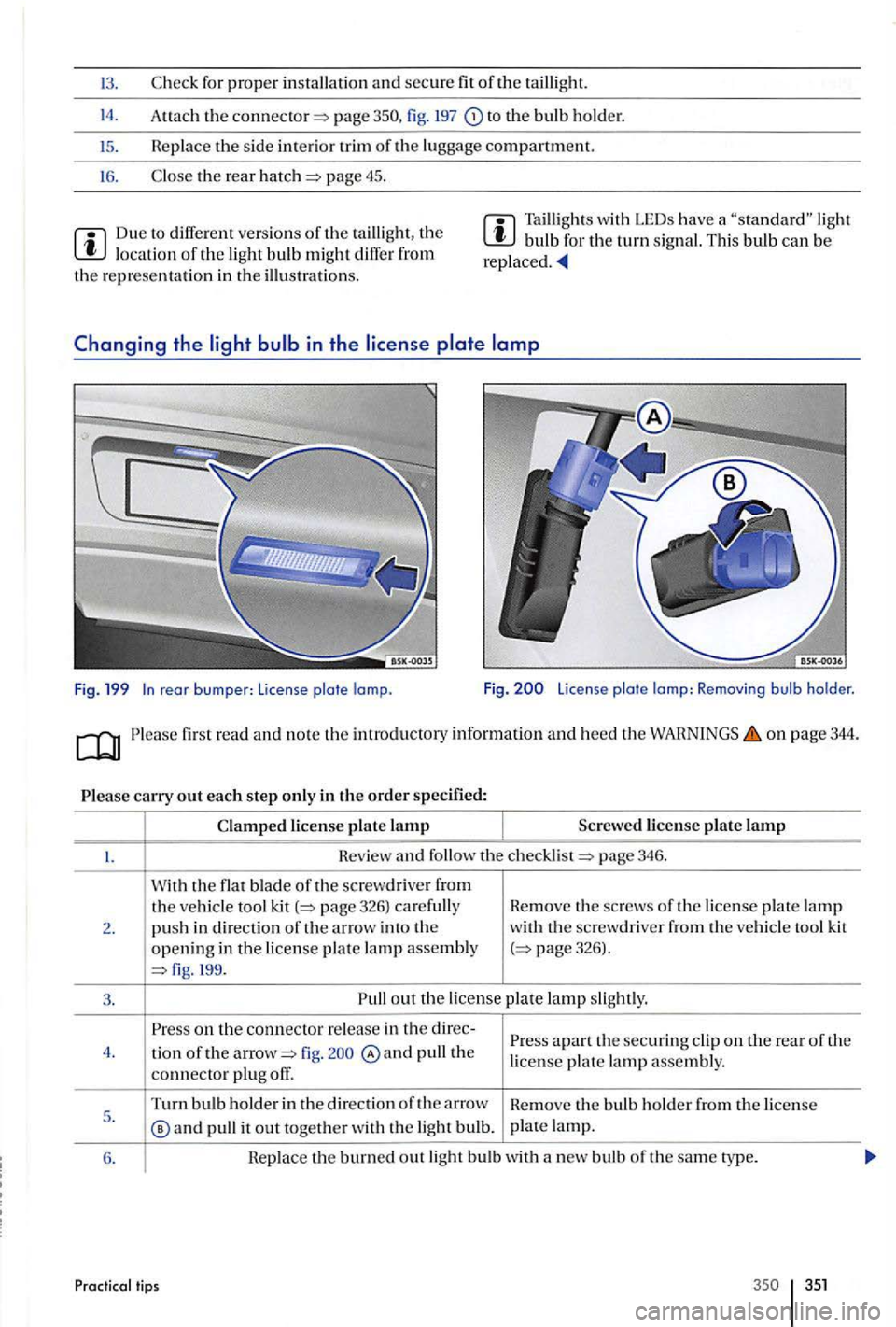
rear bumper: License plate lamp. Fig. License plate lamp: Removing bulb holder.
on page 344.
page 346 .
W ith
the flat bla de o f the screwdriver fr om the ve hicl e tool kit
3 . out th e license la m p sligh tly.
o n the connecto r re le ase in th e apa rt th e sec urin g cl ip on the rear of t he
4 .
lio n of the fig . pull the license plat e lam p assembly .
connect o r plu g off.
Turn bulb ho ld er in the direc tio n of the arro w
He move th e bul b ho ld er fr om the license 5 .
®an d p ull it out togethe r w ith th e light bulb. p
la te lamp.
6.
Hepl ace the burned out light b ulb w ith a new bulb of the sam e typ e.
Practical tips 35 1
Page 349 of 541
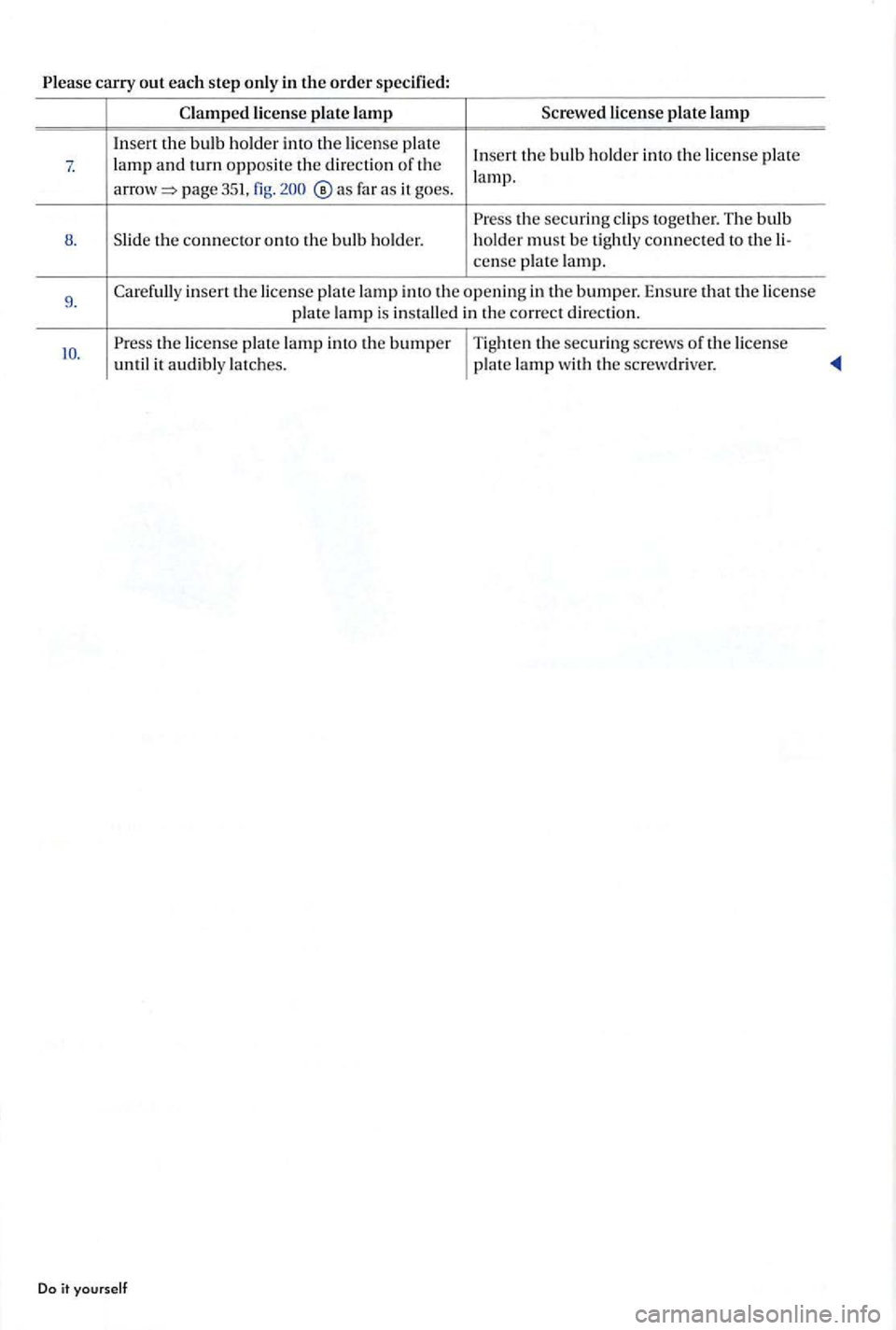
Please carry out each ste p only in the order sp ec ified:
Clampe d lic en se pla te lamp licen se plate lamp
I n se rt th e bu lb h old e r in to th e lice nse pla te Inse rt the bulb h older int o th e lice nse pla te 7 . lamp a nd turn op po site the direction of t h e
page 351, fig. far a s it go es. l
a m p.
Press the securin g cl ip s togeth er. The bulb 8 . th e connec to r onto th e bu lb ho ld e r. holder m
ust b e tightly conn ec te d t o th e li-
c e nse p late la m p.
9. inse rt th e lice nse pla te lamp into th e o penin g in the bumper. E n su re th at th e lice nse p late lamp is ins talle d in the co rrect dir ectio n.
Pre ss the lice nse p lat e lamp in to th e bumper T ig h te n th e sec urin g scre ws of th e lice nse
u nt il it a udibl y latc hes . pla te lamp w it h th e screw driver.
Do i t yourself