Page 426 of 491
11 -4 1
Maintenance and service
– CONTINUED –
tact your SUBARU dealer. !Checking the brake pedal reserve dis- tance
1) More than 2.56 in (65 mm)
Depress the pedal with a force of approximately 66 lb
(294 N, 30 kg) and measure the distance between the
upper surface of the pedal pad and the floor.
When the measurement is smaller than the specifica-
tion, or when the pedal does not operate smoothly,
contact with your SUBARU dealer.Clutch pedal (MT vehicles)
Check the clutch pedal free play and reserve distance
according to the maintenance schedule in the “War-
ranty and Maintenance Booklet”. ! Checking the clutch function
Check the clutch engagement and disengagement.
1. With the engine idling, check that there are no ab-
normal noises when the clutch pedal is depressed,
and that shifting into 1st or reverse feels smooth.
2. Start the vehicle by releasing the pedal slowly to
check that the engine and transmission smoothly cou-
ple without any sign of slippage.
1
HSB050BB
Page 427 of 491
11 - 4 2
Maintenance and service
!
Checking the clutch pedal free play
1) 0.16 – 0.51 in (4.0 –13.0 mm)
Lightly press the clutch pedal down with your finger
until you feel resistance, and check the free play.
If the free play is not within proper specification, con-
tact your SUBARU dealer.Replacement of brake pad and lining
The front disc brakes and the right rear disc brake
have an audible wear indicators on the brake pads. If
the brake pads wear close to their service limit, the
wear indicator makes a very audible scraping noise
when the brake pedal is applied.
If you hear this scraping noise each time you apply the
brake pedal, have the brake pads serviced by your
SUBARU dealer as soon as possible.
1
HSB049BBHS7012BA
Page 428 of 491

11 -4 3
Maintenance and service
– CONTINUED –
If you continue to drive despite the scraping
noise from the audible brake pad wear indica-
tor, it will result in the need for costly brake ro-
tor repair or replacement.
! Breaking-in of new brake pads and lin- ings
When replacing the brake pad or lining, use only gen-
uine SUBARU parts. After replacement, the new parts
must be broken in as follows: ! Brake pad and lining
While maintaining a speed of 30 to 40 mph (50 to 65
km/h), step on the brake pedal lightly. Repeat this five
or more times. ! Parking brake lining
1. Drive the vehicle at a speed of about 22 mph (35 km/h).
2. With the parking brake release button pushed in,
pull the parking brake lever SLOWLY and GENTLY.
(Pulling with a force of approximately 33 lb [147 N, 15 kg].)
3. Drive the vehicle for about 220 yards (200 meters) in this condition.
4. Wait 5 to 10 minutes for the parking brake to cool
down. Repeat this procedure.
5. Check the parking brake stroke. If the parking
brake stroke is out of the specified range, adjust it by
turning the adjusting nut located on the parking brake
lever.
Parking brake stroke:
7 – 8 notches / 44 lb (196 N, 20 kg)
A safe location and situation should be select-ed for break-in driving.
Pulling the parking brake lever too forcefully
may cause the rear wheels to lock. To avoid
this, be certain to pull the lever up slowly and
gently.
Page 429 of 491

11 - 4 4
Maintenance and service
Parking brake stroke
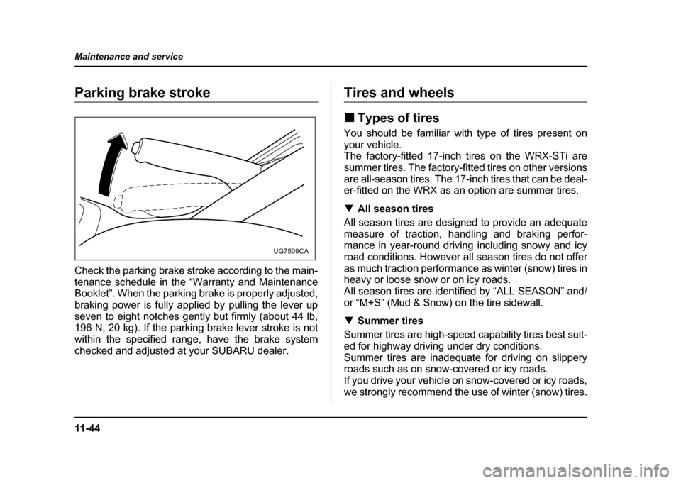
Check the parking brake stroke according to the main-
tenance schedule in the “Warranty and Maintenance
Booklet”. When the parking brake is properly adjusted,
braking power is fully applied by pulling the lever up
seven to eight notches gently but firmly (about 44 lb,
196 N, 20 kg). If the parking brake lever stroke is not
within the specified range, have the brake system
checked and adjusted at your SUBARU dealer.Tires and wheels !
Types of tires
You should be familiar with type of tires present on your vehicle.
The factory-fitted 17-inch tires on the WRX-STi are
summer tires. The factory-fitted tires on other versions
are all-season tires. The 17-inch tires that can be deal-
er-fitted on the WRX as an option are summer tires. ! All season tires
All season tires are designed to provide an adequate
measure of traction, handling and braking perfor-
mance in year-round driving including snowy and icy
road conditions. However all season tires do not offer
as much traction performance as winter (snow) tires in
heavy or loose snow or on icy roads.
All season tires are identified by “ALL SEASON” and/
or “M+S” (Mud & Snow) on the tire sidewall. ! Summer tires
Summer tires are high-speed capability tires best suit-
ed for highway driving under dry conditions.
Summer tires are inadequate for driving on slippery
roads such as on snow-covered or icy roads.
If you drive your vehicle on snow-covered or icy roads,
we strongly recommend the use of winter (snow) tires.
UG7509CA
Page 436 of 491

11 -5 1
Maintenance and service
– CONTINUED –
placing all four tires at the same time.
NOTE
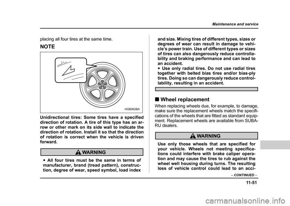
Unidirectional tires: Some tires have a specified
direction of rotation. A tire of this type has an ar-
row or other mark on its side wall to indicate the
direction of rotation. Install it so that the direction
of rotation is correct when the vehicle is drivenforward.
"All four tires must be the same in terms of
manufacturer, brand (tread pattern), construc-
tion, degree of wear, speed symbol, load index and size. Mixing tires of different types, sizes or
degrees of wear can result in damage to vehi-
cle’s power train. Use of different types or sizes
of tires can also dangerously reduce controlla-
bility and braking performance and can lead to
an accident."
Use only radial tires. Do not use radial tires
together with belted bias tires and/or bias-ply
tires. Doing so can dangerously reduce control-
lability, resulting in an accident.
! Wheel replacement
When replacing wheels due, for example, to damage,
make sure the replacement wheels match the specifi-
cations of the wheels that are fitted as standard equip-
ment. Replacement wheels are available from SUBA-
RU dealers.
Use only those wheels that are specified for
your vehicle. Wheels not meeting specifica-
tions could interfere with brake caliper opera-
tion and may cause the tires to rub against the
wheel well housing during turns. The resulting
loss of vehicle control could lead to an acci-
HGB062BA
Page 450 of 491
11 -6 5
Maintenance and service
– CONTINUED –
Wattage Bulb No.
1) Front turn signal 12V–21W —
2) Spot light 12V–8W —
3) Room light 12V–8W —
4) Parking light 12V–5W 168
5) Low beam head light U.S. spec. WRX-STi 12V-35W D2R Except U.S. spec. WRX-STi 12V-55W H1
6) Front fog light 12V–55W H3
7) High beam head light 12V–60W 9005 (HB3)
8) Trunk room light 12V–16W W16W
9) High mount stop light Sedan
(in compartment) 12V–18W 921
(in rear spoiler) 12V–1.2W —
Wagon 12V–13W 912
10) Backup light 12V–21W 7440
11) Rear turn signal 12V–21W (Amber)—
12) Brake light 12V–21W 7440
13) Tail light 12V–21/5W 7443
14) Brake/tail light 12V–21/5W 7443
15) License plate light 12V–5W 168 16) Cargo area light 12V–13W —
Wattage Bulb No.
Page 459 of 491
11 - 7 4
Maintenance and service
!
Rear combination lights
! Sedan
1. Remove the clip from the rear trunk trim with a reg-
ular screwdriver. 1) Backup light
2) Rear turn signal light
3) Brake light
4) Tail light
5) Brake/tail light
2. Open the rear portion of the side trunk trim panel.
3. Remove the bulb holder from the rear combination
light assembly by turning it counterclockwise.
4. Remove the bulb from the socket by pushing it and
turning counterclockwise. Install a new bulb.
5. Set the bulb holder into the rear combination light
assembly and turn it clockwise until it locks.
6. Secure the rear trunk trim panel with the clips.
UGB538BA
554
2
3
1
UGB539BB
Page 461 of 491
11 - 7 6
Maintenance and service
1) Tail/brake light
2) Rear turn signal light
3) Backup light
3. Remove the bulb holder from the rear combination
light assembly by turning it counterclockwise.
4. Remove the bulb from the socket by pushing it and
turning counterclockwise. Install a new bulb.
5. Set the bulb holder into the rear combination light
assembly and turn it clockwise until it locks.
6. Close the cover and latch the lock.
7. Reinstall the rear combination light assembly and
its side cover. !
License plate light
1. Remove the mounting screws using a phillips
screwdriver.
2. Remove the cover and lens.
3. Pull the bulb out of the socket. Install a new bulb.
4. Reinstall the lens and cover.
5. Tighten the mounting screws.
2
1
3
UGB542BB
UGB543BA