Page 21 of 491
18
!
Instrument panel
12345 6
7
8
9
11
12
13
14
15
16 10
UGF056BB
1) Door locks (page 2-3)
2) Light control lever (page 3-29)
3) Combination meter (page 3-15)
4) Wiper control lever (page 3-35)
5) Hazard warning flasher switch
(page 3-6)
6) Audio (page 5-1)
7) Gear shift lever (MT) (page 7- 15)/Selector lever (AT) (page 7-
21)
8) Outside mirror switch (page 3-
48)
9) Climate control (page 4-1)
10) Cruise control (page 7-37)
11) Horn (page 3-50)
12) SRS airbag (page 1-52)
13) Tilt steering (page 3-49)
14) Fuse box (page 11-60)
15) Hood lock release (page 11-5)
16) Power window (page 2-22)
Page 355 of 491

9-4
In case of emergency
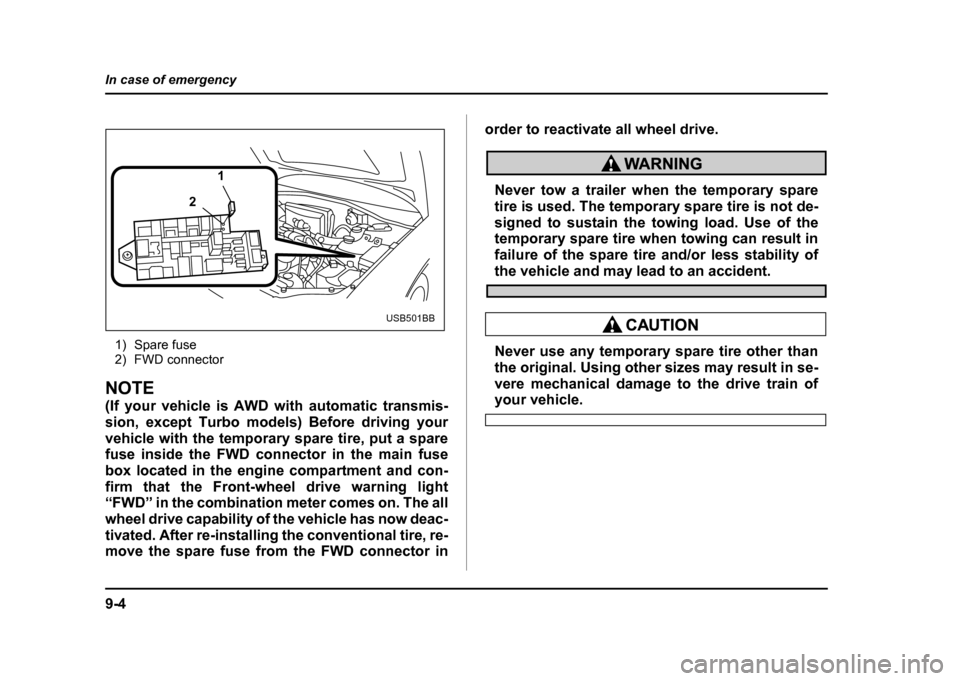
1) Spare fuse
2) FWD connector
NOTE
(If your vehicle is AWD with automatic transmis-
sion, except Turbo models) Before driving your
vehicle with the temporary spare tire, put a sparefuse inside the FWD connector in the main fuse
box located in the engine compartment and con-
firm that the Front-wheel drive warning light
“FWD” in the combination meter comes on. The all
wheel drive capability of the vehicle has now deac-
tivated. After re-installing the conventional tire, re-
move the spare fuse from the FWD connector in
order to reactivate all wheel drive.
Never tow a trailer when the temporary spare
tire is used. The temporary spare tire is not de-
signed to sustain the towing load. Use of the
temporary spare tire when towing can result in
failure of the spare tire and/or less stability of
the vehicle and may lead to an accident.
Never use any temporary spare tire other than
the original. Using other sizes may result in se-
vere mechanical damage to the drive train of
your vehicle.
1
2
USB501BB
Page 393 of 491
11 - 8
Maintenance and service
Engine compartment overview !
2.5 liter model
12 345 67
8
9
10
11
12
13
UGB505BB
1) Manual transmission oil level
gauge (MT) (page 11-28) or Dif-
ferential gear oil level gauge
(AT) (page 11-33)
2) Air cleaner element (page 11- 23)
3) Clutch fluid reservoir (page 11- 38)
4) Automatic transmission fluid lev-
el gauge (page 11-31)
5) Brake fluid reservoir (page 11-
37)
6) Windshield washer tank (page 11-54)
7) Fuse box (page 11-60)
8) Battery (page 11-58)
9) Engine oil filler cap (page 11-11)
10) Engine coolant reservoir (page 11-19)
11) Radiator cap (page 11-19)
12) Engine oil level gauge (page 11- 11)
13) Power steering fluid reservoir
(page 11-36)
Page 394 of 491
11 - 9
Maintenance and service
– CONTINUED –
!2.0 liter (Turbo) model
34 5 6 7
1
2
13 12 11 10 9 8
HGB005CB
1) Manual transmission oil level gauge (MT) (page 11-28) or Dif-
ferential gear oil level gauge
(AT) (page 11-33)
2) Air cleaner element (page 11- 23)
3) Clutch fluid reservoir (page 11- 38)
4) Automatic transmission fluid lev-
el gauge (page 11-31)
5) Brake fluid reservoir (page 11-
37)
6) Windshield washer tank (page 11-54)
7) Fuse box (page 11-60)
8) Battery (page 11-58)
9) Engine oil filler cap (page 11-11)
10) Engine coolant reservoir (page 11-19)
11) Engine oil level gauge (page 11-
11)
12) Radiator cap (page 11-19)
13) Power steering fluid reservoir
(page 11-36)
Page 395 of 491
11 - 1 0
Maintenance and service !
2.5 liter (Turbo) model
34 5 6
7
1
2
12 11 10 9 8
UGB070BB
1) Manual transmission oil level gauge (MT) (page 11-28)
2) Air cleaner element (page 11-
23)
3) Clutch fluid reservoir (page 11- 38)
4) Brake fluid reservoir (page 11- 37)
5) Windshield washer tank (page
11-54)
6) Fuse box (page 11-60)
7) Battery (page 11-58)
8) Engine oil filler cap (page 11-11)
9) Engine coolant reservoir (page
11-19)
10) Engine oil level gauge (page 11- 11)
11) Radiator cap (page 11-19)
12) Power steering fluid reservoir (page 11-36)
Page 445 of 491
11 - 6 0
Maintenance and service
Fuses
Never replace a fuse with one having a higher
rating or with material other than a fuse be-
cause serious damage or a fire could result.
The fuses are designed to melt during an overload to
prevent damage to the wiring harness and electrical
equipment. The fuses are located in two fuse boxes.
One is located under the instrument panel behind the
coin tray on the driver’s seat side. To remove the coin tray, open the cover and pull the
coin tray out.
UGB547BA
UGB550BA
Page 446 of 491
11 -6 1
Maintenance and service
– CONTINUED –
The other one is housed in the engine compartment. 1) Fuse puller
2) Spare fuse
The fuse puller and spare fuses are stored in the main
fuse box cover in the engine compartment.
HSB065BA
1
2
HSB066BB
Page 447 of 491
11 - 6 2
Maintenance and service
A) Good
B) Blown
If any lights, accessories or other electrical controls do
not operate, inspect the corresponding fuse. If a fuse
has blown, replace it.
1. Turn the ignition switch to the “LOCK” position and
turn off all electrical accessories.
2. Remove the cover.
3. Determine which fuse may be blown. The back side
of each fuse box cover and the “Fuses and circuits”
section in chapter 12 in this manual show the circuit for
each fuse. 1) Fuse puller
4. Pull out the fuse with the fuse puller.
5. Inspect the fuse. If it has blown, replace it with a
spare fuse of the same rating.
6. If the same fuse blows again, this indicates that its
system has a problem. Contact your SUBARU dealer for repairs.
AB
HSB067BB
1
HSB068BB