2004 SUBARU IMPREZA service indicator
[x] Cancel search: service indicatorPage 5 of 491

2
How to use this owner’s manual !Using your Owner’s manual
Before you operate your vehicle, carefully read this
manual. To protect yourself and extend the service life
of your vehicle, follow the instructions in this manual.
Failure to observe these instructions may result in se-
rious injury and damage to your vehicle.
This manual is composed of fourteen chapters. Each
chapter begins with a brief table of contents, so you
can usually tell at a glance if that chapter contains the
information you want.
Chapter 1: Seat, seatbelt and SRS airbags
This chapter informs you how to use the seat and seat-
belt and contains precautions for the SRS airbags.
Chapter 2: Keys and doors
This chapter informs you how to operate the keys,
locks and windows.
Chapter 3: Instruments and controls
This chapter informs you about the operation of instru-
ment panel indicators and how to use the instruments
and other switches.
Chapter 4: Climate Control
This chapter informs you how to operate the climate
control.
Chapter 5: Audio This chapter informs you how to operate your audio system.
Chapter 6: Interior equipment
This chapter informs you how to operate interior
equipment.
Chapter 7: Starting and operating
This chapter informs you how to start and operate your SUBARU.
Chapter 8: Driving tips
This chapter informs you how to drive your SUBARU
in various conditions and explains some safety tips on
driving.
Chapter 9: In case of emergency
This chapter informs you what to do if you have a prob-
lem while driving, such as a flat tire or engine over-
heating.
Chapter 10: Appearance care
This chapter informs you how to keep your SUBARU
looking good.
Chapter 11: Maintenance and service
This chapter informs you when you need to take your
SUBARU to the dealer for scheduled maintenance
and informs you how to keep your SUBARU running
properly.
Chapter 12: Specifications
This chapter informs you about dimension and capac-
ities of your SUBARU.
Page 100 of 491

1-73
Seat, seatbelt and SRS airbags
– CONTINUED –
"Airbag control module (including impact sensors)
" Frontal airbag module (Driver’s side)
" Frontal airbag module (Passenger’s side)
" Side airbag sensor (Driver’s side — if equipped)
" Side airbag sensor (Passenger’s side — if
equipped) " Side airbag module (Driver’s side — if equipped)
" Side airbag module (Passenger’s side — if
equipped)" Seatbelt pretensioner (Driver’s side)
" Seatbelt pretensioner (Passenger’s side)
" All related wiring
In the event of a malfunction indicated by any of follow-
ing, the vehicle should be taken promptly to your near-
est SUBARU dealer to have the system checked. Un-
less checked and repaired, the SRS airbags will not
function reliably: " Flashing or flickering of the indicator light.
" No illumination of the warning light when the ignition
switch is first turned to the “ON” position." Continuous illumination of the warning light.
" Illumination of the warning light while driving. !
SRS airbag system servicing
"When discarding an airbag module or scrap-
ping the entire car damaged by a collision, con-
sult your SUBARU dealer." The SRS airbag has no user-serviceable
parts. Do not use electrical test equipment on
any circuit related to the SRS airbag system.
For required servicing of the SRS airbag, see
your nearest SUBARU dealer. Tampering with
or disconnecting the system’s wiring could re-
sult in accidental inflation of the SRS airbag or
could make the system inoperative, which may
result in serious injury. The wiring harnesses of
the SRS airbag system are covered with yellow
insulation and system connectors are yellow
for easy identification.
If you need service or repair in areas listed be-
low, we recommend that you have an autho-
rized SUBARU dealer perform the work. The
SRS airbag control module, impact sensors
and airbag modules are stored in these areas.
Page 277 of 491

7-8
Starting and operating
inspection program or its contractors or licens-ees.
The EPA has issued regulations for inspecting the On-
Board Diagnostic (OBD) system as part of the state
emissions inspection. The OBD system is designed to
detect engine and transmission problems that might
cause vehicle emissions to exceed allowable limits.
These inspections apply to all 1996 model year and
newer passenger cars and light trucks. Several states
plus the District of Columbia have opted to start the
OBD system inspection prior to the required EPA reg-
ulation effective date of January 1, 2002. Other states
will add OBD system inspection in 2002. " The inspection of the OBD system consists of a vi-
sual operational check of the “ CHECK ENGINE” warn-
ing light/malfunction indicator lamp (MIL) and an ex-
amination of the OBD system with an electronic scan
tool while the engine is running." A vehicle passes
the OBD system inspection if
proper the “ CHECK ENGINE ” warning light/MIL illumi-
nation is observed, there is no stored diagnostic trou-
ble codes, and the OBD system readiness monitors
are complete. " A vehicle fails
the OBD inspection if the “ CHECK
ENGINE ” warning light/MIL is not properly operating or there is one or more diagnostic trouble codes stored
in vehicle’s computer with the “
CHECK ENGINE”
warning light/MIL illuminated. " A state emission inspection may reject (not pass or
fail) a vehicle if the number of OBD system readinessmonitors “ Not Ready ” is greater than three. Under this
condition, the vehicle operator should be instructed to
drive his/her vehicle for a few days to set the monitors
and return for an emission re-inspection. " Owners of rejected or failing vehicles should contact
their Subaru Dealer for service.
Page 387 of 491

11 - 2
Maintenance and service
Types of tires .................................................... 11-44
Tire inspection .................................................. 11-45
Tire pressures and wear .................................. 11-45
Wheel balance ................................................... 11-48
Wear indicators ................................................. 11-49
Tire rotation ....................................................... 11-50
Tire replacement ............................................... 11-50
Wheel replacement ........................................... 11-51
Wheel covers .................................................... 11-52
Aluminum wheels (If equipped) .................. 11-53
Intercooler water spray ................................ 11-53
Windshield washer fluid .............................. 11-54
Replacement of windshield wiper blades .. 11-55
Battery ........................................................... 11-58
Fuses ............................................................. 11-60
Main fuse ....................................................... 11-63
Installation of accessories .......................... 11-63
Replacing bulbs ............................................ 11-64 Headlights (U.S. spec. WRX-STi) .................... 11-66
Headlight (Except U.S. spec. WRX-STi) .......... 11-66
Front turn signal light bulbs ............................ 11-69
Parking light ...................................................... 11-70
Front fog light ................................................... 11-73
Rear combination lights ................................... 11-74
License plate light ............................................ 11-76
Dome light, map light and cargo area light .... 11-77
Trunk light ......................................................... 11-78
High mount stop light ...................................... 11-78
Page 427 of 491

11 - 4 2
Maintenance and service
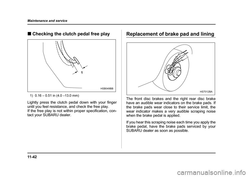
!
Checking the clutch pedal free play
1) 0.16 – 0.51 in (4.0 –13.0 mm)
Lightly press the clutch pedal down with your finger
until you feel resistance, and check the free play.
If the free play is not within proper specification, con-
tact your SUBARU dealer.Replacement of brake pad and lining
The front disc brakes and the right rear disc brake
have an audible wear indicators on the brake pads. If
the brake pads wear close to their service limit, the
wear indicator makes a very audible scraping noise
when the brake pedal is applied.
If you hear this scraping noise each time you apply the
brake pedal, have the brake pads serviced by your
SUBARU dealer as soon as possible.
1
HSB049BBHS7012BA
Page 434 of 491

11 -4 9
Maintenance and service
– CONTINUED –
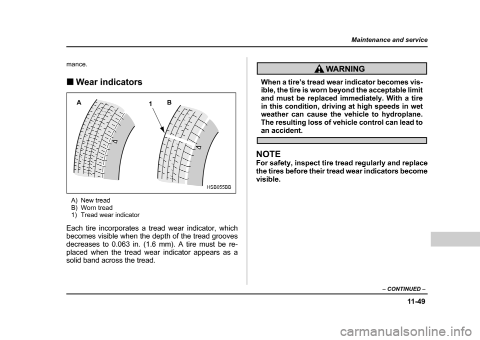
mance. !Wear indicators
A) New tread
B) Worn tread
1) Tread wear indicator
Each tire incorporates a tread wear indicator, which
becomes visible when the depth of the tread grooves
decreases to 0.063 in. (1.6 mm). A tire must be re-
placed when the tread wear indicator appears as a
solid band across the tread.
When a tire’s tread wear indicator becomes vis-
ible, the tire is worn beyond the acceptable limit
and must be replaced immediately. With a tire
in this condition, driving at high speeds in wet
weather can cause the vehicle to hydroplane.
The resulting loss of vehicle control can lead to
an accident.
NOTE
For safety, inspect tire tread regularly and replace
the tires before their tread wear indicators become visible.
A 1B
HSB055BB