Page 21 of 491
18
!
Instrument panel
12345 6
7
8
9
11
12
13
14
15
16 10
UGF056BB
1) Door locks (page 2-3)
2) Light control lever (page 3-29)
3) Combination meter (page 3-15)
4) Wiper control lever (page 3-35)
5) Hazard warning flasher switch
(page 3-6)
6) Audio (page 5-1)
7) Gear shift lever (MT) (page 7- 15)/Selector lever (AT) (page 7-
21)
8) Outside mirror switch (page 3-
48)
9) Climate control (page 4-1)
10) Cruise control (page 7-37)
11) Horn (page 3-50)
12) SRS airbag (page 1-52)
13) Tilt steering (page 3-49)
14) Fuse box (page 11-60)
15) Hood lock release (page 11-5)
16) Power window (page 2-22)
Page 146 of 491

3-9
Instruments and controls
– CONTINUED –
To set the trip meter to zero, select the A trip or B trip
meter by pushing the knob and keep the knob pushed for more than 2 seconds.
To ensure safety, do not attempt to change the
function of the indicator during driving, as an
accident could result.
NOTE
If the connection between the combination meter
and battery is broken for any reason such as vehi-
cle maintenance or fuse replacement, the data re-
corded on the trip meter will be lost. !Tachometer
The tachometer shows the engine speed in thousands
of revolutions per minute.
Do not operate the engine with the pointer of the tachometer in the red zone. In this range, fuel injection will be cut by the engine control
module to protect the engine from overrevving.
The engine will resume running normally after
the engine speed is reduced below the red
zone.
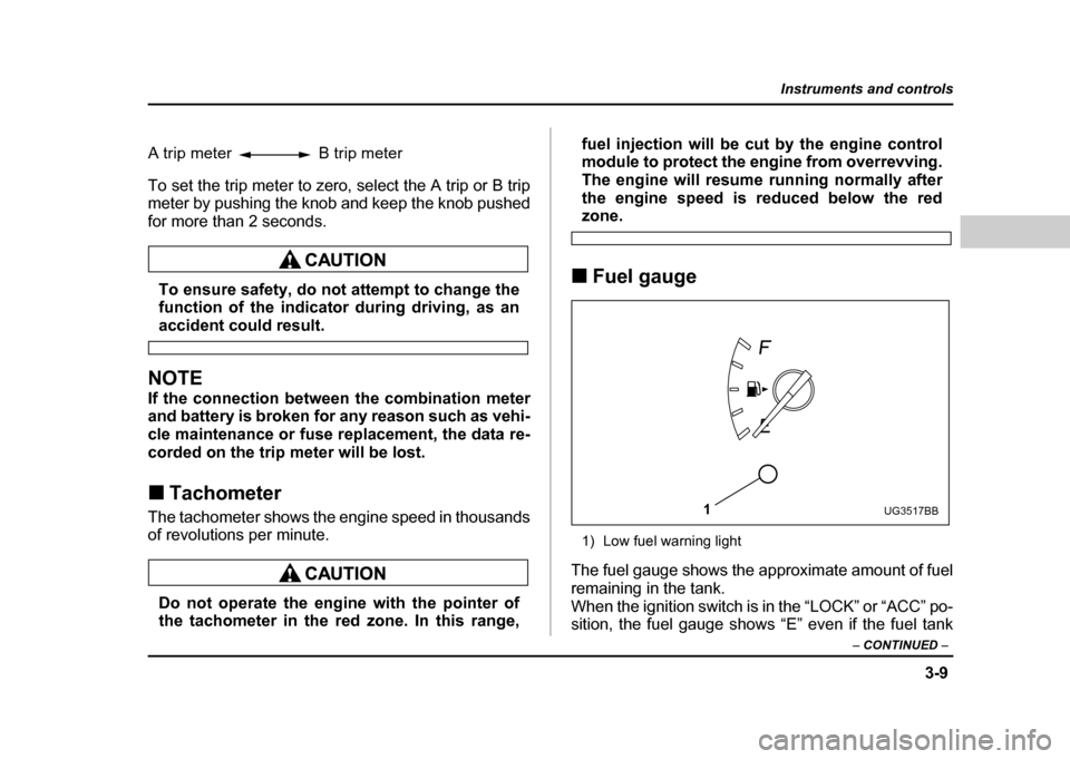
! Fuel gauge
1) Low fuel warning light
The fuel gauge shows the approximate amount of fuel
remaining in the tank.
When the ignition switch is in the “LOCK” or “ACC” po-
sition, the fuel gauge shows “E” even if the fuel tank
A trip meter B trip meter
1UG3517BB
Page 153 of 491

3-16
Instruments and controls
To set the trip meter to zero, select the A trip or B trip
meter by pushing the knob and keep the knob pushed
for more than 2 seconds.
To ensure safety, do not attempt to change the
function of the indicator during driving, as an
accident could result.
NOTE
If the connection between the combination meter
and battery is broken for any reason such as vehi-
cle maintenance or fuse replacement, the data re-
corded on the trip meter will be lost. !
Tachometer
The tachometer shows the engine speed in thousands
of revolutions per minute.
Do not operate the engine with the pointer of
the tachometer in the red zone. In this range, fuel injection will be cut by the engine control
module to protect the engine from overrevving.
The engine will resume running normally after
the engine speed is reduced below the red
zone.
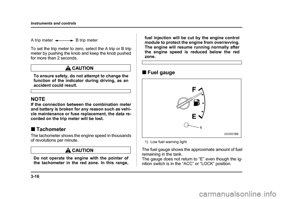
! Fuel gauge
1) Low fuel warning light
The fuel gauge shows the approximate amount of fuel
remaining in the tank.
The gauge does not return to “E” even though the ig-
nition switch is in the “ACC” or “LOCK” position.
A trip meter B trip meter
1
UG3501BB
Page 355 of 491

9-4
In case of emergency
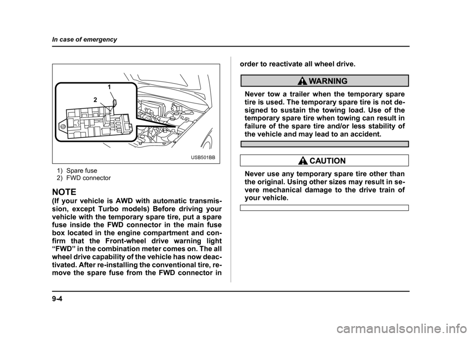
1) Spare fuse
2) FWD connector
NOTE
(If your vehicle is AWD with automatic transmis-
sion, except Turbo models) Before driving your
vehicle with the temporary spare tire, put a sparefuse inside the FWD connector in the main fuse
box located in the engine compartment and con-
firm that the Front-wheel drive warning light
“FWD” in the combination meter comes on. The all
wheel drive capability of the vehicle has now deac-
tivated. After re-installing the conventional tire, re-
move the spare fuse from the FWD connector in
order to reactivate all wheel drive.
Never tow a trailer when the temporary spare
tire is used. The temporary spare tire is not de-
signed to sustain the towing load. Use of the
temporary spare tire when towing can result in
failure of the spare tire and/or less stability of
the vehicle and may lead to an accident.
Never use any temporary spare tire other than
the original. Using other sizes may result in se-
vere mechanical damage to the drive train of
your vehicle.
1
2
USB501BB
Page 387 of 491

11 - 2
Maintenance and service
Types of tires .................................................... 11-44
Tire inspection .................................................. 11-45
Tire pressures and wear .................................. 11-45
Wheel balance ................................................... 11-48
Wear indicators ................................................. 11-49
Tire rotation ....................................................... 11-50
Tire replacement ............................................... 11-50
Wheel replacement ........................................... 11-51
Wheel covers .................................................... 11-52
Aluminum wheels (If equipped) .................. 11-53
Intercooler water spray ................................ 11-53
Windshield washer fluid .............................. 11-54
Replacement of windshield wiper blades .. 11-55
Battery ........................................................... 11-58
Fuses ............................................................. 11-60
Main fuse ....................................................... 11-63
Installation of accessories .......................... 11-63
Replacing bulbs ............................................ 11-64 Headlights (U.S. spec. WRX-STi) .................... 11-66
Headlight (Except U.S. spec. WRX-STi) .......... 11-66
Front turn signal light bulbs ............................ 11-69
Parking light ...................................................... 11-70
Front fog light ................................................... 11-73
Rear combination lights ................................... 11-74
License plate light ............................................ 11-76
Dome light, map light and cargo area light .... 11-77
Trunk light ......................................................... 11-78
High mount stop light ...................................... 11-78
Page 393 of 491
11 - 8
Maintenance and service
Engine compartment overview !
2.5 liter model
12 345 67
8
9
10
11
12
13
UGB505BB
1) Manual transmission oil level
gauge (MT) (page 11-28) or Dif-
ferential gear oil level gauge
(AT) (page 11-33)
2) Air cleaner element (page 11- 23)
3) Clutch fluid reservoir (page 11- 38)
4) Automatic transmission fluid lev-
el gauge (page 11-31)
5) Brake fluid reservoir (page 11-
37)
6) Windshield washer tank (page 11-54)
7) Fuse box (page 11-60)
8) Battery (page 11-58)
9) Engine oil filler cap (page 11-11)
10) Engine coolant reservoir (page 11-19)
11) Radiator cap (page 11-19)
12) Engine oil level gauge (page 11- 11)
13) Power steering fluid reservoir
(page 11-36)
Page 394 of 491
11 - 9
Maintenance and service
– CONTINUED –
!2.0 liter (Turbo) model
34 5 6 7
1
2
13 12 11 10 9 8
HGB005CB
1) Manual transmission oil level gauge (MT) (page 11-28) or Dif-
ferential gear oil level gauge
(AT) (page 11-33)
2) Air cleaner element (page 11- 23)
3) Clutch fluid reservoir (page 11- 38)
4) Automatic transmission fluid lev-
el gauge (page 11-31)
5) Brake fluid reservoir (page 11-
37)
6) Windshield washer tank (page 11-54)
7) Fuse box (page 11-60)
8) Battery (page 11-58)
9) Engine oil filler cap (page 11-11)
10) Engine coolant reservoir (page 11-19)
11) Engine oil level gauge (page 11-
11)
12) Radiator cap (page 11-19)
13) Power steering fluid reservoir
(page 11-36)
Page 395 of 491
11 - 1 0
Maintenance and service !
2.5 liter (Turbo) model
34 5 6
7
1
2
12 11 10 9 8
UGB070BB
1) Manual transmission oil level gauge (MT) (page 11-28)
2) Air cleaner element (page 11-
23)
3) Clutch fluid reservoir (page 11- 38)
4) Brake fluid reservoir (page 11- 37)
5) Windshield washer tank (page
11-54)
6) Fuse box (page 11-60)
7) Battery (page 11-58)
8) Engine oil filler cap (page 11-11)
9) Engine coolant reservoir (page
11-19)
10) Engine oil level gauge (page 11- 11)
11) Radiator cap (page 11-19)
12) Power steering fluid reservoir (page 11-36)