2004 PONTIAC BONNEVILLE engine
[x] Cancel search: enginePage 113 of 446

Programming the HomeLink®
Transmitter
Do not use the HomeLink®Transmitter with any garage
door opener that does not have the “stop and reverse”
feature. This includes any garage door opener model
manufactured before April 1, 1982. If you have a newer
garage door opener with rolling codes, please be
sure to follow steps 6 through 8 to complete the
programming of your HomeLink
®Transmitter.
Read the instructions completely before attempting to
program the HomeLink
®Transmitter. Because of
the steps involved, it may be helpful to have another
person available to assist you in programming the
transmitter.
Keep the original transmitter for use in other vehicles as
well as for future HomeLink
®programming. It is also
recommended that upon the sale of the vehicle,
the programmed HomeLink
®buttons should be erased
for security purposes. Refer to “Erasing HomeLink®
Buttons” or, for assistance, contact HomeLink®on the
internet at: www.homelink.com or by calling
1-800-355-3515.Be sure that people and objects are clear of the garage
door or gate operator you are programming. When
programming a garage door, it is advised to park outside
of the garage.
It is recommended that a new battery be installed in
your hand-held transmitter for quicker and more
accurate transmission of the radio frequency.
Your vehicle’s engine should be turned off while
programming the transmitter. Follow these steps to
program up to three channels:
1. Press and hold down the two outside buttons,
releasing only when the indicator light begins to
�ash, after 20 seconds. Do not hold down the
buttons for longer than 30 seconds and do not
repeat this step to program a second and/or third
transmitter to the remaining two HomeLink
®buttons.
2. Position the end of your hand-held transmitter about
1 to 3 inches (3 to 8 cm) away from the HomeLink
®
buttons while keeping the indicator light in view.
3. Simultaneously press and hold both the desired
button on HomeLink
®and the hand-held transmitter
button. Do not release the buttons until Step 4
has been completed.
Some entry gates and garage door openers may
require you to substitute Step 3 with the procedure
noted in “Gate Operator and Canadian
Programming” later in this section.
2-45
Page 121 of 446
Instrument Panel Overview...............................3-4
Hazard Warning Flashers................................3-6
Other Warning Devices...................................3-6
Horn.............................................................3-7
Tilt Wheel.....................................................3-7
Turn Signal/Multifunction Lever.........................3-7
Windshield Wiper Lever.................................3-13
Exterior Lamps.............................................3-14
Interior Lamps..............................................3-18
Head-Up Display (HUD).................................3-22
Accessory Power Outlets...............................3-25
Ashtrays and Cigarette Lighter........................3-26
Climate Controls............................................3-27
Climate Control System.................................3-27
Automatic Climate Control System...................3-29
Outlet Adjustment.........................................3-34
Climate Controls Personalization.....................3-35
Warning Lights, Gages, and Indicators............3-36
Instrument Panel Cluster................................3-37
Speedometer and Odometer...........................3-39
Tachometer.................................................3-40
Safety Belt Reminder Light.............................3-40
Air Bag Readiness Light................................3-41
Voltmeter Gage............................................3-42Brake System Warning Light..........................3-42
Anti-Lock Brake System Warning Light.............3-44
Traction Control System (TCS) Warning Light......3-45
Low Traction Active Light...............................3-46
Engine Coolant Temperature Gage..................3-47
Tire Pressure Light.......................................3-48
Malfunction Indicator Lamp.............................3-48
Oil Pressure Gage........................................3-52
Check Oil Level Light....................................3-53
Security Light...............................................3-53
Low Washer Fluid Warning Light.....................3-53
Check Gages Warning Light...........................3-54
Door Ajar Light.............................................3-54
Trunk Ajar Light............................................3-55
Service Vehicle Soon Light............................3-55
Fuel Gage...................................................3-56
Systems Monitor............................................3-57
Driver Information Center (DIC).......................3-58
DIC Controls and Displays.............................3-58
DIC Warnings and Messages.........................3-61
Driver Identi�er DIC Display...........................3-63
DIC Vehicle Personalization............................3-64
Secondary Information Center (SIC).................3-70
Electronic Compass......................................3-70
Section 3 Instrument Panel
3-1
Page 142 of 446
Battery Load Management
The battery load management feature is designed to
monitor the vehicle’s electrical load and determine when
the battery is in a heavy discharge condition. During
times of high electrical loading, the engine may idle at
higher revolutions per minute (RPM) than normal to make
sure the battery charges. High electrical loads may occur
when several of the following are on: headlamps, high
beams, fog lamps, rear window defogger, fan on high
speed, heated seats and engine cooling fans.
If your vehicle’s battery remains in a heavy discharge
condition for a long period of time, the fan, rear
defogger, heated seats and heated mirrors will be
disabled and the DIC will display BATTERY SAVER
ACTIVE. This can happen either under long periods of
idling or low speed driving with high electrical loading,
or in the event of a charging system fault.
Monitor the battery voltage when in the BATTERY
SAVER ACTIVE mode.
If the voltmeter remains in the shaded area (below
11 volts) when driving then have the charging
system serviced immediately.
If the voltage increases above 12 volts then the
battery needs to be recharged. Try driving on
the highway with as few electrical accessories on
as possible.
Head-Up Display (HUD)
{CAUTION:
If the HUD image is too bright, or too high in
your �eld of view, it may take you more time to
see things you need to see when it is dark
outside. Be sure to keep the HUD image dim
and placed low in your �eld of view.
If you have the optional Head-Up Display (HUD), you
can see some of the driver information also available on
your instrument panel cluster. The information may
be displayed in English or metric units and appears as a
re�ection on the windshield. The HUD shows the
following:
Speedometer Reading
Turn Signal Indicators
High-beam Indicator Symbol
CHECK GAGES Message (for low oil pressure,
high coolant temperature, low oil level, high/low
battery, brake, ABS and air bag)
Low Fuel Warning Symbol
Radio Frequency and Playback Mode (with the
exception of the XM™ radio)
3-22
Page 143 of 446
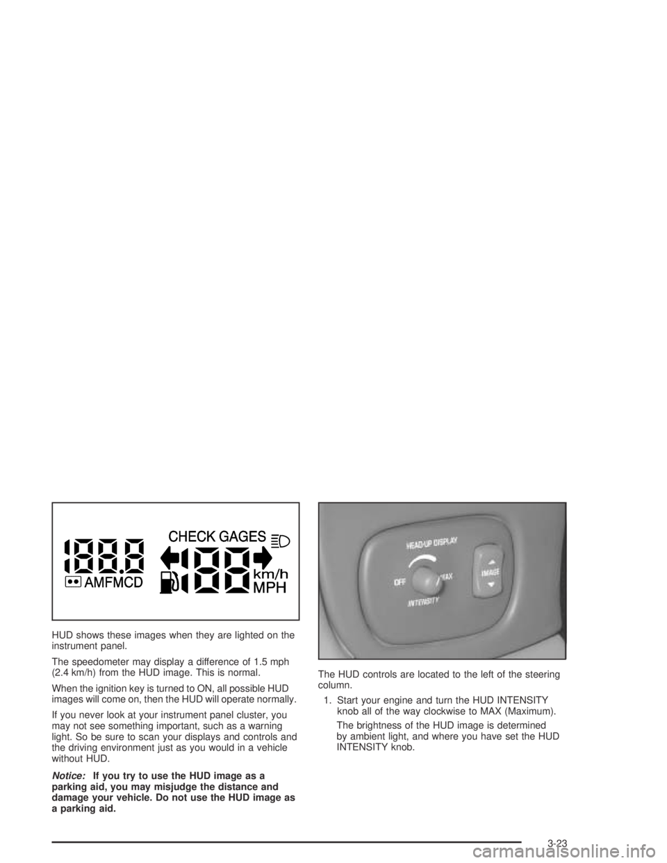
HUD shows these images when they are lighted on the
instrument panel.
The speedometer may display a difference of 1.5 mph
(2.4 km/h) from the HUD image. This is normal.
When the ignition key is turned to ON, all possible HUD
images will come on, then the HUD will operate normally.
If you never look at your instrument panel cluster, you
may not see something important, such as a warning
light. So be sure to scan your displays and controls and
the driving environment just as you would in a vehicle
without HUD.
Notice:If you try to use the HUD image as a
parking aid, you may misjudge the distance and
damage your vehicle. Do not use the HUD image as
a parking aid.The HUD controls are located to the left of the steering
column.
1. Start your engine and turn the HUD INTENSITY
knob all of the way clockwise to MAX (Maximum).
The brightness of the HUD image is determined
by ambient light, and where you have set the HUD
INTENSITY knob.
3-23
Page 145 of 446
Accessory Power Outlets
With the accessory power outlet you can plug in
auxiliary electrical equipment such as a cellular
telephone or CB radio.
If your vehicle has a front console, the accessory power
outlet (12-volt ) is located at the rear of the front
console. If your vehicle has a �oor console, the outlet is
located at the rear of the �oor console.
To use the outlet, remove the protective cap which
covers it. When not using it, always cover the outlet with
the protective cap.
The accessory power outlet will only operate when the
ignition key is in ON and for 10 minutes after turning
the ignition OFF. If you would like the accessory power
outlet to operate regardless of ignition position, and
for extended periods of time, see “Engine Compartment
Fuse Block” underFuses and Circuit Breakers on
page 5-101or see your dealer for more information.
Notice:Leaving electrical equipment on for
extended periods will drain the battery. Always turn
off electrical equipment when not in use and do
not plug in equipment that exceeds the maximum
amperage rating.Certain electrical accessories may not be compatible
with the accessory power outlet and could result
in blown vehicle or adapter fuses. If you experience a
problem, see your dealer for additional information
on accessory power outlets.
Notice:Adding any electrical equipment to your
vehicle may damage it or keep other components
from working as they should. The repairs would not
be covered by your warranty. Check with your
dealer before adding electrical equipment.
When adding electrical equipment, be sure to follow the
proper installation instructions included with the
equipment.
Notice:Improper use of the power outlet can cause
damage not covered by your warranty. Do not
hang any type of accessory or accessory bracket
from the plug because the power outlets are
designed for accessory power plugs only.
3-25
Page 146 of 446

Ashtrays and Cigarette Lighter
Push down on the cover to reveal the front ashtray. To
clean the ashtray, lift it out by pulling on the �nger
holes on each side.
On models without a console, an ashtray is located
underneath the instrument panel. To clean the ashtray,
lift it out by pulling up on the tabs on either side. It
snaps back into place.
To open a rear ashtray, lift the cover.
Notice:If you put papers or other �ammable items
in the ashtray, hot cigarettes or other smoking
materials could ignite them and possibly damage
your vehicle. Never put �ammable items in the
ashtray.
The cigarette lighter is located next to the storage tray.
To use a lighter, just push the center in all the way
and let it go. When it is ready, the center will pop back
out by itself. Pull out the entire unit to use it.Notice:Holding a cigarette lighter in while it is
heating will not allow the lighter to back away from
the heating element when it is hot. Damage from
overheating may occur to the lighter or heating
element, or a fuse could be blown. Do not hold a
cigarette lighter in while it is heating.
The cigarette lighter will only operate when the ignition
key is in ON and for 10 minutes after turning the
ignition OFF. If you would like the lighter to operate
regardless of ignition position, and for extended periods
of time, see “Engine Compartment Fuse Block” under
Fuses and Circuit Breakers on page 5-101or see
your dealer.
3-26
Page 148 of 446
#A/C (Air Conditioning):Press this button to turn
the air conditioning compressor on and off. When A/C is
pressed, an indicator light in the button will come on
to let you know that air conditioning is activated. If your
climate control system is off, you may also turn it
back on in vent mode by selecting the A/C button.
On hot days, open the windows to let hot inside
air escape; then close them. This helps to reduce the
time it takes for your vehicle to cool down. It also helps
the system to operate more efficiently.
For quick cool down on hot days, do the following:
1. Select the vent mode.
2. Select the recirculation mode.
3. Select A/C.
4. Select the coolest temperature.
5. Select the highest fan speed.
Using these settings together for long periods of time
may cause the air inside of your vehicle to become too
dry. To prevent this from happening, after the air in
your vehicle has cooled, turn the recirculation mode off.
The air conditioning system removes moisture from
the air, so you may sometimes notice a small amount of
water dripping underneath your vehicle while idling or
after turning off the engine. This is normal.Defogging and Defrosting
Fog on the inside of windows is a result of high humidity
(moisture) condensing on the cool window glass. This
can be minimized if the climate control system is used
properly. There are two modes to clear fog or frost from
your windshield. Use the defog mode to clear the
windows of fog or moisture and warm the passengers.
Use the defrost mode to remove fog or frost from the
windshield more quickly.
Press one of the available mode buttons to select the
defog or defrost mode.
-(Defog):This mode directs most of the air to the
windshield and the �oor outlets. A small amount of air is
also directed to the outboard outlets (for the side
windows). When you select this mode, the system turns
off recirculation and runs the air conditioning compressor
unless the outside temperature is at or below freezing.
The recirculation mode cannot be selected while in the
defog mode.
3-28
Page 149 of 446

0FRONT (Defrost):Pressing this button directs
most of the air to the windshield and the outboard outlets
(for the side windows), with some air directed to the
�oor outlets. When you select this mode, the system
turns off recirculation and runs the air conditioning
compressor unless the outside temperature is at
or below freezing. The recirculation mode cannot be
selected while in the FRONT defrost mode. Do not drive
the vehicle until all windows are clear.
Rear Window Defogger
The rear window defogger uses a warming grid to
remove fog or frost from the rear window.
=REAR:Press this button to turn the rear window
defogger on or off. Be sure to clear as much snow from
the rear window as possible.
The rear window defogger will turn off about 10 minutes
after the button is pressed. If turned on again, the
defogger will only run for about �ve minutes before
turning off. If you maintain a speed above 30 mph (48
km/h), the rear defogger will not turn off automatically to
help keep the rear glass clear. The defogger can also
be turned off by pressing the button again or by turning
off the engine.If your vehicle has outside heated mirrors, the mirrors
will heat to help clear fog or frost from the surface of the
mirror when the rear window defogger button is
pressed.
Notice:Using a razor blade or sharp object to clear
the inside rear window may damage the rear
window defogger. Repairs would not be covered by
your warranty. Do not clear the inside of the rear
window with sharp objects.
Automatic Climate Control System
With this system you can control the heating, cooling
and ventilation for your vehicle.
3-29