2004 NISSAN TERRANO Heater
[x] Cancel search: HeaterPage 2 of 1833

Edition: February 2004
Release: February 2004 (01)
Publication No.: SM4E00-1R20E0E
Reference No.: 7711347141
GENERAL INFORMATIONGI
MAINTENANCEMA
ENGINE MECHANICALEM
ENGINE LUBRICATION &
COOLING SYSTEMSLC
ENGINE CONTROL SYSTEMEC
ACCELERATOR CONTROL,
FUEL & EXHAUST SYSTEMFE
CLUTCHCL
MANUAL TRANSMISSIONMT
AUTOMATIC TRANSMISSIONAT
TRANSFERTF
PROPELLER SHAFT &
DIFFERENTIAL CARRIERPD
FRONT AXLE & FRONT SUSPENSIONFA
REAR AXLE & REAR SUSPENSIONRA
BRAKE SYSTEMBR
STEERING SYSTEMST
RESTRAINT SYSTEMRS
BODY & TRIMBT
HEATER & AIR CONDITIONERHA
STARTING & CHARGING SYSTEMSSC
ELECTRICAL SYSTEMEL
ALPHABETICAL INDEXIDX
TERRANO
MODEL R20 SERIES
NISSAN EUROPE S.A.S.
2004 NISSAN EUROPE S.A.S.
Produced in The Netherlands
Not to be reproduced in whole or in part
without the prior written permission of
Nissan Europe S.A.S., Paris, France.
QUICK REFERENCE INDEX
http://vnx.su/
Page 9 of 1833
Precautions for Fuel
DIESEL ENGINE*:
Diesel fuel of at least 50 cetane for ZD30DDTi engine.
* If two types of diesel fuel are available, use summer or winterfuel properly according to the following temperature conditions.
I Above þ7ÉC (20ÉF) ... Summer type diesel fuel.
I Below þ7ÉC (20ÉF) ... Winter type diesel fuel.
CAUTION:
I Do not use home heating oil, gasoline, or other alternate
fuels in your diesel engine. The use of those can cause
engine damage.
I Do not use summer fuel at temperature below þ7ÉC (20ÉF).
The cold temperature will cause wax to form in the fuel. As
a result, it may prevent the engine from running smoothly.
I Do not add gasoline or other alternate fuels to diesel fuel.
Precautions for Engine Oils
Prolonged and repeated contact with mineral oil will result in the
removal of natural fats from the skin, leading to dryness, irritation
and dermatitis. In addition, used engine oil contains potentially
harmful contaminants which may cause skin cancer. Adequate
means of skin protection and washing facilities must be provided.
HEALTH PROTECTION PRECAUTIONS
1. Avoid prolonged and repeated contact with oils, particularly
used engine oils.
2. Wear protective clothing, including impervious gloves where practicable.
3. Do not put oily rags in pockets.
4. Avoid contaminating clothes, particularly underwear, with oil.
5. Heavily soiled clothing and oil-impregnated footwear should not be worn. Overalls must be cleaned regularly.
6. First Aid treatment should be obtained immediately for open cuts and wounds.
7. Use barrier creams, applying them before each work period, to help the removal of oil from the skin.
8. Wash with soap and water to ensure all oil is removed (skin cleansers and nail brushes will help). Preparations containing
lanolin replace the natural skin oils which have been removed.
9. Do not use petrol, kerosine, diesel fuel, gas oil, thinners or sol- vents for cleaning skin.
10. If skin disorders develop, obtain medical advice without delay.
11. Where practicable, degrease components prior to handling.
12. Where there is a risk of eye contact, eye protection should be worn, for example, chemical goggles or face shields; in addition
an eye wash facility should be provided.
(For the United Kingdom, see also HSE Cautionary Notice SHW
397 ªEffects of Mineral Oil on the Skinº.)
ENVIRONMENTAL PROTECTION PRECAUTIONS
Burning used engine oil in small space heaters or boilers can be
recommended only for units of approved design. The heating sys-
tem must meet the requirements of HM Inspectorate of Pollution for
small burners of less than 0.4 MW. If in doubt check with the
appropriate local authority and/or manufacturer of the approved
appliance.
PRECAUTIONS
GI-6
http://vnx.su/
Page 37 of 1833

ISO 15031-2 Terminology List
All emission related terms used in this publication in accordance with ISO 15031-2 are listed. Accordingly, new
terms, new acronyms/abbreviations and old terms are listed in the following chart.
***: Not applicable
NEW TERMNEW ACRONYM/
ABBREVIATION OLD TERM
Air cleaner ACL Air cleaner
Barometric pressure BARO
Barometric pressure sensor-BCDD BAROS-BCDD BCDD
Camshaft position CMP ***
Camshaft position sensor CMPS Crank angle sensor
Carburetor CARB Carburetor
Charge air cooler CAC Intercooler
Closed loop CL Closed loop
Closed throttle position switch CTP switch Idle switch
Clutch pedal position switch CPP switch Clutch switch
Continuous fuel injection system CFI system ***
Continuous trap oxidizer system CTOX system ***
Crankshaft position CKP ***
Crankshaft position sensor CKPS ***
Data link connector DLC ***
Data link connector for CONSULT DLC for CONSULT Diagnostic connector for CONSULT
Diagnostic test mode DTM Diagnostic mode
Diagnostic test mode selector DTM selector Diagnostic mode selector
Diagnostic test mode I DTM I Mode I
Diagnostic test mode II DTM II Mode II
Diagnostic trouble code DTC Malfunction code
Direct fuel injection system DFI system ***
Distributor ignition system DI system Ignition timing control
Early fuel evaporation-mixture heater EFE-mixture heater Mixture heater
Early fuel evaporation system EFE system Mixture heater control
Electrically erasable programmable read only
memory EEPROM ***
Electronic ignition system EI system Ignition timing control
Engine control module ECM ECCS control unit
Engine coolant temperature ECT Engine temperature
Engine coolant temperature sensor ECTS Engine temperature sensor
Engine modification EM ***
Engine speed RPM Engine speed
Erasable programmable read only memory EPROM ***
Evaporative emission system EVAP system Evaporative emission control system
Exhaust gas recirculation valve EGR valve EGR valve
Exhaust gas recirculation control-BPT valve EGRC-BPT valve BPT valve
Exhaust gas recirculation control-solenoid valve EGRC-solenoid valve EGR control solenoid valve
ISO 15031-2 TERMINOLOGY LIST
GI-34
http://vnx.su/
Page 63 of 1833
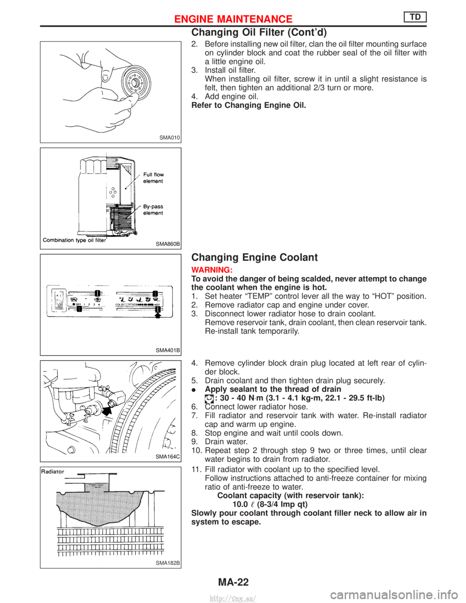
2. Before installing new oil filter, clan the oil filter mounting surfaceon cylinder block and coat the rubber seal of the oil filter with
a little engine oil.
3. Install oil filter. When installing oil filter, screw it in until a slight resistance is
felt, then tighten an additional 2/3 turn or more.
4. Add engine oil.
Refer to Changing Engine Oil.
Changing Engine Coolant
WARNING:
To avoid the danger of being scalded, never attempt to change
the coolant when the engine is hot.
1. Set heater ªTEMPº control lever all the way to ªHOTº position.
2. Remove radiator cap and engine under cover.
3. Disconnect lower radiator hose to drain coolant. Remove reservoir tank, drain coolant, then clean reservoir tank.
Re-install tank temporarily.
4. Remove cylinder block drain plug located at left rear of cylin- der block.
5. Drain coolant and then tighten drain plug securely.
I Apply sealant to the thread of drain
:30-40N ×m (3.1 - 4.1 kg-m, 22.1 - 29.5 ft-lb)
6. Connect lower radiator hose.
7. Fill radiator and reservoir tank with water. Re-install radiator cap and warm up engine.
8. Stop engine and wait until cools down.
9. Drain water.
10. Repeat step 2 through step 9 two or three times, until clear water begins to drain from radiator.
11. Fill radiator with coolant up to the specified level. Follow instructions attached to anti-freeze container for mixing
ratio of anti-freeze to water.Coolant capacity (with reservoir tank): 10.0 (8-3/4 Imp qt)
Slowly pour coolant through coolant filler neck to allow air in
system to escape.
SMA010
SMA860B
SMA401B
SMA164C
SMA182B
ENGINE MAINTENANCETD
Changing Oil Filter (Cont'd)
MA-22
http://vnx.su/
Page 67 of 1833

Checking Idle Speed
Preparation
1. Make sure that injection timing is correct.
2. Make sure that injection nozzle are in good condition.
3. Make sure that the following parts are in good condition.
IAir cleaner clogging
I Glow system
I Engine oil and coolant levels
I Valve clearance
I Air intake system (Oil filler cap, oil level gauge, etc.)
4. Set shift lever in ªNeutralº position. Engage parking brake and lock both front and rear wheels with wheel chocks.
5. Turn off air conditioner, lights and accessories.
I Warm up engine until water temperature indicator points to middle of gauge.
I Lights, heater fan and all accessories are off.
I Attach tachometer's pick-up to No. 1 fuel injection tube.
In order to take accurate reading of engine rpm, remove clamps that secure No. 1 fuel injection tube.
Start engine.
SMA406B
SMA021A
Run engine at about 2,000 rpm for
about 2 minutes under no-load.
Run engine for one minute at idle
speed.F
Check idle speed.
---------------------------------------------------------------------------------------------------------------------------------------------------------------------------------------------------------------------------------- IDLE SPEED: 700+ 50 rpm
OK
ENG Adjust idle speed by turning idle speed adjust-
ing screw.
EMA049
END
I
Race engine two or three times and allow engine to return to idle speed. If idle speed is not within
the specified range, check acceleration linkage for binding and correct it if necessary.
H
H
H
H
H
ENGINE MAINTENANCETD
MA-26
http://vnx.su/
Page 72 of 1833
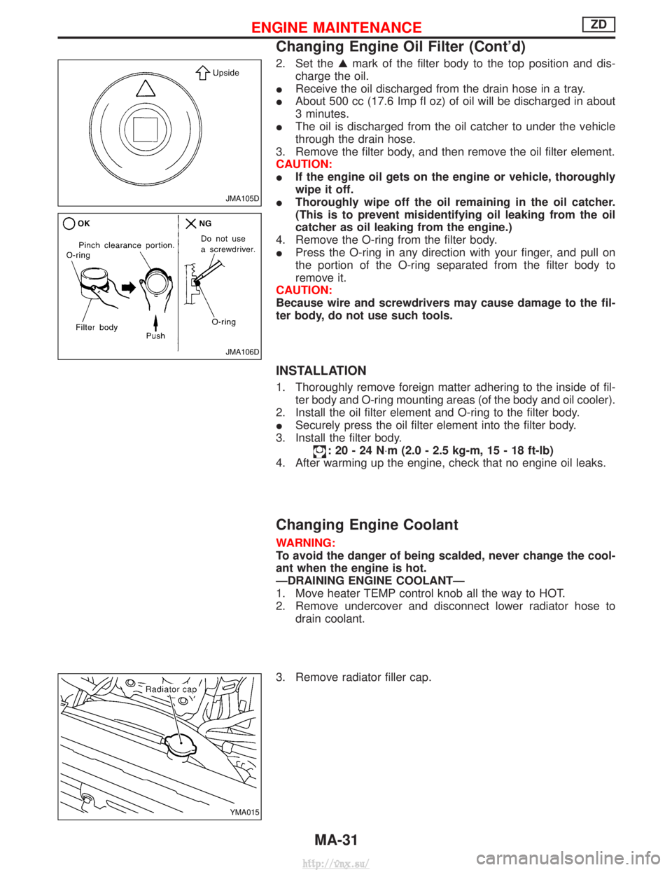
2. Set theGmark of the filter body to the top position and dis-
charge the oil.
I Receive the oil discharged from the drain hose in a tray.
I About 500 cc (17.6 Imp fl oz) of oil will be discharged in about
3 minutes.
I The oil is discharged from the oil catcher to under the vehicle
through the drain hose.
3. Remove the filter body, and then remove the oil filter element.
CAUTION:
I If the engine oil gets on the engine or vehicle, thoroughly
wipe it off.
I Thoroughly wipe off the oil remaining in the oil catcher.
(This is to prevent misidentifying oil leaking from the oil
catcher as oil leaking from the engine.)
4. Remove the O-ring from the filter body.
I Press the O-ring in any direction with your finger, and pull on
the portion of the O-ring separated from the filter body to
remove it.
CAUTION:
Because wire and screwdrivers may cause damage to the fil-
ter body, do not use such tools.
INSTALLATION
1. Thoroughly remove foreign matter adhering to the inside of fil- ter body and O-ring mounting areas (of the body and oil cooler).
2. Install the oil filter element and O-ring to the filter body.
I Securely press the oil filter element into the filter body.
3. Install the filter body.
:20-24N ×m (2.0 - 2.5 kg-m, 15 - 18 ft-lb)
4. After warming up the engine, check that no engine oil leaks.
Changing Engine Coolant
WARNING:
To avoid the danger of being scalded, never change the cool-
ant when the engine is hot.
ÐDRAINING ENGINE COOLANTÐ
1. Move heater TEMP control knob all the way to HOT.
2. Remove undercover and disconnect lower radiator hose to drain coolant.
3. Remove radiator filler cap.
JMA105D
JMA106D
YMA015
ENGINE MAINTENANCEZD
Changing Engine Oil Filter (Cont'd)
MA-31
http://vnx.su/
Page 73 of 1833
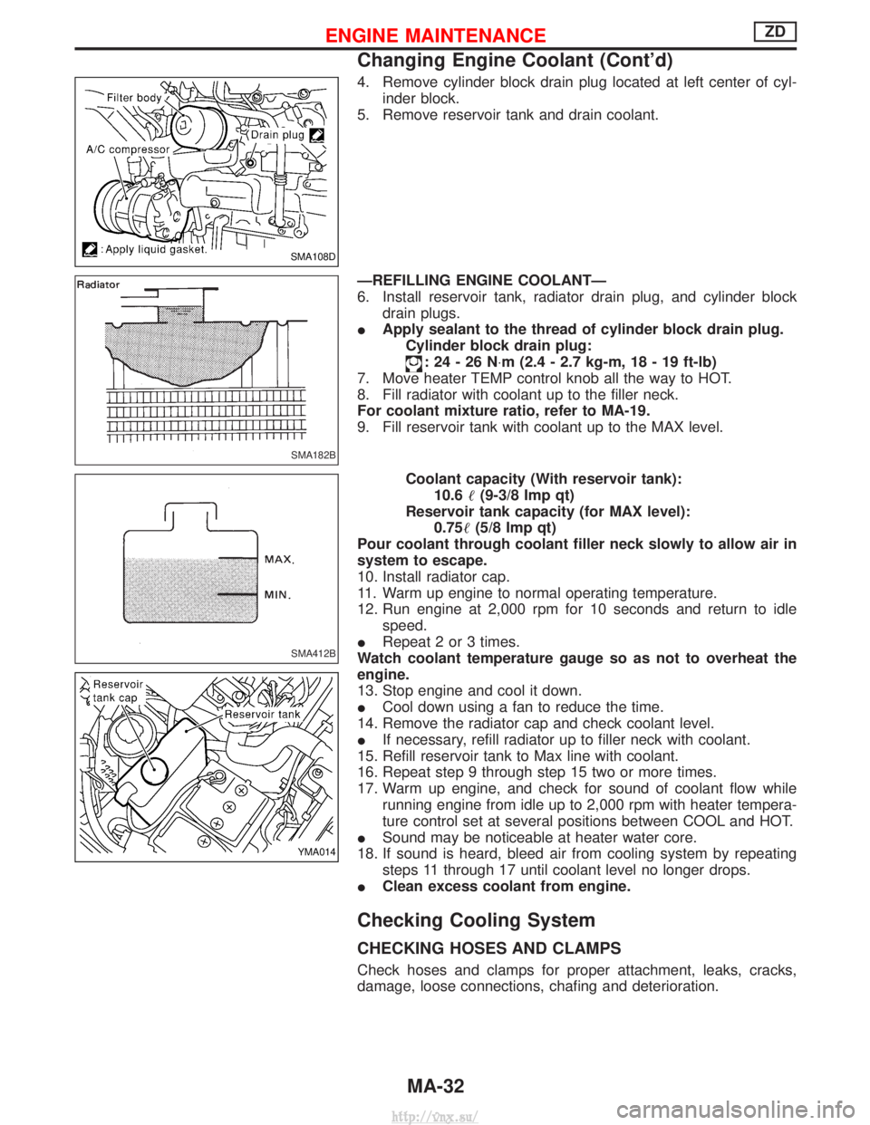
4. Remove cylinder block drain plug located at left center of cyl-inder block.
5. Remove reservoir tank and drain coolant.
ÐREFILLING ENGINE COOLANTÐ
6. Install reservoir tank, radiator drain plug, and cylinder block drain plugs.
I Apply sealant to the thread of cylinder block drain plug.
Cylinder block drain plug:
:24-26N ×m (2.4 - 2.7 kg-m, 18 - 19 ft-lb)
7. Move heater TEMP control knob all the way to HOT.
8. Fill radiator with coolant up to the filler neck.
For coolant mixture ratio, refer to MA-19.
9. Fill reservoir tank with coolant up to the MAX level.
Coolant capacity (With reservoir tank):10.6 (9-3/8 Imp qt)
Reservoir tank capacity (for MAX level): 0.75 (5/8 Imp qt)
Pour coolant through coolant filler neck slowly to allow air in
system to escape.
10. Install radiator cap.
11. Warm up engine to normal operating temperature.
12. Run engine at 2,000 rpm for 10 seconds and return to idle speed.
I Repeat 2 or 3 times.
Watch coolant temperature gauge so as not to overheat the
engine.
13. Stop engine and cool it down.
I Cool down using a fan to reduce the time.
14. Remove the radiator cap and check coolant level.
I If necessary, refill radiator up to filler neck with coolant.
15. Refill reservoir tank to Max line with coolant.
16. Repeat step 9 through step 15 two or more times.
17. Warm up engine, and check for sound of coolant flow while running engine from idle up to 2,000 rpm with heater tempera-
ture control set at several positions between COOL and HOT.
I Sound may be noticeable at heater water core.
18. If sound is heard, bleed air from cooling system by repeating steps 11 through 17 until coolant level no longer drops.
I Clean excess coolant from engine.
Checking Cooling System
CHECKING HOSES AND CLAMPS
Check hoses and clamps for proper attachment, leaks, cracks,
damage, loose connections, chafing and deterioration.
SMA108D
SMA182B
SMA412B
YMA014
ENGINE MAINTENANCEZD
Changing Engine Coolant (Cont'd)
MA-32
http://vnx.su/
Page 196 of 1833
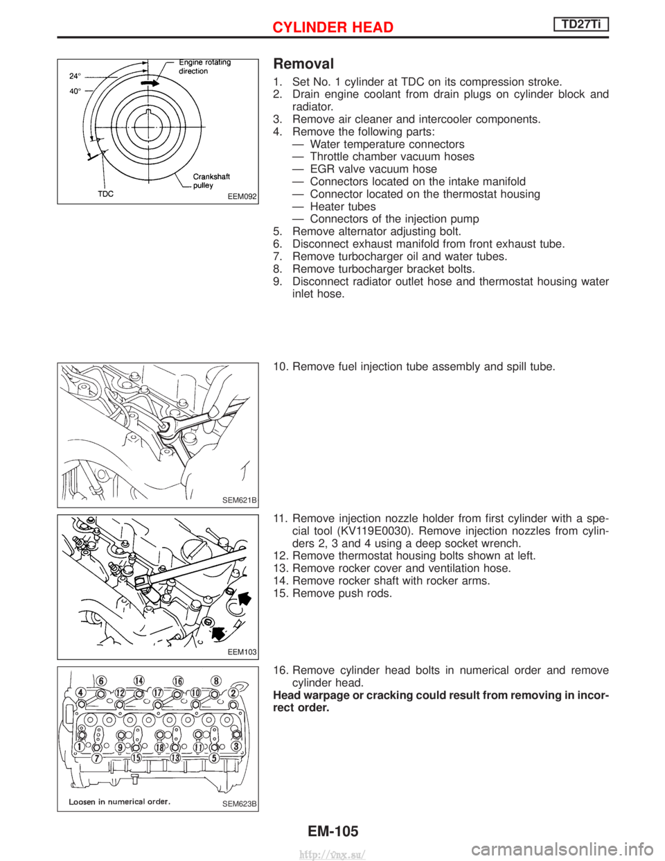
Removal
1. Set No. 1 cylinder at TDC on its compression stroke.
2. Drain engine coolant from drain plugs on cylinder block andradiator.
3. Remove air cleaner and intercooler components.
4. Remove the following parts: Ð Water temperature connectors
Ð Throttle chamber vacuum hoses
Ð EGR valve vacuum hose
Ð Connectors located on the intake manifold
Ð Connector located on the thermostat housing
Ð Heater tubes
Ð Connectors of the injection pump
5. Remove alternator adjusting bolt.
6. Disconnect exhaust manifold from front exhaust tube.
7. Remove turbocharger oil and water tubes.
8. Remove turbocharger bracket bolts.
9. Disconnect radiator outlet hose and thermostat housing water inlet hose.
10. Remove fuel injection tube assembly and spill tube.
11. Remove injection nozzle holder from first cylinder with a spe- cial tool (KV119E0030). Remove injection nozzles from cylin-
ders 2, 3 and 4 using a deep socket wrench.
12. Remove thermostat housing bolts shown at left.
13. Remove rocker cover and ventilation hose.
14. Remove rocker shaft with rocker arms.
15. Remove push rods.
16. Remove cylinder head bolts in numerical order and remove cylinder head.
Head warpage or cracking could result from removing in incor-
rect order.
EEM092
SEM621B
EEM103
SEM623B
CYLINDER HEADTD27Ti
EM-105
http://vnx.su/