2004 NISSAN TERRANO steering wheel
[x] Cancel search: steering wheelPage 1263 of 1833
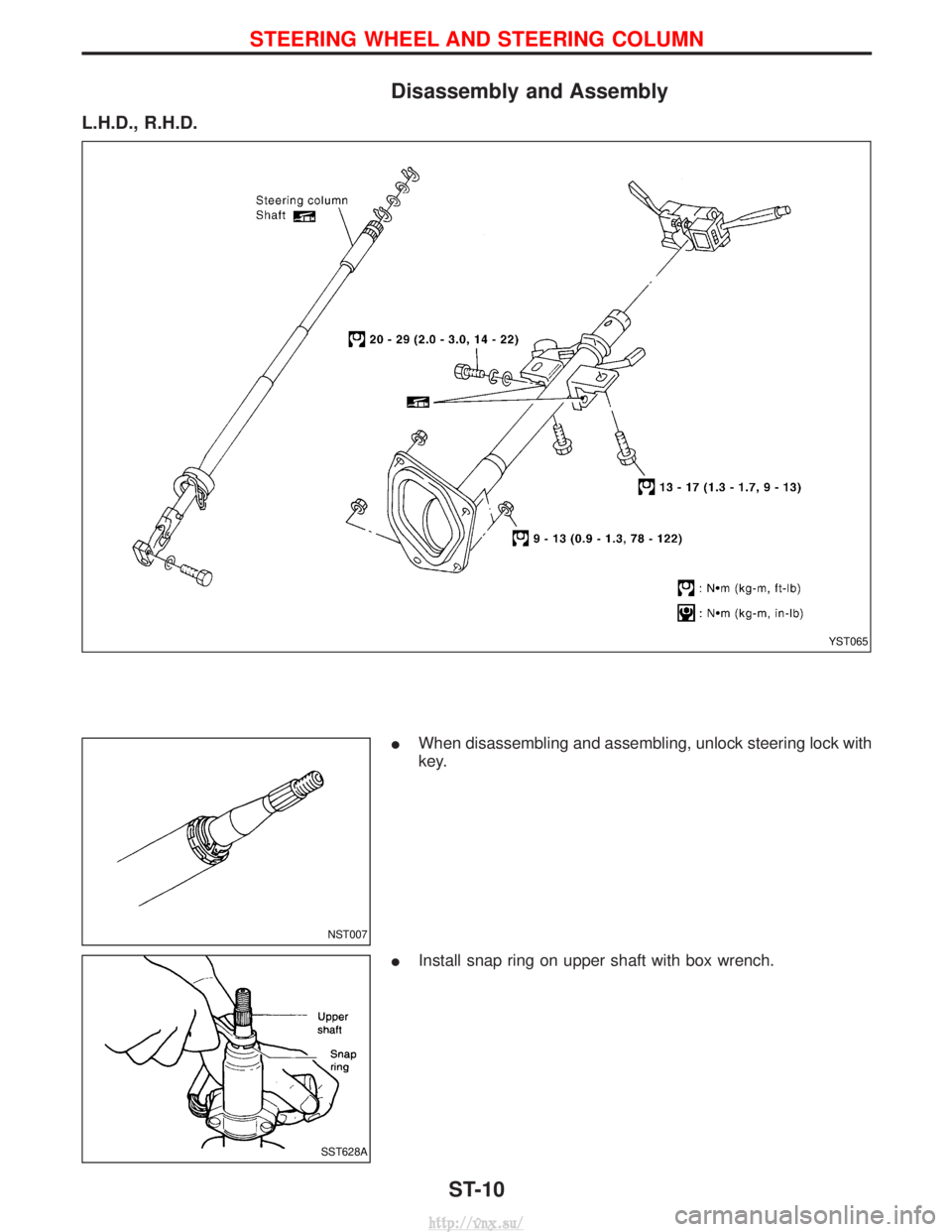
Disassembly and Assembly
L.H.D., R.H.D.
IWhen disassembling and assembling, unlock steering lock with
key.
I Install snap ring on upper shaft with box wrench.
YST065
NST007
SST628A
STEERING WHEEL AND STEERING COLUMN
ST-10
http://vnx.su/
Page 1264 of 1833
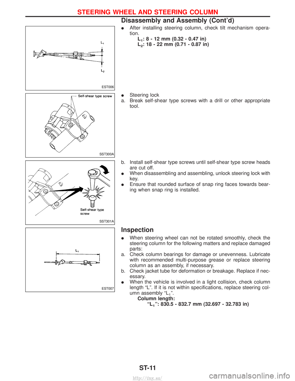
IAfter installing steering column, check tilt mechanism opera-
tion.
L
1:8-12mm (0.32 - 0.47 in)
L
2: 18 - 22 mm (0.71 - 0.87 in)
I Steering lock
a. Break self-shear type screws with a drill or other appropriate tool.
b. Install self-shear type screws until self-shear type screw heads are cut off.
I When disassembling and assembling, unlock steering lock with
key.
I Ensure that rounded surface of snap ring faces towards bear-
ing when snap ring is installed.
Inspection
IWhen steering wheel can not be rotated smoothly, check the
steering column for the following matters and replace damaged
parts:
a. Check column bearings for damage or unevenness. Lubricate with recommended multi-purpose grease or replace steering
column as an assembly, if necessary.
b. Check jacket tube for deformation or breakage. Replace if nec- essary.
I When the vehicle is involved in a light collision, check column
length ªLº. If it is not within specifications, replace steering col-
umn assembly ªL
1º.
Column length: ªL
1º: 830.5 - 832.7 mm (32.697 - 32.783 in)
EST006
SST300A
SST301A
EST007
STEERING WHEEL AND STEERING COLUMN
Disassembly and Assembly (Cont'd)
ST-11
http://vnx.su/
Page 1275 of 1833
General Specifications
ModelsAll
Steering gear type ZF 8054
Turns of steering
wheel
(Lock to lock) 3.86
Overall gear ratio 17.1 : 1
Steering column type Collapsible, adjustable height
Inspection and Adjustment
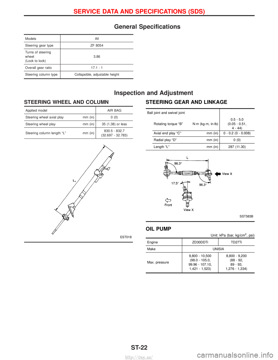
STEERING WHEEL AND COLUMN
Applied model AIR BAG
Steering wheel axial play mm (in) 0 (0)
Steering wheel play mm (in) 35 (1.38) or less
Steering column length ªLº mm (in) 830.5 - 832.7
(32.697 - 32.783)
EST018
STEERING GEAR AND LINKAGE
Ball joint and swivel joint
Rotating torque ªBº N×m (kg-m, in-lb) 0.5 - 5.0
(0.05 - 0.51, 4 - 44)
Axial end play ªCº mm (in) 0 - 0.2 (0 - 0.008)
Radial play ªDº mm (in) 0 (0)
Length ªLº mm (in) 287 (11.30)
SST583B
OIL PUMP
Unit: kPa (bar, kg/cm2, psi)
EngineZD30DDTiTD27Ti
Make UNISIA
Max. pressure 9,800 - 10,500
(98.0 - 105.0,
99.96 - 107.10, 1,421 - 1,523) 8,800 - 9,200
(88 - 92,89 - 93,
1,276 - 1,334)
SERVICE DATA AND SPECIFICATIONS (SDS)
ST-22
http://vnx.su/
Page 1283 of 1833
Precautions
SUPPLEMENTAL RESTRAINT SYSTEM (SRS) ªAIR BAGº AND ªSEAT BELT
PRE-TENSIONERº
The Supplemental Restraint System such as ªAIR BAGº and ªSEAT BELT PRE-TENSIONERº used along with
a seat belt, helps to reduce the risk or severity of injury to the driver and front passenger for certain types of
collision. The SRS composition which is available to NISSAN MODEL R20 is as follows (The composition
varies according to the destination and optional equipment.):
IFor a frontal collision
The Supplemental Restraint System consists of driver air bag module (located in the center of the steer-
ing wheel), front passenger air bag module (located on the instrument panel on passenger side), front seat
belt pre-tensioners, a diagnosis sensor unit, warning lamp, wiring harness and spiral cable.
I For a side collision
The Supplemental Restraint System consists of front side air bag module (located in the outer side of front
seat), side air bag (satellite) sensor, diagnosis sensor unit (one of components of air bags for a frontal
collision), wiring harness, warning lamp (one of components of air bags for a frontal collision).
WARNING:
I To avoid rendering the SRS inoperative, which could increase the risk of personal injury or death
in the event of a collision which would result in air bag inflation, all maintenance should be per-
formed by an authorized NISSAN dealer.
I Improper maintenance, including incorrect removal and installation of the SRS, can lead to per-
sonal injury caused by unintentional activation of the system.
I Do not use electrical test equipment on any circuit related to the SRS unless instructed to in this
Service Manual. Spiral cable and wiring harnesses covered with yellow insulation tape either just
before the harness connectors or for the complete harness are related to the SRS.
PRECAUTIONS FOR SRS ªAIR BAGº AND ªSEAT BELT PRE-TENSIONERº SERVICE
IDo not use electrical test equipment to check SRS circuits unless instructed to in this Service Manual.
I Before servicing the SRS, turn ignition switch ªOFFº, disconnect both battery cables and wait at least 3
minutes.
For approximately 3 minutes after the cables are removed, it is still possible for the air bag and seat belt
pre-tensioner to deploy. Therefore, do not work on any SRS connectors or wires until at least 3 minutes
have passed.
I Diagnosis sensor unit must always be installed with their arrow marks ª +º pointing towards the front of
the vehicle for proper operation. Also check diagnosis sensor unit for cracks, deformities or rust before
installation and replace as required.
I The spiral cable must be aligned with the neutral position since its rotations are limited. Do not attempt to
turn steering wheel or column after removal of steering gear.
I Handle air bag module carefully. Always place driver and front passenger air bag modules with the pad
side facing upward and place front side air bag module (built-in type) standing with stud bolt side setting
bottom.
I Conduct self-diagnosis to check entire SRS for proper function after replacing any components.
I After air bag inflates, the front instrument panel assembly should be replaced if damaged.
WIRING DIAGRAMS AND TROUBLE DIAGNOSIS
When you read wiring diagrams, refer to the following:
IGI-10, ªHOW TO READ WIRING DIAGRAMSº
I EL-8, ªPOWER SUPPLY ROUTINGº for power distribution circuit
When you perform trouble diagnosis, refer to the following:
I GI-25, ªHOW TO FOLLOW TEST GROUPS IN TROUBLE DIAGNOSISº
I GI-22, ªHOW TO PERFORM EFFICIENT DIAGNOSES FOR AN ELECTRICAL INCIDENTº
SUPPLEMENTAL RESTRAINT SYSTEM (SRS)
RS-8
http://vnx.su/
Page 1287 of 1833
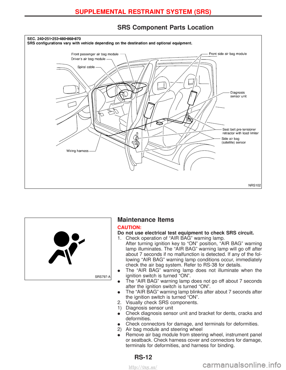
SRS Component Parts Location
Maintenance Items
CAUTION:
Do not use electrical test equipment to check SRS circuit.
1. Check operation of ªAIR BAGº warning lamp.After turning ignition key to ªONº position, ªAIR BAGº warning
lamp illuminates. The ªAIR BAGº warning lamp will go off after
about 7 seconds if no malfunction is detected. If any of the fol-
lowing ªAIR BAGº warning lamp conditions occur, immediately
check the air bag system. Refer to RS-38 for details.
I The ªAIR BAGº warning lamp does not illuminate when the
ignition switch is turned ªONº.
I The ªAIR BAGº warning lamp does not go off about 7 seconds
after the ignition switch is turned ªONº.
I The ªAIR BAGº warning lamp blinks after about 7 seconds after
the ignition switch is turned ªONº.
2. Visually check SRS components.
1) Diagnosis sensor unit
I Check diagnosis sensor unit and bracket for dents, cracks and
deformities.
I Check connectors for damage, and terminals for deformities.
2) Air bag module and steering wheel
I Remove air bag module from steering wheel, instrument panel
or seatback. Check harness cover and connectors for damage,
terminals for deformities, and harness for binding.
NRS102
SRS797-A
SUPPLEMENTAL RESTRAINT SYSTEM (SRS)
RS-12
http://vnx.su/
Page 1288 of 1833
IInstall driver air bag module to steering wheel to check fit or
alignment with the wheel.
I Check steering wheel for excessive free play.
I Install front passenger air bag module to instrument panel to
check fit or alignment with the instrument panel.
I Install front side air bag module to seatback to check fit and
alignment with the seat.
3) Spiral cable
I Check spiral cable for dents, cracks, or deformities.
I Check connectors and protective tape for damage.
I Check steering wheel for noise, binding or heavy operation.
4) Main harness, body harness, side air bag module sub-harness
I Check connectors for poor connections, damage, and terminals
for deformities.
I Check harnesses for binding, chafing or cut.
5) Front seat belt pre-tensioner
I Check harness cover and connectors for damage, terminals for
deformities, and harness for binding.
I Check belts for damage and anchors for loose mounting.
I Check retractor for smooth operation.
I Perform self-diagnosis for seat belt pre-tensioner using ªAIR
BAGº warning lamp or CONSULT-II.
Refer to ªSRS Operation Checkº for details. (RS-38)
6) Side air bag (satellite) sensor
I Check side air bag (satellite) sensor (including bracket portion)
for dents, cracks or deformities.
I Check connectors for damage, and terminals for deformities.
CAUTION:
Replace previously used special bolts and ground bolt with
new ones.
Diagnosis Sensor Unit
REMOVAL AND INSTALLATION
CAUTION:
I Before servicing SRS, turn the ignition switch off, discon-
nect both battery cables and wait at least 3 minutes.
I The special bolts are coated with bonding agent while the
other bolt is for ground. Do not use old bolts after removal;
replace with new ones.
I Check diagnosis sensor unit for proper installation.
I Check diagnosis sensor unit to ensure it is free of
deformities, dents, cracks or rust. If they show any visible
signs of damage, replace them with new ones.
I Check diagnosis sensor unit brackets to ensure they are
free of deformities or rust.
I Replace diagnosis sensor unit if it has been dropped or
sustained an impact.
I After replacement of diagnosis sensor unit, perform self-
diagnosis for SRS. Refer to ªSRS Operation Checkº for
details. (RS-38)
1. Disconnect driver, front passenger and front side air bag mod- ule connectors. Also, disconnect front seat belt pre-tensioner
connector.
2. Remove console box. Refer to BT-22, ªINSTRUMENT PANEL ASSEMBLYº.
3. Disconnect diagnosis sensor unit connector.
4. Remove ground bolt and also remove special bolts using the TAMPER RESISTANT TORX (Size T50), from diagnosis sen-
sor unit.
Then remove the diagnosis sensor unit.
SUPPLEMENTAL RESTRAINT SYSTEM (SRS)
Maintenance Items (Cont'd)
RS-13
http://vnx.su/
Page 1293 of 1833
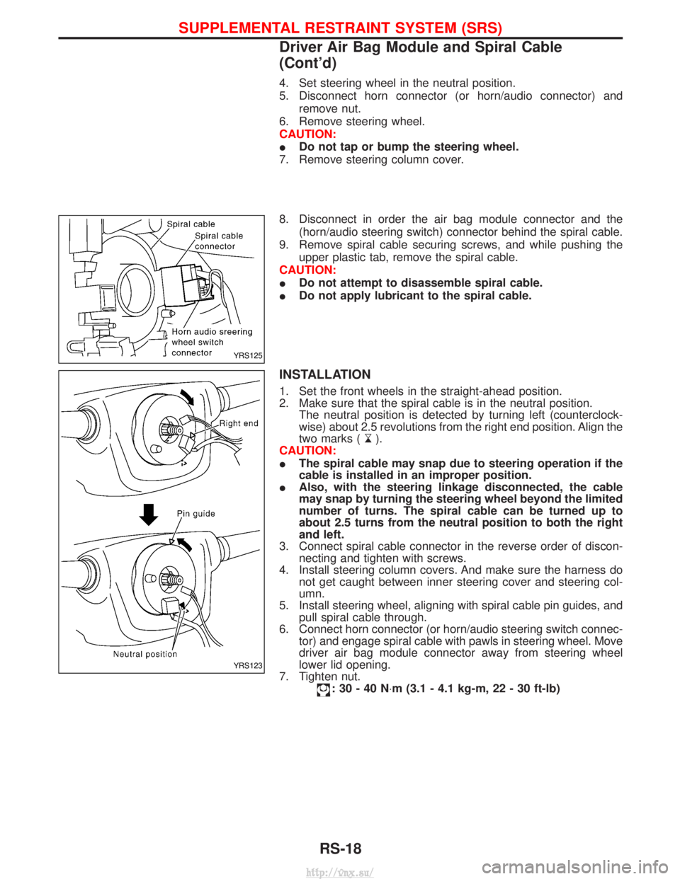
4. Set steering wheel in the neutral position.
5. Disconnect horn connector (or horn/audio connector) andremove nut.
6. Remove steering wheel.
CAUTION:
I Do not tap or bump the steering wheel.
7. Remove steering column cover.
8. Disconnect in order the air bag module connector and the (horn/audio steering switch) connector behind the spiral cable.
9. Remove spiral cable securing screws, and while pushing the upper plastic tab, remove the spiral cable.
CAUTION:
I Do not attempt to disassemble spiral cable.
I Do not apply lubricant to the spiral cable.
INSTALLATION
1. Set the front wheels in the straight-ahead position.
2. Make sure that the spiral cable is in the neutral position.
The neutral position is detected by turning left (counterclock-
wise) about 2.5 revolutions from the right end position. Align the
two marks (
).
CAUTION:
I The spiral cable may snap due to steering operation if the
cable is installed in an improper position.
I Also, with the steering linkage disconnected, the cable
may snap by turning the steering wheel beyond the limited
number of turns. The spiral cable can be turned up to
about 2.5 turns from the neutral position to both the right
and left.
3. Connect spiral cable connector in the reverse order of discon- necting and tighten with screws.
4. Install steering column covers. And make sure the harness do not get caught between inner steering cover and steering col-
umn.
5. Install steering wheel, aligning with spiral cable pin guides, and pull spiral cable through.
6. Connect horn connector (or horn/audio steering switch connec- tor) and engage spiral cable with pawls in steering wheel. Move
driver air bag module connector away from steering wheel
lower lid opening.
7. Tighten nut.
:30-40N ×m (3.1 - 4.1 kg-m, 22 - 30 ft-lb)
YRS125
YRS123
SUPPLEMENTAL RESTRAINT SYSTEM (SRS)
Driver Air Bag Module and Spiral Cable
(Cont'd)
RS-18
http://vnx.su/
Page 1294 of 1833
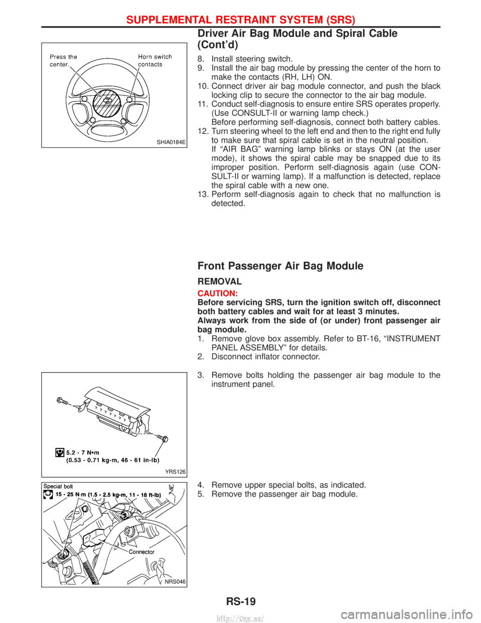
8. Install steering switch.
9. Install the air bag module by pressing the center of the horn tomake the contacts (RH, LH) ON.
10. Connect driver air bag module connector, and push the black locking clip to secure the connector to the air bag module.
11. Conduct self-diagnosis to ensure entire SRS operates properly. (Use CONSULT-II or warning lamp check.)
Before performing self-diagnosis, connect both battery cables.
12. Turn steering wheel to the left end and then to the right end fully to make sure that spiral cable is set in the neutral position.
If ªAIR BAGº warning lamp blinks or stays ON (at the user
mode), it shows the spiral cable may be snapped due to its
improper position. Perform self-diagnosis again (use CON-
SULT-II or warning lamp). If a malfunction is detected, replace
the spiral cable with a new one.
13. Perform self-diagnosis again to check that no malfunction is detected.
Front Passenger Air Bag Module
REMOVAL
CAUTION:
Before servicing SRS, turn the ignition switch off, disconnect
both battery cables and wait for at least 3 minutes.
Always work from the side of (or under) front passenger air
bag module.
1. Remove glove box assembly. Refer to BT-16, ªINSTRUMENTPANEL ASSEMBLYº for details.
2. Disconnect inflator connector.
3. Remove bolts holding the passenger air bag module to the instrument panel.
4. Remove upper special bolts, as indicated.
5. Remove the passenger air bag module.
SHIA0184E
YRS126
NRS046
SUPPLEMENTAL RESTRAINT SYSTEM (SRS)
Driver Air Bag Module and Spiral Cable
(Cont'd)
RS-19
http://vnx.su/