2004 NISSAN TERRANO oil type
[x] Cancel search: oil typePage 1275 of 1833
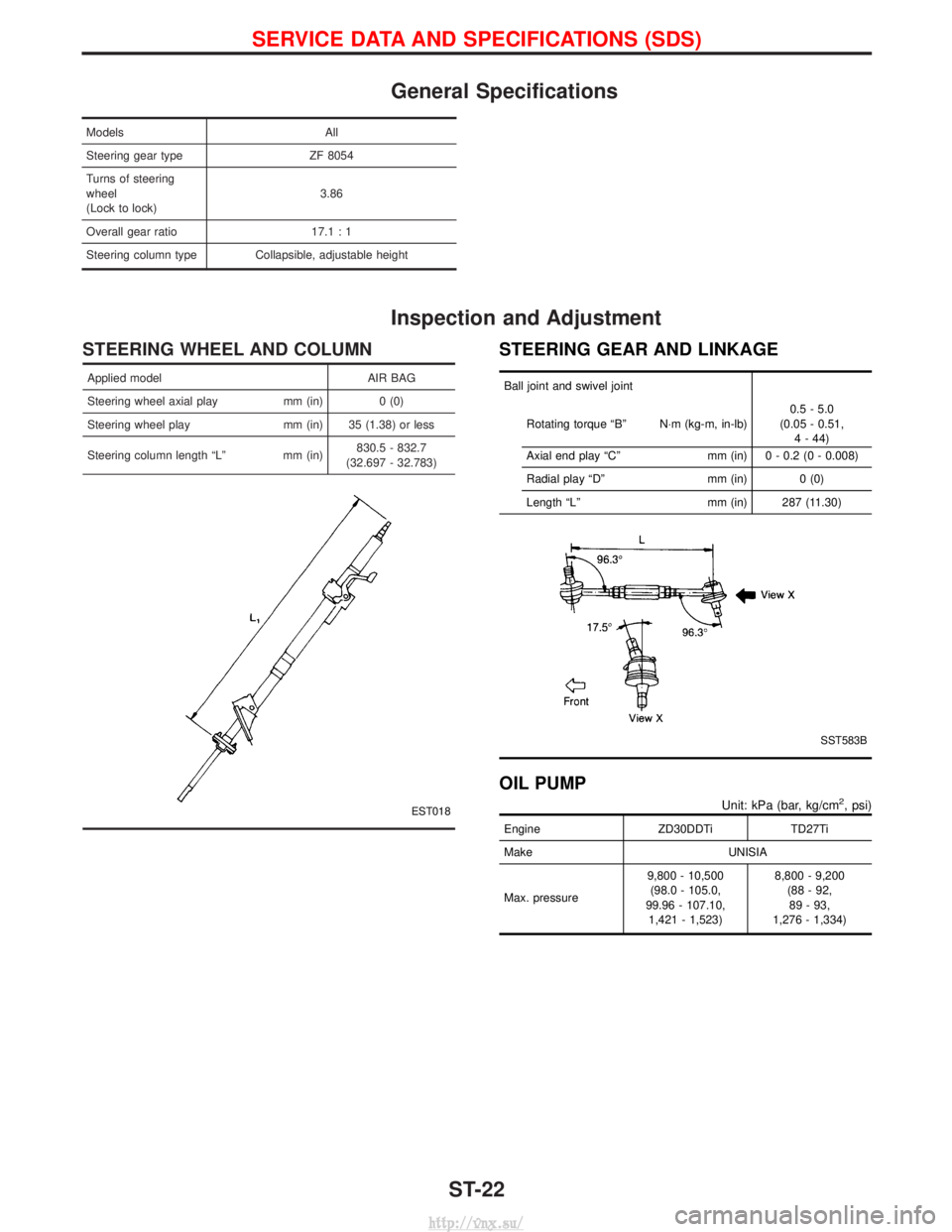
General Specifications
ModelsAll
Steering gear type ZF 8054
Turns of steering
wheel
(Lock to lock) 3.86
Overall gear ratio 17.1 : 1
Steering column type Collapsible, adjustable height
Inspection and Adjustment
STEERING WHEEL AND COLUMN
Applied model AIR BAG
Steering wheel axial play mm (in) 0 (0)
Steering wheel play mm (in) 35 (1.38) or less
Steering column length ªLº mm (in) 830.5 - 832.7
(32.697 - 32.783)
EST018
STEERING GEAR AND LINKAGE
Ball joint and swivel joint
Rotating torque ªBº N×m (kg-m, in-lb) 0.5 - 5.0
(0.05 - 0.51, 4 - 44)
Axial end play ªCº mm (in) 0 - 0.2 (0 - 0.008)
Radial play ªDº mm (in) 0 (0)
Length ªLº mm (in) 287 (11.30)
SST583B
OIL PUMP
Unit: kPa (bar, kg/cm2, psi)
EngineZD30DDTiTD27Ti
Make UNISIA
Max. pressure 9,800 - 10,500
(98.0 - 105.0,
99.96 - 107.10, 1,421 - 1,523) 8,800 - 9,200
(88 - 92,89 - 93,
1,276 - 1,334)
SERVICE DATA AND SPECIFICATIONS (SDS)
ST-22
http://vnx.su/
Page 1277 of 1833
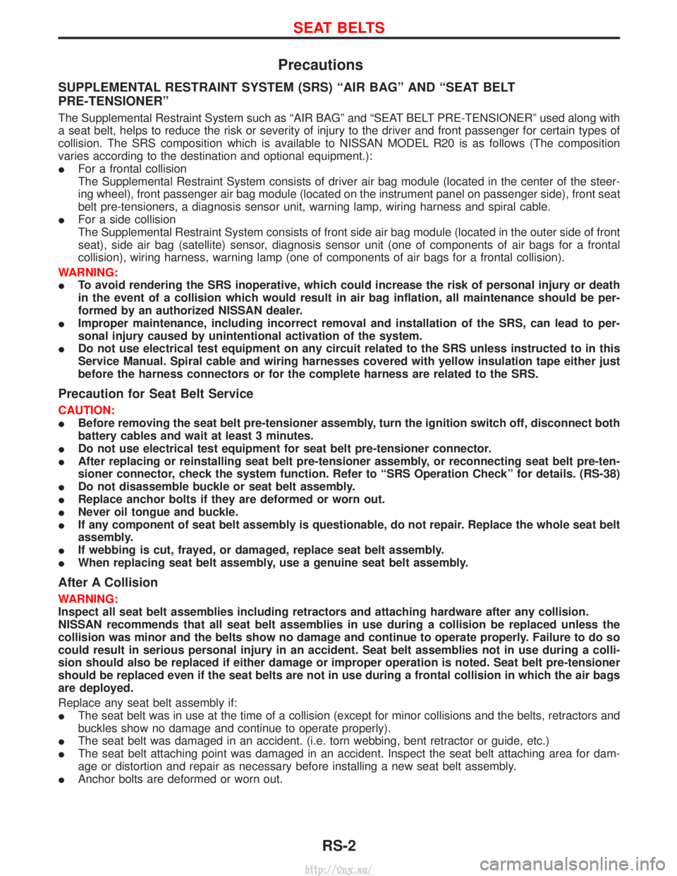
Precautions
SUPPLEMENTAL RESTRAINT SYSTEM (SRS) ªAIR BAGº AND ªSEAT BELT
PRE-TENSIONERº
The Supplemental Restraint System such as ªAIR BAGº and ªSEAT BELT PRE-TENSIONERº used along with
a seat belt, helps to reduce the risk or severity of injury to the driver and front passenger for certain types of
collision. The SRS composition which is available to NISSAN MODEL R20 is as follows (The composition
varies according to the destination and optional equipment.):
IFor a frontal collision
The Supplemental Restraint System consists of driver air bag module (located in the center of the steer-
ing wheel), front passenger air bag module (located on the instrument panel on passenger side), front seat
belt pre-tensioners, a diagnosis sensor unit, warning lamp, wiring harness and spiral cable.
I For a side collision
The Supplemental Restraint System consists of front side air bag module (located in the outer side of front
seat), side air bag (satellite) sensor, diagnosis sensor unit (one of components of air bags for a frontal
collision), wiring harness, warning lamp (one of components of air bags for a frontal collision).
WARNING:
I To avoid rendering the SRS inoperative, which could increase the risk of personal injury or death
in the event of a collision which would result in air bag inflation, all maintenance should be per-
formed by an authorized NISSAN dealer.
I Improper maintenance, including incorrect removal and installation of the SRS, can lead to per-
sonal injury caused by unintentional activation of the system.
I Do not use electrical test equipment on any circuit related to the SRS unless instructed to in this
Service Manual. Spiral cable and wiring harnesses covered with yellow insulation tape either just
before the harness connectors or for the complete harness are related to the SRS.
Precaution for Seat Belt Service
CAUTION:
IBefore removing the seat belt pre-tensioner assembly, turn the ignition switch off, disconnect both
battery cables and wait at least 3 minutes.
I Do not use electrical test equipment for seat belt pre-tensioner connector.
I After replacing or reinstalling seat belt pre-tensioner assembly, or reconnecting seat belt pre-ten-
sioner connector, check the system function. Refer to ªSRS Operation Checkº for details. (RS-38)
I Do not disassemble buckle or seat belt assembly.
I Replace anchor bolts if they are deformed or worn out.
I Never oil tongue and buckle.
I If any component of seat belt assembly is questionable, do not repair. Replace the whole seat belt
assembly.
I If webbing is cut, frayed, or damaged, replace seat belt assembly.
I When replacing seat belt assembly, use a genuine seat belt assembly.
After A Collision
WARNING:
Inspect all seat belt assemblies including retractors and attaching hardware after any collision.
NISSAN recommends that all seat belt assemblies in use during a collision be replaced unless the
collision was minor and the belts show no damage and continue to operate properly. Failure to do so
could result in serious personal injury in an accident. Seat belt assemblies not in use during a colli-
sion should also be replaced if either damage or improper operation is noted. Seat belt pre-tensioner
should be replaced even if the seat belts are not in use during a frontal collision in which the air bags
are deployed.
Replace any seat belt assembly if:
IThe seat belt was in use at the time of a collision (except for minor collisions and the belts, retractors and
buckles show no damage and continue to operate properly).
I The seat belt was damaged in an accident. (i.e. torn webbing, bent retractor or guide, etc.)
I The seat belt attaching point was damaged in an accident. Inspect the seat belt attaching area for dam-
age or distortion and repair as necessary before installing a new seat belt assembly.
I Anchor bolts are deformed or worn out.
SEAT BELTS
RS-2
http://vnx.su/
Page 1339 of 1833
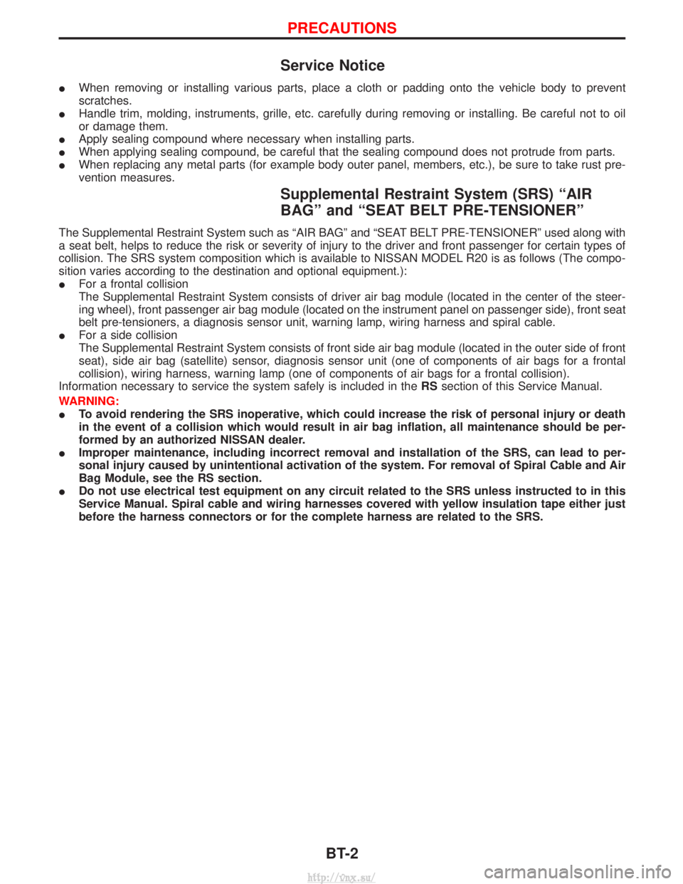
Service Notice
IWhen removing or installing various parts, place a cloth or padding onto the vehicle body to prevent
scratches.
I Handle trim, molding, instruments, grille, etc. carefully during removing or installing. Be careful not to oil
or damage them.
I Apply sealing compound where necessary when installing parts.
I When applying sealing compound, be careful that the sealing compound does not protrude from parts.
I When replacing any metal parts (for example body outer panel, members, etc.), be sure to take rust pre-
vention measures.
Supplemental Restraint System (SRS) ªAIR
BAGº and ªSEAT BELT PRE-TENSIONERº
The Supplemental Restraint System such as ªAIR BAGº and ªSEAT BELT PRE-TENSIONERº used along with
a seat belt, helps to reduce the risk or severity of injury to the driver and front passenger for certain types of
collision. The SRS system composition which is available to NISSAN MODEL R20 is as follows (The compo-
sition varies according to the destination and optional equipment.):
IFor a frontal collision
The Supplemental Restraint System consists of driver air bag module (located in the center of the steer-
ing wheel), front passenger air bag module (located on the instrument panel on passenger side), front seat
belt pre-tensioners, a diagnosis sensor unit, warning lamp, wiring harness and spiral cable.
I For a side collision
The Supplemental Restraint System consists of front side air bag module (located in the outer side of front
seat), side air bag (satellite) sensor, diagnosis sensor unit (one of components of air bags for a frontal
collision), wiring harness, warning lamp (one of components of air bags for a frontal collision).
Information necessary to service the system safely is included in the RSsection of this Service Manual.
WARNING:
I To avoid rendering the SRS inoperative, which could increase the risk of personal injury or death
in the event of a collision which would result in air bag inflation, all maintenance should be per-
formed by an authorized NISSAN dealer.
I Improper maintenance, including incorrect removal and installation of the SRS, can lead to per-
sonal injury caused by unintentional activation of the system. For removal of Spiral Cable and Air
Bag Module, see the RS section.
I Do not use electrical test equipment on any circuit related to the SRS unless instructed to in this
Service Manual. Spiral cable and wiring harnesses covered with yellow insulation tape either just
before the harness connectors or for the complete harness are related to the SRS.
PRECAUTIONS
BT-2
http://vnx.su/
Page 1401 of 1833
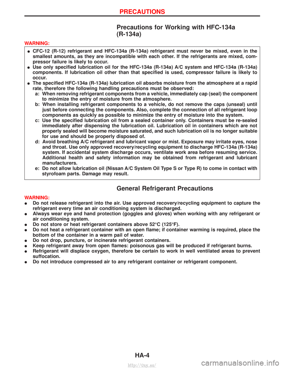
Precautions for Working with HFC-134a
(R-134a)
WARNING:I CFC-12 (R-12) refrigerant and HFC-134a (R-134a) refrigerant must never be mixed, even in the
smallest amounts, as they are incompatible with each other. If the refrigerants are mixed, com-
pressor failure is likely to occur.
I Use only specified lubrication oil for the HFC-134a (R-134a) A/C system and HFC-134a (R-134a)
components. If lubrication oil other than that specified is used, compressor failure is likely to
occur.
I The specified HFC-134a (R-134a) lubrication oil absorbs moisture from the atmosphere at a rapid
rate, therefore the following handling precautions must be observed:
a: When removing refrigerant components from a vehicle, immediately cap (seal) the component to minimize the entry of moisture from the atmosphere.
b: When installing refrigerant components to a vehicle, do not remove the caps (unseal) until just before connecting the components. Also, complete the connection of all refrigerant loop
components as quickly as possible to minimize the entry of moisture into the system.
c: Use the specified lubrication oil from a sealed container only. Containers must be re-sealed immediately after dispensing the lubrication oil. Lubrication oil in containers which are not
properly sealed will become moisture saturated, and such lubrication oil is no longer suitable
for use and should be properly disposed of.
d: Avoid breathing A/C refrigerant and lubricant vapor or mist. Exposure may irritate eyes, nose and throat. Use only approved recovery/recycling equipment to discharge HFC-134a (R-134a)
system. If accidental system discharge occurs, ventilate work area before resuming service.
Additional health and safety information may be obtained from refrigerant and lubricant
manufacturers.
e: Do not allow lubrication oil (Nissan A/C System Oil Type S or Type R) to come in contact with styrofoam parts. Damage may result.
General Refrigerant Precautions
WARNING:
I Do not release refrigerant into the air. Use approved recovery/recycling equipment to capture the
refrigerant every time an air conditioning system is discharged.
I Always wear eye and hand protection (goggles and gloves) when working with any refrigerant or
air conditioning system.
I Do not store or heat refrigerant containers above 52ÉC (125ÉF).
I Do not heat a refrigerant container with an open flame; if container warming is required, place the
bottom of the container in a warm pail of water.
I Do not drop, puncture, or incinerate refrigerant containers.
I Keep refrigerant away from open flames: poisonous gas will be produced if refrigerant burns.
I Refrigerant will displace oxygen, therefore be certain to work in well ventilated areas to prevent
suffocation.
I Do not introduce compressed air to any refrigerant container or refrigerant component.
PRECAUTIONS
HA-4
http://vnx.su/
Page 1402 of 1833
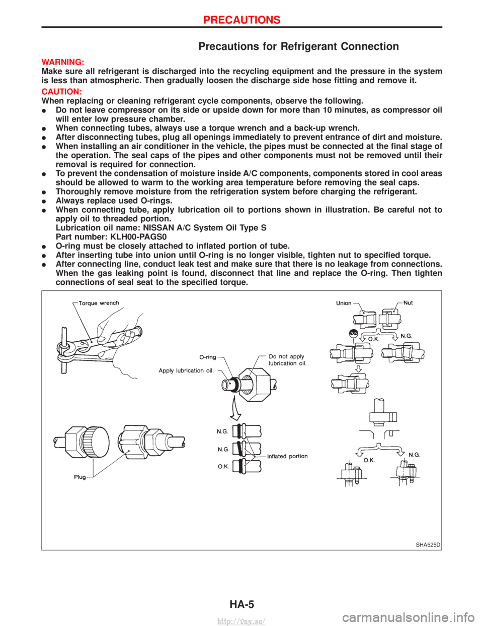
Precautions for Refrigerant Connection
WARNING:
Make sure all refrigerant is discharged into the recycling equipment and the pressure in the system
is less than atmospheric. Then gradually loosen the discharge side hose fitting and remove it.
CAUTION:
When replacing or cleaning refrigerant cycle components, observe the following.
IDo not leave compressor on its side or upside down for more than 10 minutes, as compressor oil
will enter low pressure chamber.
I When connecting tubes, always use a torque wrench and a back-up wrench.
I After disconnecting tubes, plug all openings immediately to prevent entrance of dirt and moisture.
I When installing an air conditioner in the vehicle, the pipes must be connected at the final stage of
the operation. The seal caps of the pipes and other components must not be removed until their
removal is required for connection.
I To prevent the condensation of moisture inside A/C components, components stored in cool areas
should be allowed to warm to the working area temperature before removing the seal caps.
I Thoroughly remove moisture from the refrigeration system before charging the refrigerant.
I Always replace used O-rings.
I When connecting tube, apply lubrication oil to portions shown in illustration. Be careful not to
apply oil to threaded portion.
Lubrication oil name: NISSAN A/C System Oil Type S
Part number: KLH00-PAGS0
I O-ring must be closely attached to inflated portion of tube.
I After inserting tube into union until O-ring is no longer visible, tighten nut to specified torque.
I After connecting line, conduct leak test and make sure that there is no leakage from connections.
When the gas leaking point is found, disconnect that line and replace the O-ring. Then tighten
connections of seal seat to the specified torque.
SHA525D
PRECAUTIONS
HA-5
http://vnx.su/
Page 1409 of 1833
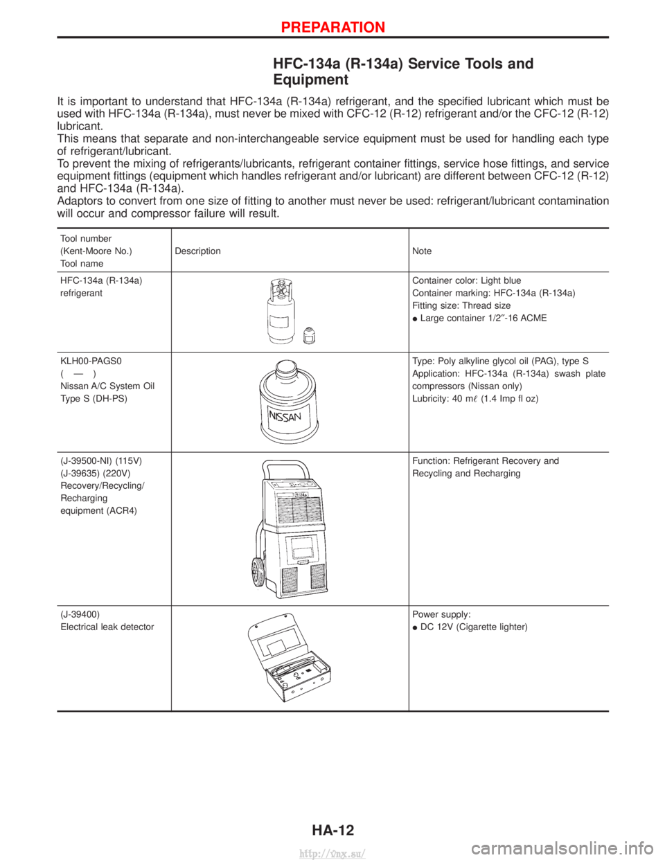
HFC-134a (R-134a) Service Tools and
Equipment
It is important to understand that HFC-134a (R-134a) refrigerant, and the specified lubricant which must be
used with HFC-134a (R-134a), must never be mixed with CFC-12 (R-12) refrigerant and/or the CFC-12 (R-12)
lubricant.
This means that separate and non-interchangeable service equipment must be used for handling each type
of refrigerant/lubricant.
To prevent the mixing of refrigerants/lubricants, refrigerant container fittings, service hose fittings, and service
equipment fittings (equipment which handles refrigerant and/or lubricant) are different between CFC-12 (R-12)
and HFC-134a (R-134a).
Adaptors to convert from one size of fitting to another must never be used: refrigerant/lubricant contamination
will occur and compressor failure will result.
Tool number
(Kent-Moore No.)
Tool nameDescription Note
HFC-134a (R-134a)
refrigerant
Container color: Light blue
Container marking: HFC-134a (R-134a)
Fitting size: Thread size
I Large container 1/2² -16 ACME
KLH00-PAGS0
(Ð)
Nissan A/C System Oil
Type S (DH-PS)
Type: Poly alkyline glycol oil (PAG), type S
Application: HFC-134a (R-134a) swash plate
compressors (Nissan only)
Lubricity: 40 m (1.4 Imp fl oz)
(J-39500-NI) (115V)
(J-39635) (220V)
Recovery/Recycling/
Recharging
equipment (ACR4)
Function: Refrigerant Recovery and
Recycling and Recharging
(J-39400)
Electrical leak detector
Power supply:
I DC 12V (Cigarette lighter)
PREPARATION
HA-12
http://vnx.su/
Page 1420 of 1833
Lubrication Oil
Name: Nissan A/C System Oil Type S
Part number: KLH00-PAGS0
Maintenance of Oil Quantity in Compressor
The oil used to lubricate the compressor circulates through the
system with the refrigerant. Whenever any component of the sys-
tem is replaced or a large amount of gas leakage occurs, add oil
to the compressor to maintain the specified amount.
If oil quantity is not maintained properly, the following malfunctions
may result:
ILack of oil: May lead to a seized compressor
I Excessive oil: Inadequate cooling (thermal exchange impeded)
Checking and Adjusting
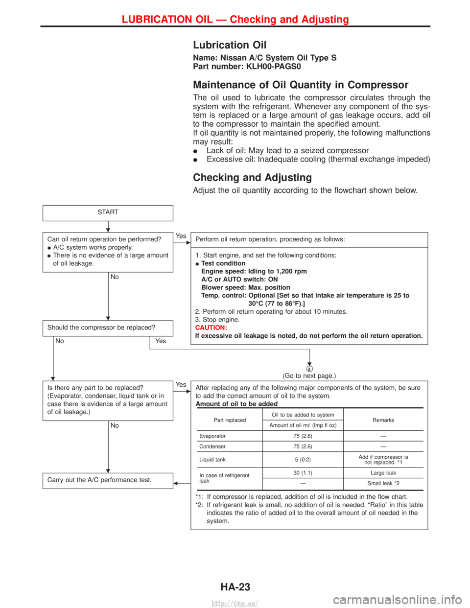
Adjust the oil quantity according to the flowchart shown below.
START
Can oil return operation be performed?
IA/C system works properly.
I There is no evidence of a large amount
of oil leakage.
No
EYe s
Perform oil return operation, proceeding as follows:
------------------------------------------------------------------------------------------------------------------------------------------------------------------------------------------------------------------------------------------------------------------------------------------------------------------------------------------------------------------------------------------------------------------------------------------------------------------------------------------------------------------------------------------------------------- 1. Start engine, and set the following conditions:
I Test condition
Engine speed: Idling to 1,200 rpm
A/C or AUTO switch: ON
Blower speed: Max. position
Temp. control: Optional [Set so that intake air temperature is 25 to
30ÉC (77 to 86ÉF).]
2. Perform oil return operating for about 10 minutes.
3. Stop engine.
CAUTION:
If excessive oil leakage is noted, do not perform the oil return operation.
Should the compressor be replaced?
No Yes
qA(Go to next page.)
Is there any part to be replaced?
(Evaporator, condenser, liquid tank or in
case there is evidence of a large amount
of oil leakage.)
No
EYe s After replacing any of the following major components of the system, be sure
to add the correct amount of oil to the system.
Amount of oil to be added
*1: If compressor is replaced, addition of oil is included in the flow chart.
*2: If refrigerant leak is small, no addition of oil is needed. ªRatioº in this table indicates the ratio of added oil to the overall amount of oil needed in the
system.
Carry out the A/C performance test.F
Part replaced Oil to be added to system
Remarks
Amount of oil m (Imp fl oz)
Evaporator 75 (2.6)Ð
Condenser 75 (2.6)Ð
Liquid tank 5 (0.2)Add if compressor is
not replaced. *1
In case of refrigerant
leak 30 (1.1)
Large leak
Ð Small leak *2
H
H
H
H
H
LUBRICATION OIL Ð Checking and Adjusting
HA-23
http://vnx.su/
Page 1462 of 1833
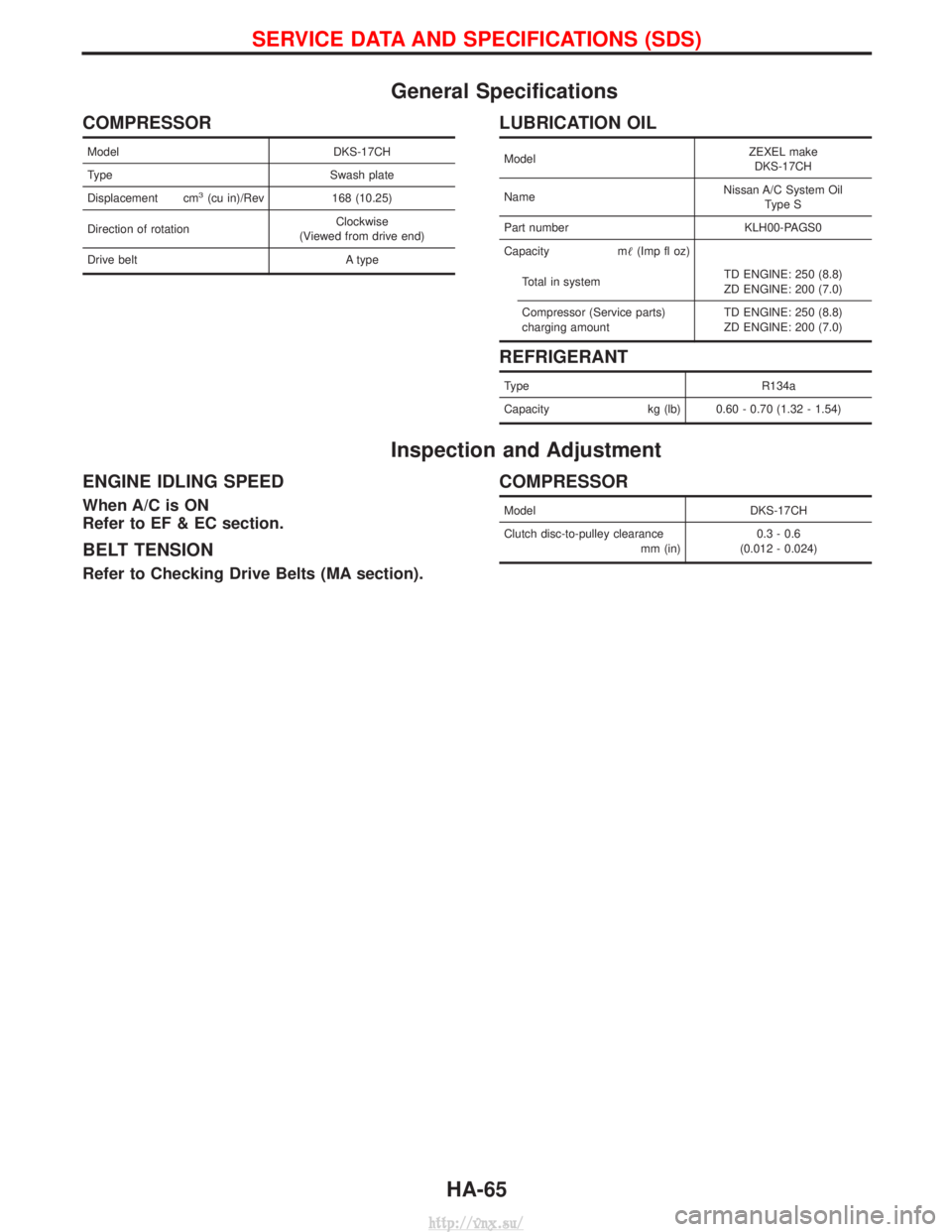
General Specifications
COMPRESSOR
ModelDKS-17CH
Type Swash plate
Displacement cm
3(cu in)/Rev 168 (10.25)
Direction of rotation Clockwise
(Viewed from drive end)
Drive belt A type
LUBRICATION OIL
ModelZEXEL make
DKS-17CH
Name Nissan A/C System Oil
Type S
Part number KLH00-PAGS0
Capacity m (Imp fl oz)
Total in system TD ENGINE: 250 (8.8)
ZD ENGINE: 200 (7.0)
Compressor (Service parts)
charging amount TD ENGINE: 250 (8.8)
ZD ENGINE: 200 (7.0)
REFRIGERANT
Type
R134a
Capacity kg (lb) 0.60 - 0.70 (1.32 - 1.54)
Inspection and Adjustment
ENGINE IDLING SPEED
When A/C is ON
Refer to EF & EC section.
BELT TENSION
Refer to Checking Drive Belts (MA section).
COMPRESSOR
Model DKS-17CH
Clutch disc-to-pulley clearance mm (in)0.3 - 0.6
(0.012 - 0.024)
SERVICE DATA AND SPECIFICATIONS (SDS)
HA-65
http://vnx.su/