2004 NISSAN TERRANO manual transmission
[x] Cancel search: manual transmissionPage 51 of 1833

Chassis and Body Maintenance
Abbreviations: R = Replace I = Inspect. Correct or replace if necessary L = Lubricate T = Tighten
MAINTENANCE OPERATIONMAINTENANCE INTERVAL
Refer-
ence
page
Perform on a kilometer basis only. km x 1,000 10 20 30 40 50 60 70 80 90 100 110 120
(miles x 1,000) (6) (12) (18) (24) (30) (36) (42) (48) (54) (60) (66) (72)
Underhood and under vehicle
Headlamp aiming
IIIIEL-41
Wheel alignment (it necessary, rotate & balance wheels) IIIIMA-43
Brake pads, discs & other components* IIIIMA-40
Brake linings, drums & other components* IIIIMA-41
Foot brake, parking brake & clutch (for free play, stroke &
operation) IIII
MA-42
Brake booster vacuum hoses, connections, check valve I I MA-40
Brake & clutch, systems and fluid (for level and leaks) IIIIMA-36/
MA-40
Brake fluid* R R MA-43
Power steering fluid and lines (for level and leaks) IIIIMA-44
Air bag system See NOTE (1) RS-17
Ventilation air filter* RRRRMA-44
Transfer and standard differential gear oil* IRIRMA-37/
MA-38
Manual transmission oil I I R I MA-36
LSD gear oil* IRIRMA-38
Steering gar & linkage, axle & suspension parts, propeller shaft
and exhaust system* IIIIMA-43/
FA-4/
RA-4/
MA-38/ MA-36
Greasing points of steering gear linkage,
propeller shaft and suspension* See NOTE (2)
LLLL MA-44/
MA-38
Drive shafts* IIIIFA-13
Front wheel bearing grease* IRIRMA-39
Free running hub grease* IIIIMA-40
Body mounting bolts and nuts TTTTBT-48
Body corrosion See NOTE (3) MA-47
NOTE: (1) Inspect after 10 years, then every 2 years.
(2) The propeller shaft should be re-greased daily if it is immersed in water.
(3) Inspect once per year.
* Maintenance items with ª*º should be performed more frequently according to ªMaintenance under severe drivingconditionsº.
PERIODIC MAINTENANCE
Maintenance Schedule for Diesel Engine
Models (annual mileage > 30,000 km/year)
(Cont'd)
MA-10
http://vnx.su/
Page 58 of 1833
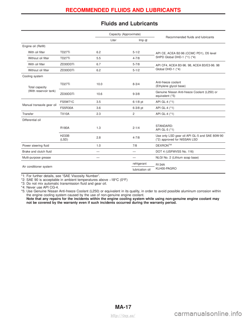
Fluids and Lubricants
Capacity (Approximate)Recommended fluids and lubricants
Liter Imp qt
Engine oil (Refill) With oil filter TD27Ti 6.2 5-1/2 API CE, ACEA B2-96 (CCMC PD1), D5 level
SHPD Global DHD-1 (*1) (*4)
Without oil filter TD27Ti 5.5 4-7/8
With oil filter ZD30DDTi 6.7 5-7/8 API CF4, ACEA B3-96. 98, ACEA B3/E3-96. 98
Global DHD-1 (*4)
Without oil filter ZD30DDTi 6.2 5-1/2
Cooling system
Total capacity
(With reservoir tank) TD27Ti 10.0 8-3/4
Anti-freeze coolant
(Ethylene glycol base)
ZD30DDTi 10.6 9-3/8 Genuine Nissan Anti-freeze Coolant (L250) or
equivalent (*5)
Manual transaxle gear oil FS5W71C 3.5 6-1/8 pt API GL-4 (*1)
FS5R30A 3.6 6-3/8 pt API GL-4 (*1)
Transfer TX10A 2.3 2 API GL-4 (*1)
Differential oil
R180A 1.3 2-1/4 STANDARD:
API GL-5 (*1)
H233B
(LSD) 2.8 4-7/8 Use only LSD gear oil API GL-5 and SAE 80W-90
(*2) approved for NISSAN LSD
Power steering fluid 1.0 7/8 DEXRON
TM
Brake and clutch fluid ÐÐDOT 4 (USFMVSS No. 116)
Multi-purpose grease Ð Ð NLGI No. 2 (Lithium soap base)
Air conditioner system refrigerant
R134A
KLH00-PAGRO
lubrication oil
*1: For further details, see ªSAE Viscosity Numberº.
*2: SAE 90 is acceptable in ambient temperatures above þ18ÉC (0ÉF)
*3: Do not mix automatic transmission fluid and gear oil.
*4: Never use API CG-4.
*5: Use Genuine Nissan Anti-freeze Coolant (L250) or equivalent in its quality, in order to avoid possible aluminum corrosion within
the engine cooling system caused by the use of non-genuine engine coolant.
Note that any repairs for the incidents within the engine cooling system while using non-genuine engine coolant may
not be covered by the warranty even if such incidents occurred during the warranty period.
RECOMMENDED FLUIDS AND LUBRICANTS
MA-17
http://vnx.su/
Page 91 of 1833
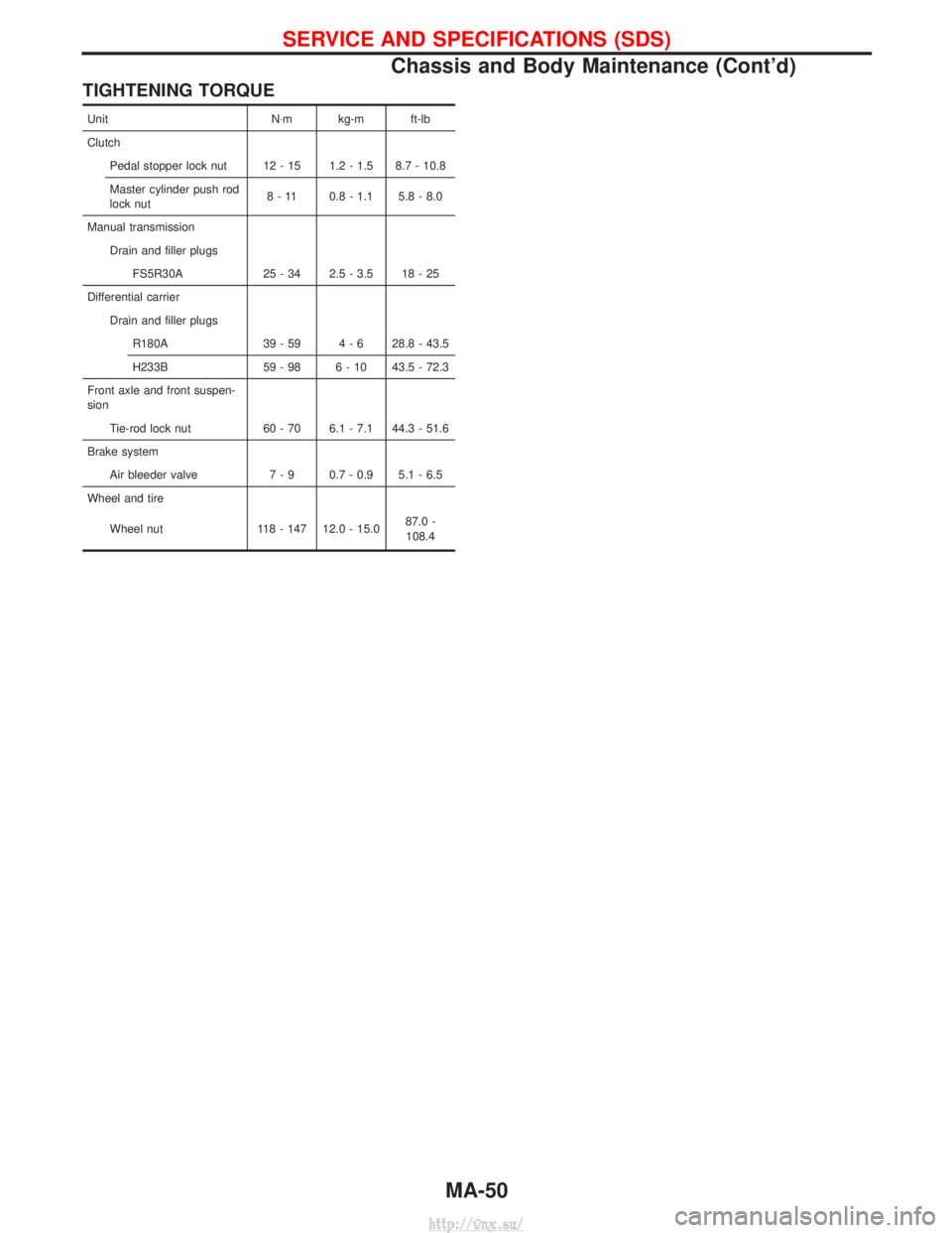
TIGHTENING TORQUE
UnitN×m kg-m ft-lb
Clutch Pedal stopper lock nut 12 - 15 1.2 - 1.5 8.7 - 10.8
Master cylinder push rod
lock nut 8 - 11 0.8 - 1.1 5.8 - 8.0
Manual transmission Drain and filler plugsFS5R30A 25 - 34 2.5 - 3.5 18 - 25
Differential carrier Drain and filler plugsR180A 39 - 59 4 - 6 28.8 - 43.5
H233B 59 - 98 6 - 10 43.5 - 72.3
Front axle and front suspen-
sion Tie-rod lock nut 60 - 70 6.1 - 7.1 44.3 - 51.6
Brake system Air bleeder valve 7 - 9 0.7 - 0.9 5.1 - 6.5
Wheel and tire
Wheel nut 118 - 147 12.0 - 15.0 87.0 -
108.4
SERVICE AND SPECIFICATIONS (SDS)
Chassis and Body Maintenance (Cont'd)
MA-50
http://vnx.su/
Page 158 of 1833
Selection Procedure for Selective Part
Combination
LocationSelective part combination ItemMethod
Cylinder block - piston Piston and piston assembly
(Part No. is given to a piston and piston pin as a set.) Piston grade (Piston outer
diameter) Refer to ªSelective combination
chartº.
IIdentification grade stamped on each part represents initial
dimension of new part. This grade will not be applied to a
reused part.
I Measure correct dimensions of a reused or modified part, then
refer to ªSelective combination chartº in this manual to identify
the grade.
I Refer to the applicable pages for measurement method for
each part, standards for reuse, and selecting method for selec-
tive part combination.
Disassembly
1. Remove engine assembly from vehicle.
Refer to EM-63, ªENGINE REMOVALº.
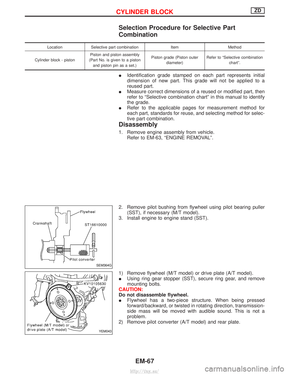
2. Remove pilot bushing from flywheel using pilot bearing puller (SST), if necessary (M/T model).
3. Install engine to engine stand (SST).
1) Remove flywheel (M/T model) or drive plate (A/T model).
I Using ring gear stopper (SST), secure ring gear, and remove
mounting bolts.
CAUTION:
Do not disassemble flywheel.
I Flywheel has a two-piece structure. When being pressed
forward/backward, or twisted in rotating direction, transmission-
side mass will be moved with audible sound. This is not a
problem.
2) Remove pilot converter (A/T model) and rear plate.
SEM364G
YEM043
CYLINDER BLOCKZD
EM-67
http://vnx.su/
Page 778 of 1833

MANUAL TRANSMISSIONSECTION
MT
CONTENTS
PREPARATION ................................................................2
Special Service Tools ..................................................2
Commercial Service Tools ...........................................4
TRANSMISSION FS5R30A .............................................5
Replacing the Rear Oil Seal ........................................5
FS5R30A
ON-VEHICLE SERVICE ..................................................6
Check of Position Switches .........................................6
REMOVAL AND INSTALLATION ....................................7
Removal .......................................................................7
Installation ....................................................................8
MAJOR OVERHAUL .....................................................10
Case Components .....................................................10
Gear Components ..................................................... 11 Shift Control Components .........................................13
DISASSEMBLY ..............................................................14
Case Components .....................................................14
Shift Control Components .........................................15
Gear Components .....................................................16
INSPECTION..................................................................21 Shift Control Components .........................................21
Gear Components .....................................................21
ASSEMBLY ....................................................................23
Gear Components .....................................................23
Shift Control Components .........................................31
Case Components .....................................................32
SERVICE DATA AND SPECIFICATIONS (SDS) ..........34
General Specifications ...............................................34
Inspection and Adjustment ........................................35
http://vnx.su/
Page 817 of 1833
Supplemental Restraint System (SRS) ªAIR
BAGº and ªSEAT BELT PRE-TENSIONERº
The Supplemental Restraint System such as ªAIR BAGº and ªSEAT BELT PRE-TENSIONERº used along with
a seat belt, helps to reduce the risk or severity of injury to the driver and front passenger for certain types of
collision. The SRS composition which is available to NISSAN MODEL R20 is as follows (The composition
varies according to the destination and optional equipment.):
IFor a frontal collision
The Supplemental Restraint System consists of driver air bag module (located in the center of the steer-
ing wheel), front passenger air bag module (located on the instrument panel on passenger side), front seat
belt pre-tensioners, a diagnosis sensor unit, warning lamp, wiring harness and spiral cable.
I For a side collision
The Supplemental Restraint System consists of front side air bag module (located in the outer side of front
seat), side air bag (satellite) sensor, diagnosis sensor unit (one of components of air bags for a frontal
collision), wiring harness, warning lamp (one of components of air bags for a frontal collision).
WARNING:
I To avoid rendering the SRS inoperative, which could increase the risk of personal injury or death
in the event of a collision which would result in air bag inflation, all maintenance should be per-
formed by an authorized NISSAN dealer.
I Improper maintenance, including incorrect removal and installation of the SRS, can lead to per-
sonal injury caused by unintentional activation of the system.
I Do not use electrical test equipment on any circuit related to the SRS unless instructed to in this
Service Manual. Spiral cable and wiring harnesses covered with yellow insulation tape either just
before the harness connectors or for the complete harness are related to the SRS.
Precautions for SRS ªAIR BAGº and ªSEAT
BELT PRE-TENSIONERº Service
IDo not use electrical test equipment to check SRS circuits unless instructed to in this Service Manual.
I Before servicing the SRS, turn ignition switch ªOFFº, disconnect both battery cables and wait at least 3
minutes.
For approximately 3 minutes after the cables are removed, it is still possible for the air bag and seat belt
pre-tensioner to deploy. Therefore, do not work on any SRS connectors or wires until at least 3 minutes
have passed.
I Diagnosis sensor unit must always be installed with their arrow marks ª +º pointing towards the front of
the vehicle for proper operation. Also check diagnosis sensor unit for cracks, deformities or rust before
installation and replace as required.
I The spiral cable must be aligned with the neutral position since its rotations are limited. Do not attempt to
turn steering wheel or column after removal of steering gear.
I Handle air bag module carefully. Always place driver and front passenger air bag modules with the pad
side facing upward and place front side air bag module (built-in type) standing with stud bolt side setting
bottom.
I Conduct self-diagnosis to check entire SRS for proper function after replacing any components.
I After air bag inflates, the front instrument panel assembly should be replaced if damaged.
Precautions
IBefore proceeding with disassembly, thoroughly clean the outside of the transmission. It is important to
prevent the internal parts from becoming contaminated by dirt or other foreign matter.
I Disassembly should be done in a clean work area.
I Use lint-free cloth or towels for wiping parts clean. Common shop rags can leave fibers that could inter-
fere with the operation of the transmission.
I Place disassembled parts in order for easier and proper assembly.
I All parts should be carefully cleaned with a general purpose, non-flammable solvent before inspection or
reassembly.
I Gaskets, seals and O-rings should be replaced any time the transmission is disassembled.
I It is very important to perform functional tests whenever they are indicated.
I The valve body contains precision parts and requires extreme care when parts are removed and serviced.
Place removed parts in a parts rack in order to replace them in correct positions and sequences. Care will
also prevent springs and small parts from becoming scattered or lost.
I Properly installed valves, sleeves, plugs, etc. will slide along bores in valve body under their own weight.
PREPARATION AND PRECAUTIONS
AT- 4
http://vnx.su/
Page 932 of 1833
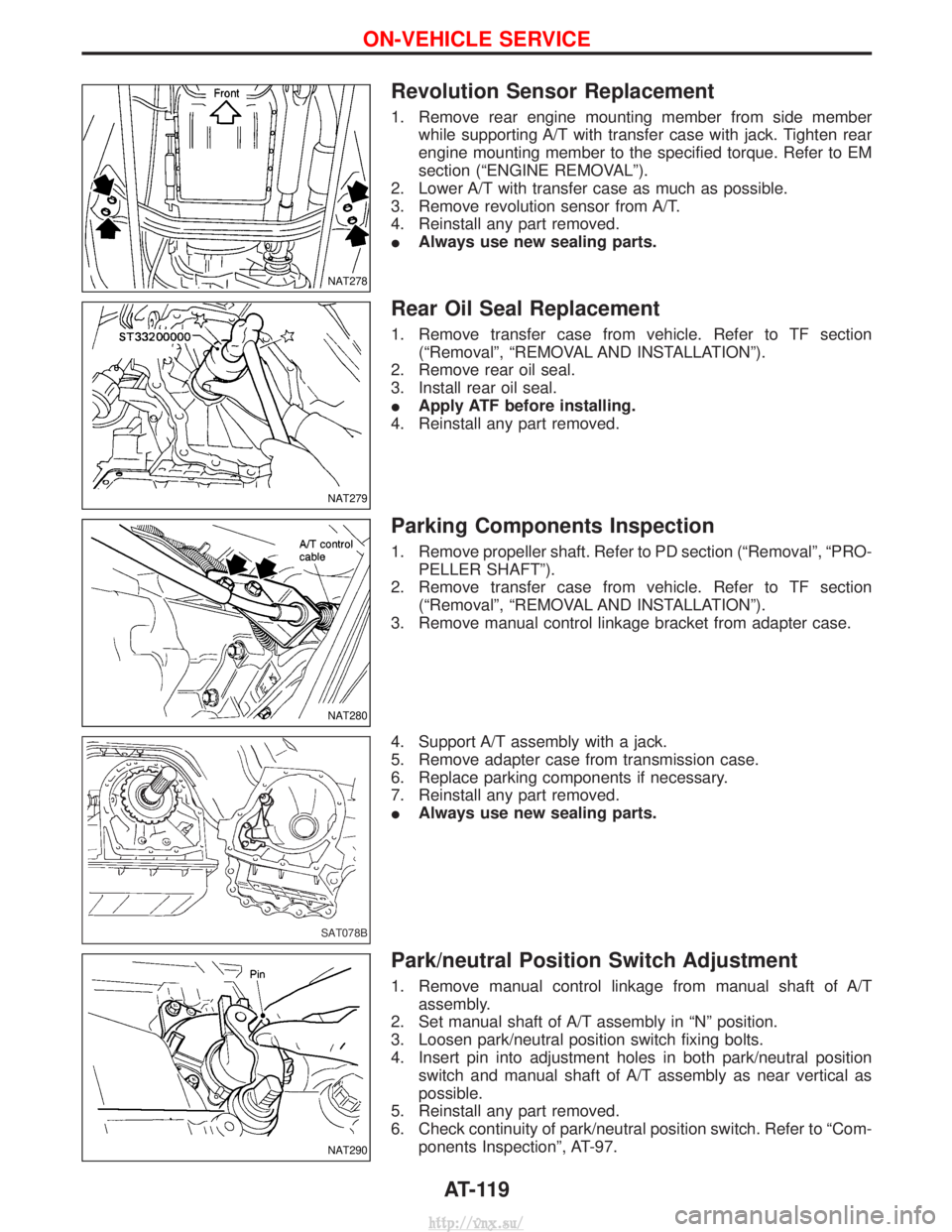
Revolution Sensor Replacement
1. Remove rear engine mounting member from side memberwhile supporting A/T with transfer case with jack. Tighten rear
engine mounting member to the specified torque. Refer to EM
section (ªENGINE REMOVALº).
2. Lower A/T with transfer case as much as possible.
3. Remove revolution sensor from A/T.
4. Reinstall any part removed.
I Always use new sealing parts.
Rear Oil Seal Replacement
1. Remove transfer case from vehicle. Refer to TF section
(ªRemovalº, ªREMOVAL AND INSTALLATIONº).
2. Remove rear oil seal.
3. Install rear oil seal.
I Apply ATF before installing.
4. Reinstall any part removed.
Parking Components Inspection
1. Remove propeller shaft. Refer to PD section (ªRemovalº, ªPRO- PELLER SHAFTº).
2. Remove transfer case from vehicle. Refer to TF section (ªRemovalº, ªREMOVAL AND INSTALLATIONº).
3. Remove manual control linkage bracket from adapter case.
4. Support A/T assembly with a jack.
5. Remove adapter case from transmission case.
6. Replace parking components if necessary.
7. Reinstall any part removed.
I Always use new sealing parts.
Park/neutral Position Switch Adjustment
1. Remove manual control linkage from manual shaft of A/T
assembly.
2. Set manual shaft of A/T assembly in ªNº position.
3. Loosen park/neutral position switch fixing bolts.
4. Insert pin into adjustment holes in both park/neutral position switch and manual shaft of A/T assembly as near vertical as
possible.
5. Reinstall any part removed.
6. Check continuity of park/neutral position switch. Refer to ªCom- ponents Inspectionº, AT-97.
NAT278
NAT279
NAT280
SAT078B
NAT290
ON-VEHICLE SERVICE
AT-119
http://vnx.su/
Page 943 of 1833
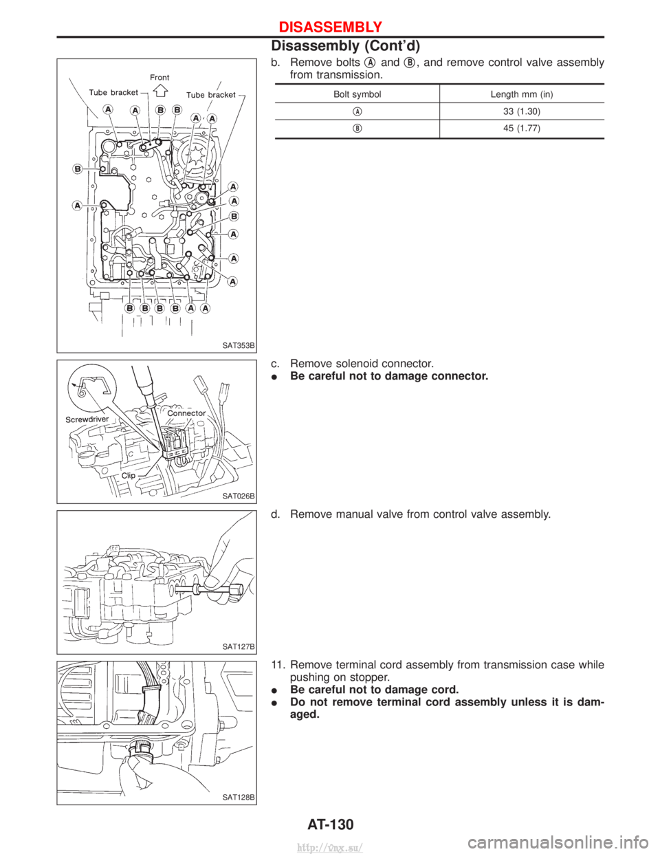
b. Remove boltsqAandqB, and remove control valve assembly
from transmission.
Bolt symbol Length mm (in)
q
A33 (1.30)
q
B45 (1.77)
c. Remove solenoid connector.
I Be careful not to damage connector.
d. Remove manual valve from control valve assembly.
11. Remove terminal cord assembly from transmission case while pushing on stopper.
I Be careful not to damage cord.
I Do not remove terminal cord assembly unless it is dam-
aged.
SAT353B
SAT026B
SAT127B
SAT128B
DISASSEMBLY
Disassembly (Cont'd)
AT-130
http://vnx.su/