Page 1759 of 1833

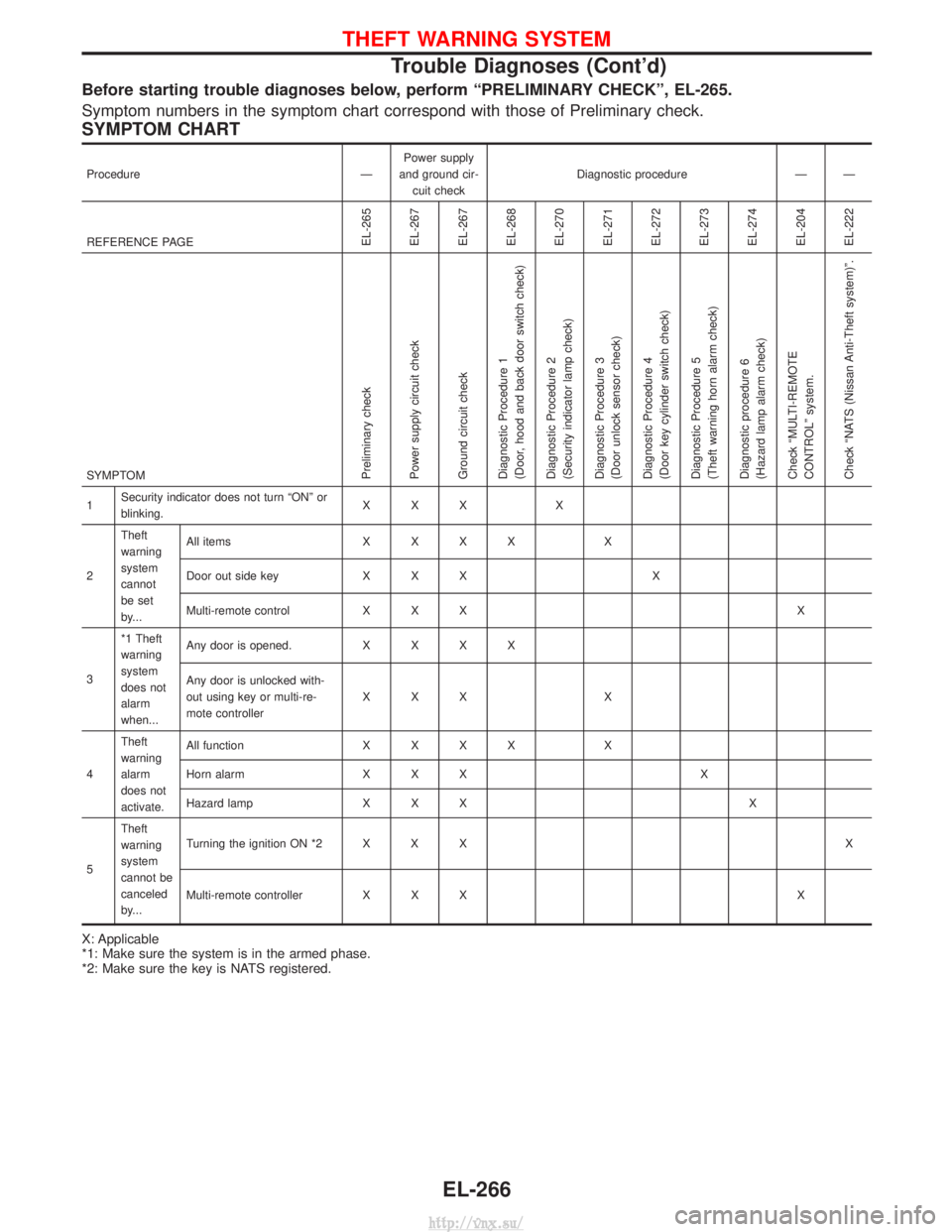
Before starting trouble diagnoses below, perform ªPRELIMINARY CHECKº, EL-265.
Symptom numbers in the symptom chart correspond with those of Preliminary check.
SYMPTOM CHART
ProcedureÐPower supply
and ground cir- cuit check Diagnostic procedure Ð Ð
REFERENCE PAGE
EL-265
EL-267
EL-267
EL-268
EL-270
EL-271
EL-272
EL-273
EL-274
EL-204
EL-222
SYMPTOMPreliminary check
Power supply circuit check
Ground circuit check
Diagnostic Procedure 1
(Door, hood and back door switch check)
Diagnostic Procedure 2
(Security indicator lamp check)
Diagnostic Procedure 3
(Door unlock sensor check)
Diagnostic Procedure 4
(Door key cylinder switch check)
Diagnostic Procedure 5
(Theft warning horn alarm check)
Diagnostic procedure 6
(Hazard lamp alarm check)
Check ªMULTI-REMOTE
CONTROLº system.
Check ªNATS (Nissan Anti-Theft system)º.
1 Security indicator does not turn ªONº or
blinking. XXX X
2 Theft
warning
system
cannot
be set
by... All items
XXXX X
Door out side key X X X X
Multi-remote control X X X X
3 *1 Theft
warning
system
does not
alarm
when... Any door is opened.
XXXX
Any door is unlocked with-
out using key or multi-re-
mote controller XXX
X
4 Theft
warning
alarm
does not
activate. All function
XXXX X
Horn alarm X X X X
Hazard lamp X X X X
5 Theft
warning
system
cannot be
canceled
by... Turning the ignition ON *2 X X X
X
Multi-remote controller X X X X
X: Applicable
*1: Make sure the system is in the armed phase.
*2: Make sure the key is NATS registered.
THEFT WARNING SYSTEM
Trouble Diagnoses (Cont'd)
EL-266
http://vnx.su/
Page 1766 of 1833

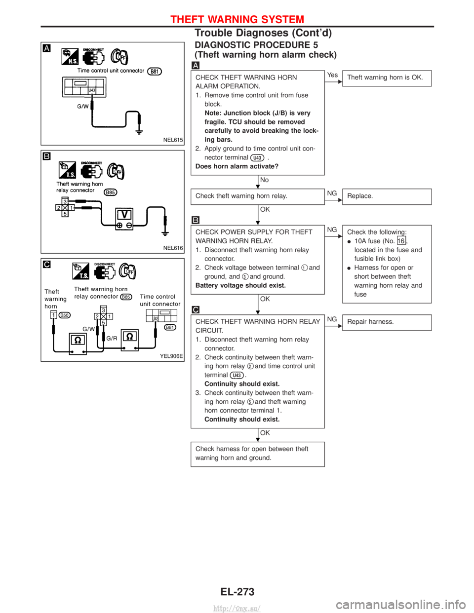
DIAGNOSTIC PROCEDURE 5
(Theft warning horn alarm check)
CHECK THEFT WARNING HORN
ALARM OPERATION.
1. Remove time control unit from fuseblock.
Note: Junction block (J/B) is very
fragile. TCU should be removed
carefully to avoid breaking the lock-
ing bars.
2. Apply ground to time control unit con- nector terminal
U43.
Does horn alarm activate?
No
EYe s Theft warning horn is OK.
Check theft warning horn relay.
OK
ENGReplace.
CHECK POWER SUPPLY FOR THEFT
WARNING HORN RELAY.
1. Disconnect theft warning horn relay
connector.
2. Check voltage between terminal q
1and
ground, and q
3and ground.
Battery voltage should exist.
OK
ENG Check the following:
I10A fuse (No.
16 ,
located in the fuse and
fusible link box)
I Harness for open or
short between theft
warning horn relay and
fuse
CHECK THEFT WARNING HORN RELAY
CIRCUIT.
1. Disconnect theft warning horn relay
connector.
2. Check continuity between theft warn- ing horn relay q
2and time control unit
terminal
U43.
Continuity should exist.
3. Check continuity between theft warn- ing horn relay q
5and theft warning
horn connector terminal 1.
Continuity should exist.
OK
ENG Repair harness.
Check harness for open between theft
warning horn and ground.
NEL615
NEL616
YEL906E
H
H
H
H
THEFT WARNING SYSTEM
Trouble Diagnoses (Cont'd)
EL-273
http://vnx.su/
Page 1767 of 1833
DIAGNOSTIC PROCEDURE 6
(Hazard lamp alarm check)
Push hazard switch to ON.
Check hazard lamp operation.
NG
EOKReplace time control unit.
1. Remove time control unit from fuse
block (J/B).
Note: Junction block (J/B) is very
fragile. TCU should be removed
carefully to avoid breaking the lock-
ing bars.
2. Check harness continuity between fuse block (J/B) terminals
U11and
U15and ground.
Continuity should exist.
OK
ENG Check the following.
IHarness connectors
I Fuse block (J/B)
I Turn signal lamps
I Harness between time
control unit and turn sig-
nal lamps, turn signal
lamps and ground.
Replace time control unit.
NEL618
H
H
THEFT WARNING SYSTEM
Trouble Diagnoses (Cont'd)
EL-274
http://vnx.su/