Page 20 of 320
Seat lifter (if so equipped for driver’s
seat)
Turn either dial to adjust the angle and height of
the seat cushion to the desired position.
Lumbar support (driver’s seat)
The lumbar support feature provides lower back
support to the driver. Move the lever up or down
to adjust the seat lumbar area.
WRS0131LRS0278
1-4Safety—Seats, seat belts and supplemental air bags
ZREVIEW COPY:Ð2004 Quest(van)
Owners Manual(owners)ÐUSA English(nna)
10/08/03Ðtbrooks
X
Page 22 of 320
Seat lifter (if so equipped for driver’s
seat)
Push the front or rear end of the switch up or
down to adjust the angle and height of the seat
cushion.
Lumbar support (driver’s seat)
The lumbar support feature provides lower back
support to the driver. Move the lever up or down
to adjust the seat lumbar area.
2ND ROW CAPTAIN’S CHAIR
ADJUSTMENT
Forward and backward
Pull the lever ups1and hold it while you slides2
the seat forward or backward to the desired
position. Release the lever to lock the seat in
position.
WRS0277LRS0278LRS0279
1-6Safety—Seats, seat belts and supplemental air bags
ZREVIEW COPY:Ð2004 Quest(van)
Owners Manual(owners)ÐUSA English(nna)
10/08/03Ðtbrooks
X
Page 55 of 320

cWhen attaching the rear center seat
belt connector, be certain that the seat-
backs are completely secured in the
latched position and the rear center
seat belt connector is completely
secured.
cIf the rear center seat belt connector
and the seatbacks are not secured in
the correct position, serious personal
injury may result in an accident or sud-
den stop.
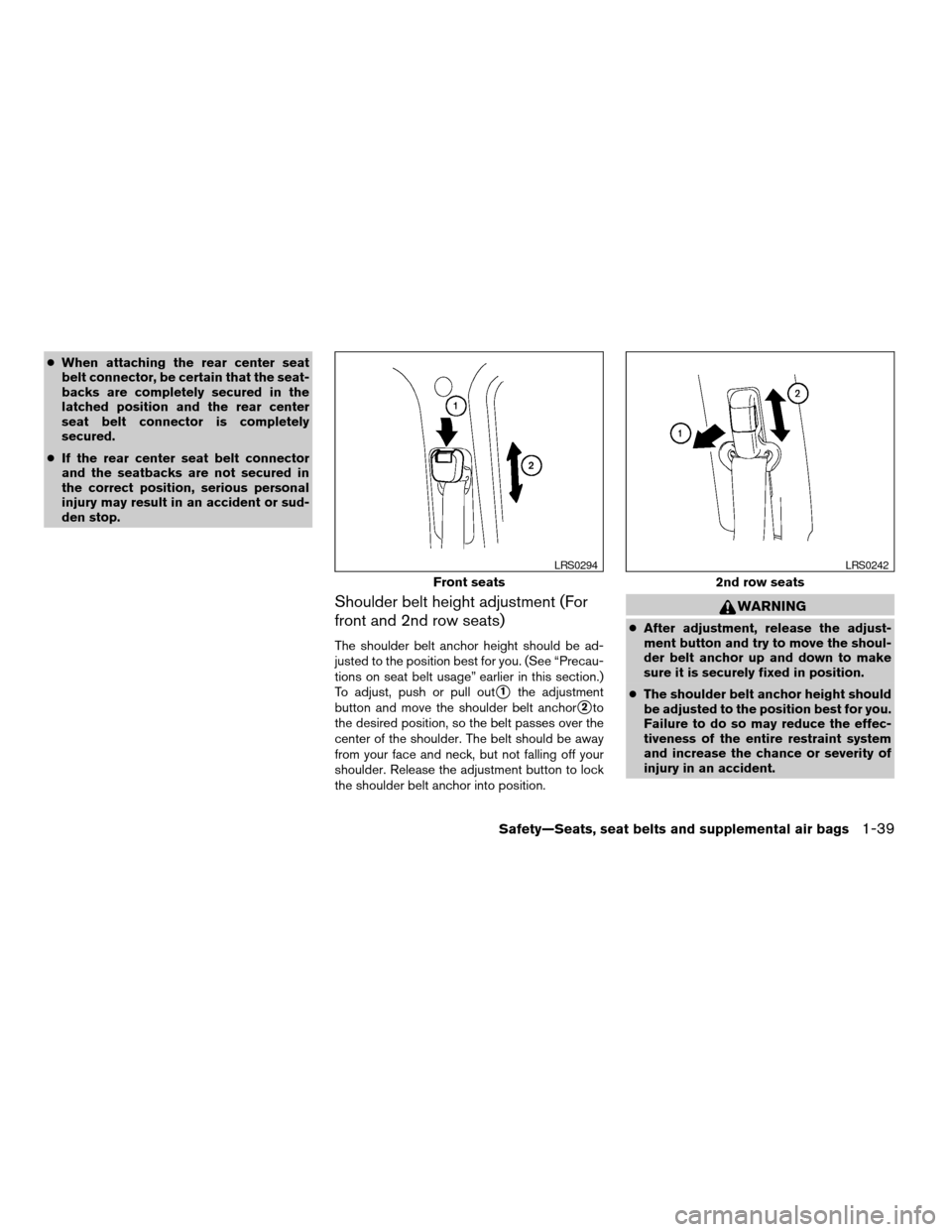
Shoulder belt height adjustment (For
front and 2nd row seats)
The shoulder belt anchor height should be ad-
justed to the position best for you. (See “Precau-
tions on seat belt usage” earlier in this section.)
To adjust, push or pull out
s1the adjustment
button and move the shoulder belt anchor
s2to
the desired position, so the belt passes over the
center of the shoulder. The belt should be away
from your face and neck, but not falling off your
shoulder. Release the adjustment button to lock
the shoulder belt anchor into position.
WARNING
cAfter adjustment, release the adjust-
ment button and try to move the shoul-
der belt anchor up and down to make
sure it is securely fixed in position.
cThe shoulder belt anchor height should
be adjusted to the position best for you.
Failure to do so may reduce the effec-
tiveness of the entire restraint system
and increase the chance or severity of
injury in an accident.
Front seats
LRS0294
2nd row seats
LRS0242
Safety—Seats, seat belts and supplemental air bags1-39
ZREVIEW COPY:Ð2004 Quest(van)
Owners Manual(owners)ÐUSA English(nna)
10/08/03Ðtbrooks
X
Page 268 of 320

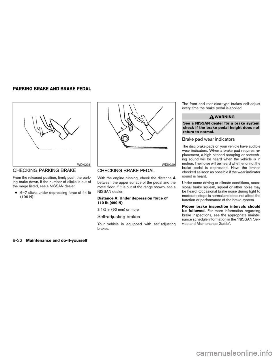
CHECKING PARKING BRAKE
From the released position, firmly push the park-
ing brake down. If the number of clicks is out of
the range listed, see a NISSAN dealer.
c6–7 clicks under depressing force of 44 lb
(196 N) .
CHECKING BRAKE PEDAL
With the engine running, check the distanceA
between the upper surface of the pedal and the
metal floor. If it is out of the range shown, see a
NISSAN dealer.
Distance A: Under depression force of
110 lb (490 N)
3 1/2 in (90 mm) or more
Self-adjusting brakes
Your vehicle is equipped with self-adjusting
brakes.The front and rear disc-type brakes self-adjust
every time the brake pedal is applied.
WARNING
See a NISSAN dealer for a brake system
check if the brake pedal height does not
return to normal.
Brake pad wear indicators
The disc brake pads on your vehicle have audible
wear indicators. When a brake pad requires re-
placement, a high pitched scraping or screech-
ing sound will be heard when the vehicle is in
motion. The noise will be heard whether or not the
brake pedal is depressed. Have the brakes
checked as soon as possible if the wear indicator
sound is heard.
Under some driving or climate conditions, occa-
sional brake squeak, squeal or other noise may
be heard. Occasional brake noise during light to
moderate stops is normal and does not affect the
function or performance of the brake system.
Proper brake inspection intervals should
be followed.For more information regarding
brake inspections, see the appropriate mainte-
nance schedule information in the “NISSAN Ser-
vice and Maintenance Guide”.
WDI0293WDI0229
PARKING BRAKE AND BRAKE PEDAL
8-22Maintenance and do-it-yourself
ZREVIEW COPY:Ð2004 Quest(van)
Owners Manual(owners)ÐUSA English(nna)
10/08/03Ðtbrooks
X
Page 269 of 320

BRAKE BOOSTER
Check the brake booster function as follows:
1. With the engine off, press and release the
brake pedal several times. When brake
pedal movement (distance of travel) remains
the same from one pedal application to the
next, continue on to the next step.
2. While depressing the brake pedal, start the
engine. The pedal height should drop a little.
3. With the brake pedal depressed, stop the
engine. Keep the pedal depressed for about
30 seconds. The pedal height should not
change.
4. Run the engine for one minute without de-
pressing the brake pedal, then turn it off.
Depress the brake pedal several times. The
pedal travel distance will decrease gradually
with each depression as the vacuum is re-
leased from the booster.
If the brakes do not operate properly, have the
brakes checked by a NISSAN dealer.
ENGINE COMPARTMENT
CAUTION
Never use a fuse of a higher or lower
amperage rating than specified on the
fuse box cover. This could damage the
electrical system or cause a fire.
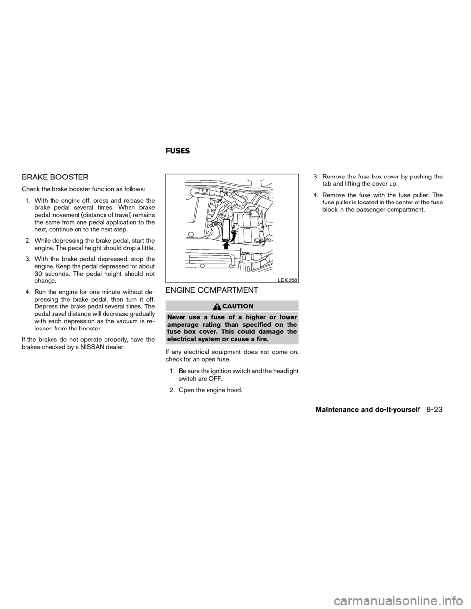
If any electrical equipment does not come on,
check for an open fuse.
1. Be sure the ignition switch and the headlight
switch are OFF.
2. Open the engine hood.3. Remove the fuse box cover by pushing the
tab and lifting the cover up.
4. Remove the fuse with the fuse puller. The
fuse puller is located in the center of the fuse
block in the passenger compartment.
LDI0358
FUSES
Maintenance and do-it-yourself8-23
ZREVIEW COPY:Ð2004 Quest(van)
Owners Manual(owners)ÐUSA English(nna)
10/08/03Ðtbrooks
X
Page 280 of 320
(1) Tire size (example: P215/65R15 95H)
1. P: The9P9indicates the tire is designed for
passenger vehicles.
2. Three-digit number: This number gives the
width in millimeters of the tire from sidewall
edge to sidewall edge.
3. Two-digit number: This number, known as
the aspect ratio, gives the tire’s ratio of
height to width.
4. R: The9R9stands for radial.
5. Two-digit number: This number is the wheel
or rim diameter in inches.6. Two- or three-digit number: This number is
the tire’s load index. It is a measurement of
how much weight each tire can support. You
may not find this information on all tires be-
cause it is not required by law.
7. Tire speed rating. You should not drive the
vehicle faster than the tire speed rating.
WDI0395
8-34Maintenance and do-it-yourself
ZREVIEW COPY:Ð2004 Quest(van)
Owners Manual(owners)ÐUSA English(nna)
10/08/03Ðtbrooks
X
Page 284 of 320

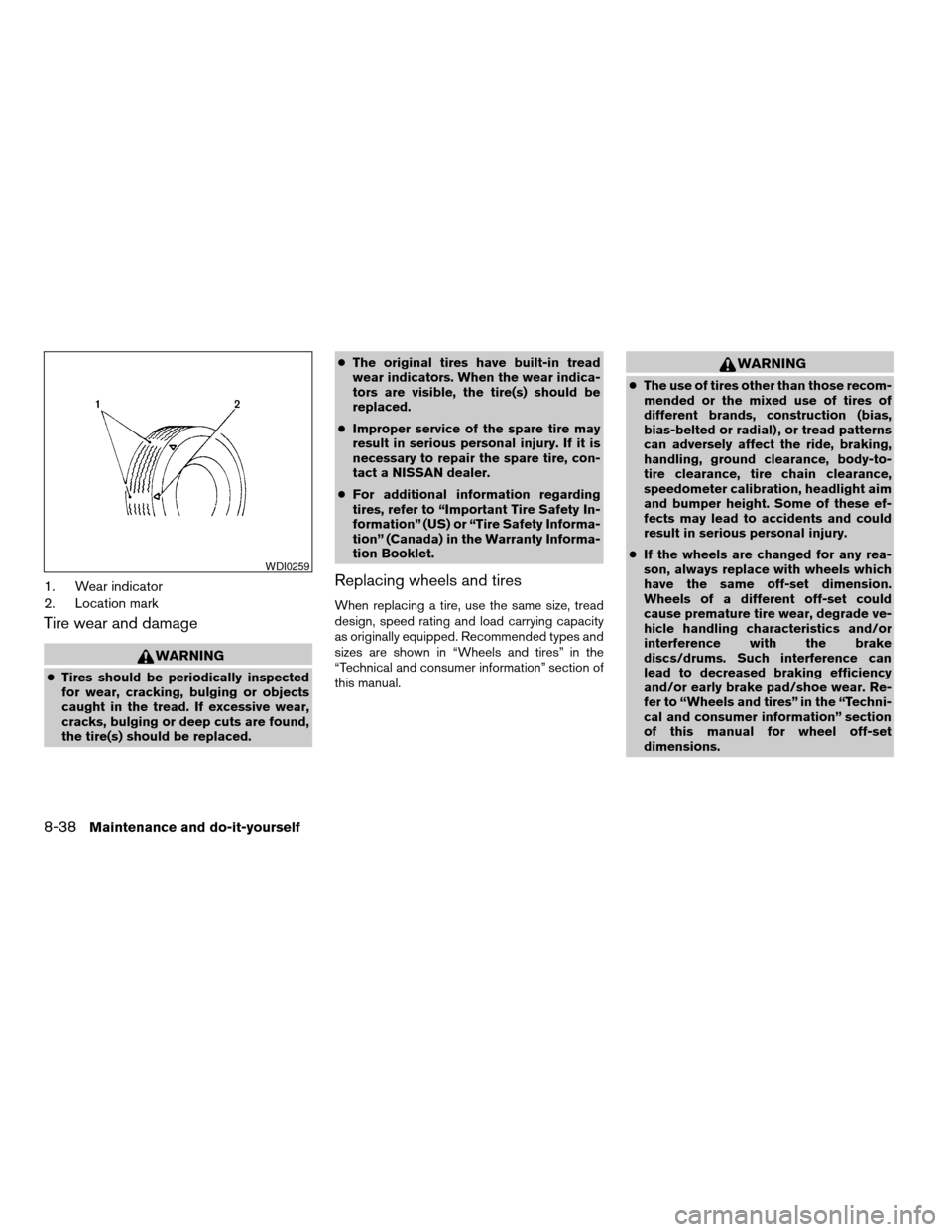
1. Wear indicator
2. Location mark
Tire wear and damage
WARNING
cTires should be periodically inspected
for wear, cracking, bulging or objects
caught in the tread. If excessive wear,
cracks, bulging or deep cuts are found,
the tire(s) should be replaced.cThe original tires have built-in tread
wear indicators. When the wear indica-
tors are visible, the tire(s) should be
replaced.
cImproper service of the spare tire may
result in serious personal injury. If it is
necessary to repair the spare tire, con-
tact a NISSAN dealer.
cFor additional information regarding
tires, refer to “Important Tire Safety In-
formation” (US) or “Tire Safety Informa-
tion” (Canada) in the Warranty Informa-
tion Booklet.
Replacing wheels and tires
When replacing a tire, use the same size, tread
design, speed rating and load carrying capacity
as originally equipped. Recommended types and
sizes are shown in “Wheels and tires” in the
“Technical and consumer information” section of
this manual.
WARNING
cThe use of tires other than those recom-
mended or the mixed use of tires of
different brands, construction (bias,
bias-belted or radial) , or tread patterns
can adversely affect the ride, braking,
handling, ground clearance, body-to-
tire clearance, tire chain clearance,
speedometer calibration, headlight aim
and bumper height. Some of these ef-
fects may lead to accidents and could
result in serious personal injury.
cIf the wheels are changed for any rea-
son, always replace with wheels which
have the same off-set dimension.
Wheels of a different off-set could
cause premature tire wear, degrade ve-
hicle handling characteristics and/or
interference with the brake
discs/drums. Such interference can
lead to decreased braking efficiency
and/or early brake pad/shoe wear. Re-
fer to “Wheels and tires” in the “Techni-
cal and consumer information” section
of this manual for wheel off-set
dimensions.
WDI0259
8-38Maintenance and do-it-yourself
ZREVIEW COPY:Ð2004 Quest(van)
Owners Manual(owners)ÐUSA English(nna)
10/08/03Ðtbrooks
X
Page 294 of 320
WHEELS AND TIRES
Wheels
16 x 6.5JJ
17 x 6.5JJ
Tires
P225/65R16
P225/60R17
Spare tire T135/80*16
Speed rating 16” H
17” H
*: “R” or “D” depending on tire manufacturer
DIMENSIONS AND WEIGHTS
Overall length in (mm) 204.13(5,185)
Overall width in (mm) 77.64(1,972)
Overall height
with roof rack in (mm) 71.90(1,826)
without roof rack in (mm) 70.0 (1,778)
Front tread in (mm) 67.32(1,710)
Rear tread in (mm) 67.32(1,710)
Wheelbase in (mm) 124.02(3,150)
Gross vehicle weight
ratinglb (kg)
See the “F.M.V.S.S.
certification label” on the
center pillar between the
driver’s side front and
side doors. Gross axle weight rating
Front lb (kg)
Rear lb (kg)
9-8Technical and consumer information
ZREVIEW COPY:Ð2004 Quest(van)
Owners Manual(owners)ÐUSA English(nna)
10/08/03Ðtbrooks
X