Page 1 of 53

GENERAL INFORMATIONGI
MAINTENANCEMA
ENGINE MECHANICALEM
ENGINE LUBRICATION &
COOLING SYSTEMSLC
ENGINE CONTROL SYSTEMEC
ACCELERATOR CONTROL, FUEL &
EXHAUST SYSTEMSFE
CLUTCHCL
MANUAL TRANSAXLEMT
TRANSFERTF
PROPELLER SHAFT &
DIFFERENTIAL CARRIERPD
FRONT AXLE & FRONT SUSPENSIONFA
REAR AXLE & REAR SUSPENSIONRA
BRAKE SYSTEMBR
STEERING SYSTEMST
RESTRAINT SYSTEMRS
BODY & TRIMBT
HEATER & AIR CONDITIONERHA
ELECTRICAL SYSTEMEL
ALPHABETICAL INDEXIDX
PICKUP
MODEL D22 SERIES
FOREWORD
This supplement contains informa-
tion concerning necessary service
procedures and relevant data for the
model D22 series.
All information, illustrations and spe-
ci®cations contained in this supple-
ment are based on the latest product
information available at the time of
publication. If your NISSAN model
differs from the speci®cations contain-
ed in this supplement, consult your
NISSAN distributor for information.
The right is reserved to make chan-
ges in speci®cations and methods at
any time without notice.
Edition: September 2004
Printing: September 2004 (01)
Publication No.: SM4E00-1D22E0E
Reference No.: 7711347309
NISSAN EUROPE S.A.S.
2004 NISSAN EUROPE S.A.S. Printed in the Netherlands
Not to be reproduced in whole or in part without the prior written permission of Nissan Europe S.A.S., Paris, France.
QUICK REFERENCE INDEX
Page 2 of 53

FOREWORD
This manual contains maintenance and repair procedures for NISSAN
PICKUP, model D22 series.
In order to assure your safety and the efficient functioning of the vehicle,
this manual should be read thoroughly. It is especially important that the
PRECAUTIONS in the GI section be completely understood before starting
any repair task.
All information in this manual is based on the latest product information
at the time of publication. The right is reserved to make changes in speci-
®cations and methods at any time without notice.
IMPORTANT SAFETY NOTICE
The proper performance of service is essential for both the safety of the
technician and the efficient functioning of the vehicle.
The service methods in this Service Manual are described in such a man-
ner that the service may be performed safely and accurately.
Service varies with the procedures used, the skills of the technician and the
tools and parts available. Accordingly, anyone using service procedures,
tools or parts which are not speci®cally recommended by NISSAN must
®rst completely satisfy himself that neither his safety nor the vehicle's
safety will be jeopardized by the service method selected.
NISSAN EUROPE S.A.S.
Service Engineering Section
Paris, France
Page 3 of 53
CLUTCH
SECTION
CL
MODIFICATION NOTICE:
Service data and specifications (SDS) have been changed.
CONTENTS
SERVICE DATA AND SPECIFICATIONS
(SDS).................................................................... 6002General Specifications ..................................... 6002
Inspection and Adjustment .............................. 6002
CL
Page 4 of 53

General Specifications
Engine model KA24DE VG33E YD25DDTi TD27 ZD30DDT QD32
Transmission model FS5W71C FS5R30A FS5W71C FS5R30A
Clutch model 240 250 240 250
Clutch master cylinder
Inner diameter mm (in) 15.87 (5/8)
Clutch operating cylinder
Inner diam-
eterLHD mm (in) 17.46 (11/16) Ð 19.05 (3/4) 17.46 (11/16) 19.05 (3/4) 17.46 (11/16)
RHD mm (in) 19.05 (3/4)
Clutch disc
Facing size mm (in)
(Outer dia. x inner dia. x
thickness)240 x 150 x 3.5
(9.45 x 5.91 x
0.138)250 x 160 x 3.8
(9.84 x 6.30 x
0.150)250 x 160 x 3.5
(9.84 x 6.30 x
0.138)240 x 160 x 3.5
(9.45 x 6.30 x
0.138)250 x 160 x 3.5
(9.84 x 6.30 x
0.138)250 x 160 x 3.5
(9.84 x 6.30 x
0.138)
Thickness of disc assembly 8.1 (0.319) 8.3 (0.327) 8.1 (0.319) 7.8 (0.307) 8.1 (0.319)
With load mm (in)With 4,903 N
(500 kg, 1,103 lb)With 6,472 N
(660 kg, 1,455 lb)With 7,350 N
(750 kg, 1,652 lb)With 4,903 N
(500 kg, 1,103 lb)With 7,350 N
(750 kg, 1,652 lb)With 5,884 N
(600 kg, 1,323 lb)
Clutch cover
Full load2WD
N (kg, lb)4,903 (500,
1,103)Ð7,360 (751,
1,655)3,923 (400, 882) Ð Ð
4WD
N (kg, lb)4,659 (475,
1,047)6,472 (660,
1,455)7,360 (751,
1,655)Ð7,360 (751,
1,655)5,394 (550,
1,213)
Inspection and Adjustment
Engine model KA24DE VG33E YD25DDTi TD27 ZD30DDT QD32
Clutch model 240 250 240 250
Clutch disc
Wear limit of facing surface
to rivet head mm (in)0.3 (0.012)
Runout limit of facing
mm (in)1.0 (0.039) 0.7 (0.028) 1.0 (0.039) 0.7 (0.028)
Distance of runout check
point (from the hub center)
mm (in)115 (4.53) 120 (4.72) 120 (4.72) 115 (4.53) 120 (4.72)
Maximum backlash of spline
(at outer edge of disc)
mm (in)1.0 (0.039)
Clutch cover
Diaphragm spring height
mm (in)38.5 (1.516) 37.5 (1.476) 40.5 (1.594) 38.5 (1.516) 40.5 (1.594) 38.5 (1.516)
Uneven limit of diaphragm
spring toe height mm (in)0.7 (0.028)
SERVICE DATA AND SPECIFICATIONS (SDS)
CL-6002
Page 23 of 53

ENGINE MECHANICAL
SECTION
EM
MODIFICATION NOTICE:
+Valve lifter of ZD30DDT engine has been changed from a type without shim to a type with adjusting shim.
For information not included here, refer to information for ZD30DDT engines in NISSAN model D22 series
SERVICE MANUAL Supplement-V (Publication No. SM3E00-1D22E0E).
CONTENTS
PREPARATION................................................... 6002
Special Service Tools ...................................... 6002
ZD
CAMSHAFT......................................................... 6003
Removal and Installation ................................. 6003
Inspection ......................................................... 6004
VALVE CLEARANCE INSPECTIONS AND
ADJUSTMENTS................................................... 6005Adjustments ..................................................... 6005
CYLINDER HEAD................................................ 6008
Disassembly and Assembly ............................. 6008
SERVICE DATA AND SPECIFICATIONS
(SDS).................................................................... 6009
Valve ................................................................ 6009
EM
Page 24 of 53
Special Service Tools
Tool number
Tool nameDescription
KV101151S0
Lifter stopper set
V1KV10115110
Camshaft pliers
V2KV10115120
Lifter stopper
NT041
Changing adjusting shims
PREPARATION
EM-6002
Page 27 of 53

Adjustments
NOTE:
Adjust valve clearance while engine is cold.
+Remove the adjusting shim for parts which are outside the
specified valve clearance.
1. Remove the spill tube. Refer to ªBASIC SERVICE PROCE-
DUREº in EC section.
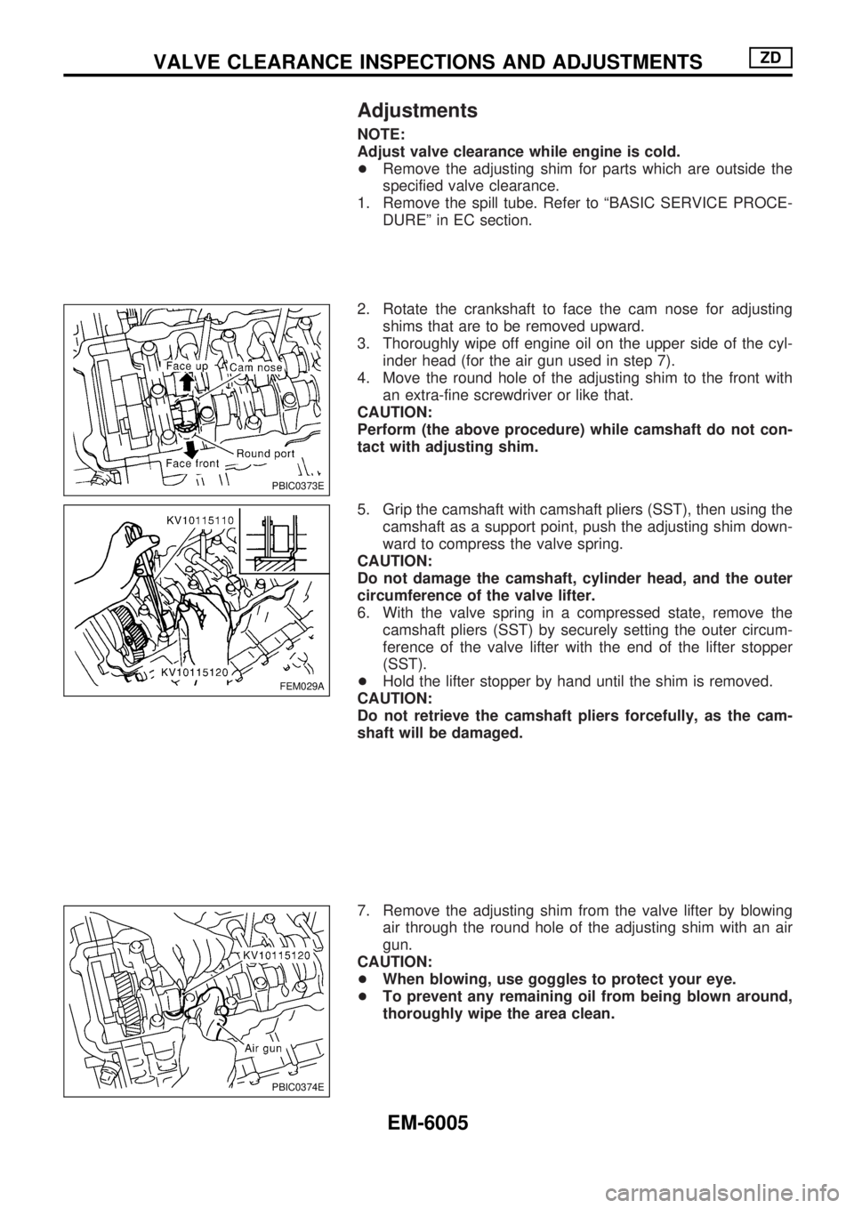
2. Rotate the crankshaft to face the cam nose for adjusting
shims that are to be removed upward.
3. Thoroughly wipe off engine oil on the upper side of the cyl-
inder head (for the air gun used in step 7).
4. Move the round hole of the adjusting shim to the front with
an extra-fine screwdriver or like that.
CAUTION:
Perform (the above procedure) while camshaft do not con-
tact with adjusting shim.
5. Grip the camshaft with camshaft pliers (SST), then using the
camshaft as a support point, push the adjusting shim down-
ward to compress the valve spring.
CAUTION:
Do not damage the camshaft, cylinder head, and the outer
circumference of the valve lifter.
6. With the valve spring in a compressed state, remove the
camshaft pliers (SST) by securely setting the outer circum-
ference of the valve lifter with the end of the lifter stopper
(SST).
+Hold the lifter stopper by hand until the shim is removed.
CAUTION:
Do not retrieve the camshaft pliers forcefully, as the cam-
shaft will be damaged.
7. Remove the adjusting shim from the valve lifter by blowing
air through the round hole of the adjusting shim with an air
gun.
CAUTION:
+When blowing, use goggles to protect your eye.
+To prevent any remaining oil from being blown around,
thoroughly wipe the area clean.
PBIC0373E
FEM029A
PBIC0374E
VALVE CLEARANCE INSPECTIONS AND ADJUSTMENTSZD
EM-6005
Page 31 of 53
Valve
VALVE CLEARANCE
Unit: mm (in)
ItemsCold*
Intake and exhaust0.30 - 0.40 (0.012 - 0.016)
*: Approximately 20ÉC (68ÉF)
AVAILABLE SHIMS
Thickness mm (in) Identification mark
2.35 (0.0925) 2.35
2.40 (0.0945) 2.40
2.45 (0.0965) 2.45
2.50 (0.0984) 2.50
2.55 (0.1004) 2.55
2.60 (0.1024) 2.60
2.65 (0.1043) 2.65
2.70 (0.1063) 2.70
2.75 (0.1083) 2.75
2.80 (0.1102) 2.80
2.85 (0.1122) 2.85
2.90 (0.1142) 2.90
2.95 (0.1161) 2.95
3.00 (0.1181) 3.00
3.05 (0.1201) 3.05
JEM184G
VALVE LIFTER
Unit: mm (in)
Valve lifter outer diameter 34.450 - 34.465 (1.3563 - 1.3569)
Lifter guide inner diameter 34.495 - 34.515 (1.3581 - 1.3589)
Clearance between lifter and lifter guide 0.030 - 0.065 (0.0012 - 0.0026)
SERVICE DATA AND SPECIFICATIONS (SDS)ZD
EM-6009