2004 NISSAN PATROL magnet clutch control
[x] Cancel search: magnet clutch controlPage 480 of 579

HEATER&
AIR CONDITIONER
SECTION
HA
MODIFICATION NOTICE:
+ Wiring diagram has been changed.
+ Automatic A/C controller has been changed.
+ Front thermo amp. for auto A/C has been eliminated.
CONTENTS
AUTO
DESCRIPTION ...........................................................4002
Features (TB48 Engine Models) ...........................4002
REAR HEATER
TROUBLE DIAGNOSES ...........................................4003
Wiring Diagram Ð R/HEAT Ð/LHD Models .........4003
Wiring Diagram Ð R/HEAT Ð/RHD Models .........4004
MANUAL
TROUBLE DIAGNOSES ...........................................4005
Wiring Diagram Ð A/C, M Ð/Wagon and
Hardtop Models with ZD Engine ...........................4005
AUTO
DESCRIPTION...........................................................4007
Control Operation ..................................................4007
TROUBLE DIAGNOSES ...........................................4008
Circuit Diagram Ð A/C, A Ð/TB48 Engine ...........4008
Wiring Diagram Ð A/C, A Ð/TB48 Engine ...........4009
Circuit Diagram Ð A/C, A Ð/TB45 Engine ...........4013
Wiring Diagram Ð A/C, A Ð/TB45 Engine ...........4014
Circuit Diagram Ð A/C, A Ð/TD Engine ...............4017
Wiring Diagram Ð A/C, A Ð/TD Engine ...............4018
Circuit Diagram Ð A/C, A Ð/ZD Engine ...............4021
Wiring Diagram Ð A/C, A Ð/ZD Engine ...............4022
Self-diagnosis ........................................................4025
Operational Check .................................................4032
A/C System ............................................................4034 Mode Door Motor...................................................4035
Air Mix Door Motor ................................................4036
Intake Door Motor ..................................................4037
Blower Motor..........................................................4038
Magnet Clutch........................................................4039
Insufficient Cooling ................................................4052
Insufficient Heating ................................................4053
Self-diagnosis ........................................................4054
REAR COOLER
TROUBLE DIAGNOSES ...........................................4055
Wiring Diagram Ð R/COOL Ð/LHD Models with
Front Auto A/C .......................................................4055
Wiring Diagram Ð R/COOL Ð/LHD Models with
Front Manual A/C Except for TB45E Engine ........4057
Wiring Diagram Ð R/COOL Ð/LHD Models with
Front Manual A/C for TB45E Engine.....................4059
Wiring Diagram Ð R/COOL Ð/RHD Models with
Front Auto A/C .......................................................4061
Wiring Diagram Ð R/COOL Ð/RHD Models with
Front Manual A/C...................................................4063
COOL BOX
TROUBLE DIAGNOSES ...........................................4065
Wiring Diagram Ð COOL/B Ð/All Engines
Except TB48 and TB45E Wagon Models for the
Middle East ............................................................4065
Wiring Diagram Ð COOL/B Ð/TB48 and TB45E
Engine Wagon Models for the Middle East...........4066
HA-4001
Page 481 of 579
Features (TB48 Engine Models)
CAN COMMUNICATION SYSTEM DESCRIPTION
CAN (Controller Area Network) is a serial communication line for real time application. It is an on-vehicle mul-
tiplex communication line with high data communication speed and excellent error detection ability. Many
electronic control units are equipped onto a vehicle, and each control unit shares information and links with
other control units during operation (not independent). In CAN communication, control units are connected with
2 communication lines (CAN H line, CAN L line) allowing a high rate of information transmission with less wir-
ing. Each control unit transmits/receives data but selectively reads required data only.
SYSTEM CONSTRUCTION
Magnet clutch control
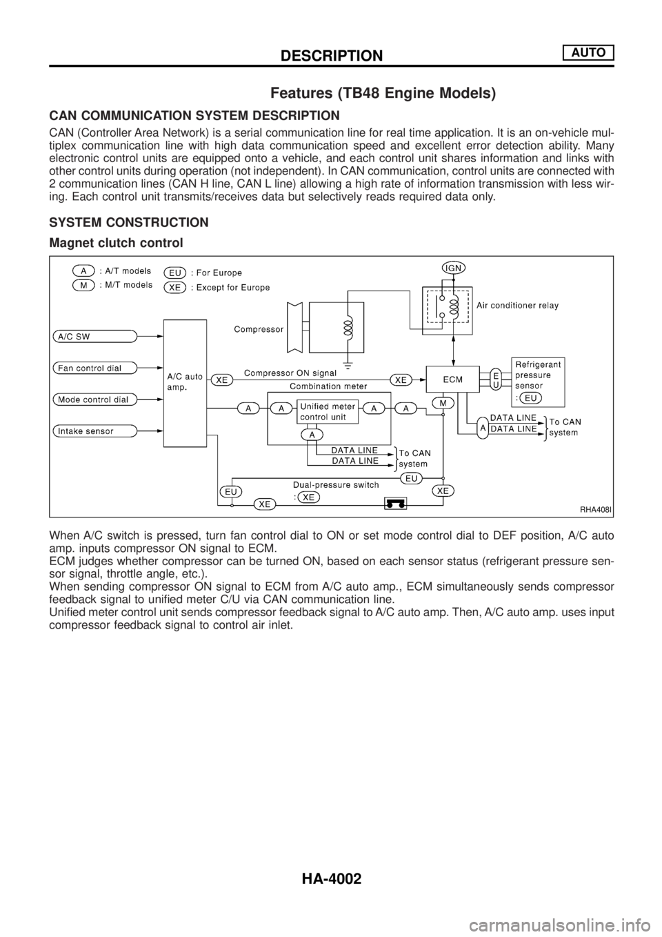
When A/C switch is pressed, turn fan control dial to ON or set mode control dial to DEF position, A/C auto
amp. inputs compressor ON signal to ECM.
ECM judges whether compressor can be turned ON, based on each sensor status (refrigerant pressure sen-
sor signal, throttle angle, etc.).
When sending compressor ON signal to ECM from A/C auto amp., ECM simultaneously sends compressor
feedback signal to uni®ed meter C/U via CAN communication line.
Uni®ed meter control unit sends compressor feedback signal to A/C auto amp. Then, A/C auto amp. uses input
compressor feedback signal to control air inlet.
RHA408I
DESCRIPTIONAUTO
HA-4002
Page 509 of 579
jC
STEP 4 - OPERATION OF EACH ACTUA-
TOR IS CHECKED.
Engine running.
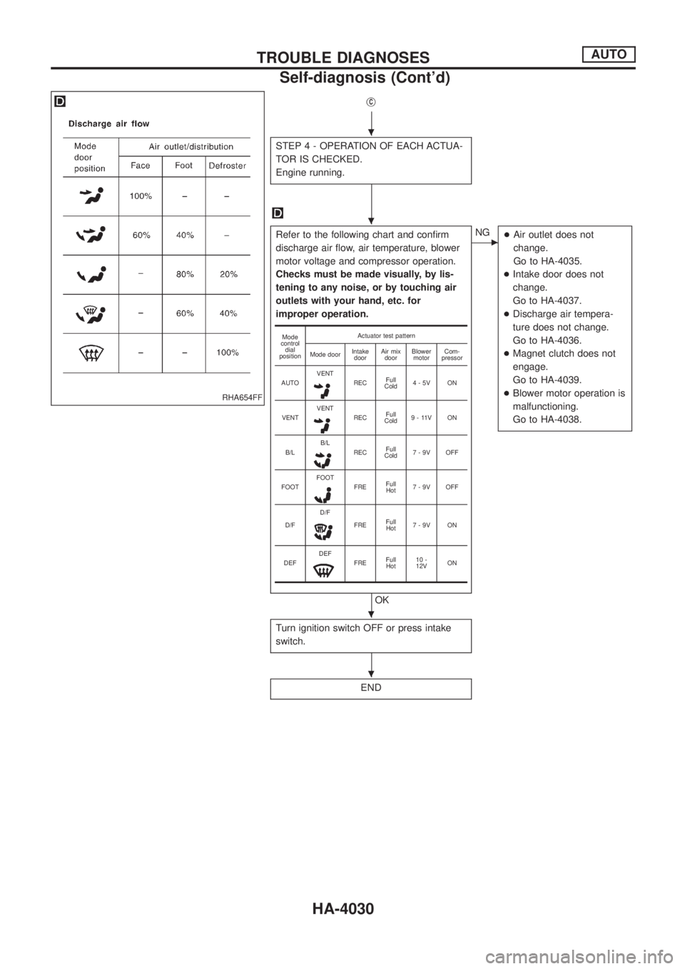
Refer to the following chart and con®rm
discharge air ¯ow, air temperature, blower
motor voltage and compressor operation.
Checks must be made visually, by lis-
tening to any noise, or by touching air
outlets with your hand, etc. for
improper operation.
OK
cNG
+Air outlet does not
change.
Go to HA-4035.
+Intake door does not
change.
Go to HA-4037.
+Discharge air tempera-
ture does not change.
Go to HA-4036.
+Magnet clutch does not
engage.
Go to HA-4039.
+Blower motor operation is
malfunctioning.
Go to HA-4038.
Turn ignition switch OFF or press intake
switch.
END
Mode
control
dial
positionActuator test pattern
Mode doorIntake
doorAir mix
doorBlower
motorCom-
pressor
AUTOVENT
RECFull
Cold4-5V ON
VENTVENT
RECFull
Cold9 - 11V ON
B/LB/L
RECFull
Cold7-9V OFF
FOOTFOOT
FREFull
Hot7-9V OFF
D/FD/F
FREFull
Hot7-9V ON
DEFDEF
FREFull
Hot10 -
12VON
RHA654FF
.
.
.
.
TROUBLE DIAGNOSESAUTO
Self-diagnosis (Cont'd)
HA-4030
Page 519 of 579

DIAGNOSTIC PROCEDURE (TB48 ENGINE EXCEPT
FOR THE MIDDLE EAST)
SYMPTOM: Magnet clutch does not engage when A/C switch
and fan control dial are ON.
CHECK INTAKE SENSOR CIRCUIT.
Refer to self-diagnosis (HA-4027) and
intake sensor circuit (HA-132 in Y61 SER-
VICE MANUAL, publication No. SM7E-
2Y61G1.)
CHECK POWER SUPPLY FOR COM-
PRESSOR.
Disconnect compressor harness connector.
Do approx. 12 volts exist between compres-
sor harness connector terminal No.j
1and
ground?
No
cYe s
Check magnet clutch coil.
NG
Replace magnet clutch.
Refer to HA-178 in Y61
SERVICE MANUAL (publi-
cation No. SM7E-2Y61G1).
Disconnect A/C relay.
Note
CHECK CIRCUIT CONTINUITY
BETWEEN A/C RELAY HARNESS CON-
NECTOR TERMINAL NO.j
3AND COM-
PRESSOR HARNESS CONNECTOR TER-
MINAL NO.j
1.
Continuity should exist.
If OK, check harness for short.
OK
CHECK POWER SUPPLY FOR A/C
RELAY.
Disconnect A/C relay.
Do approx. 12 volts exist between A/C
relay harness connector terminal Nos.j
1,
j5and ground?
Ye s
cNo
Check power supply circuit
and 10A or 20A (No.
)
located in the fuse block
(J/B).
Refer to EL section (ªWiring
Diagramº, ªPOWER SUP-
PLY ROUTINGº).
CHECK A/C RELAY AFTER DISCON-
NECTING IT.
Refer to HA-41 in Y61 SERVICE MANUAL,
publication No. SM1E-Y61EG1.
OK
cNG
Replace A/C relay.
jA(Go to next page.)
Note:
If the result is NG or No after checking circuit continuity, repair harness or
connector.
RHA385I
SHA579F
SHA580FC
SHA581F
.
.
.
.
.
.
.
TROUBLE DIAGNOSESAUTO
Magnet Clutch (Cont'd)
HA-4040
Page 522 of 579
DIAGNOSTIC PROCEDURE (MODELS WITH TB45
ENGINE)
SYMPTOM: Magnet clutch does not engage when A/C switch
and fan control dial are ON.
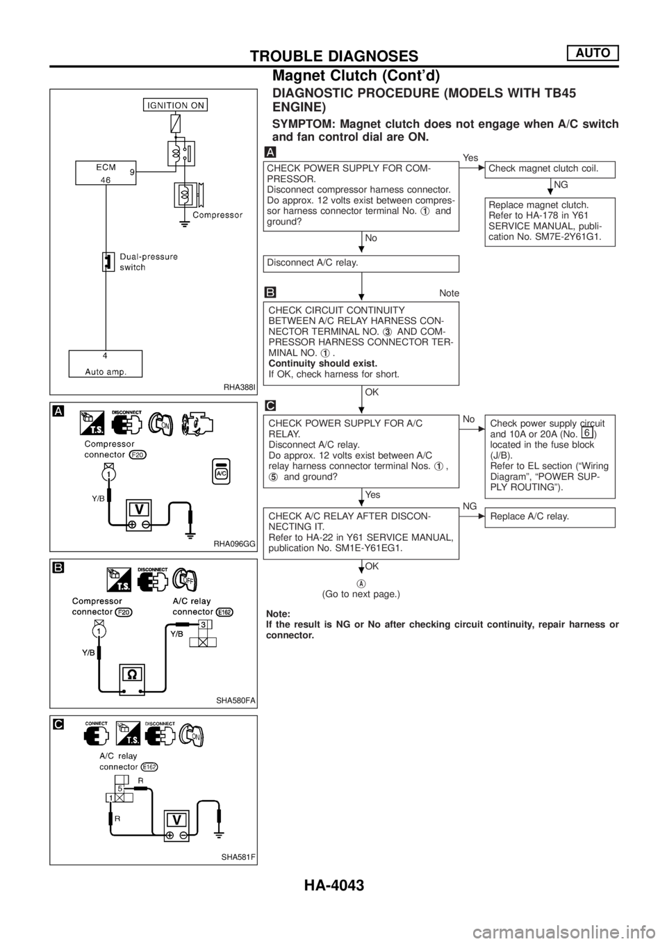
CHECK POWER SUPPLY FOR COM-
PRESSOR.
Disconnect compressor harness connector.
Do approx. 12 volts exist between compres-
sor harness connector terminal No.j
1and
ground?
No
cYe s
Check magnet clutch coil.
NG
Replace magnet clutch.
Refer to HA-178 in Y61
SERVICE MANUAL, publi-
cation No. SM7E-2Y61G1.
Disconnect A/C relay.
Note
CHECK CIRCUIT CONTINUITY
BETWEEN A/C RELAY HARNESS CON-
NECTOR TERMINAL NO.j
3AND COM-
PRESSOR HARNESS CONNECTOR TER-
MINAL NO.j
1.
Continuity should exist.
If OK, check harness for short.
OK
CHECK POWER SUPPLY FOR A/C
RELAY.
Disconnect A/C relay.
Do approx. 12 volts exist between A/C
relay harness connector terminal Nos.j
1,
j5and ground?
Ye s
cNo
Check power supply circuit
and 10A or 20A (No.
)
located in the fuse block
(J/B).
Refer to EL section (ªWiring
Diagramº, ªPOWER SUP-
PLY ROUTINGº).
CHECK A/C RELAY AFTER DISCON-
NECTING IT.
Refer to HA-22 in Y61 SERVICE MANUAL,
publication No. SM1E-Y61EG1.
OK
cNG
Replace A/C relay.
jA(Go to next page.)
Note:
If the result is NG or No after checking circuit continuity, repair harness or
connector.
RHA388I
RHA096GG
SHA580FA
SHA581F
.
.
.
.
.
.
TROUBLE DIAGNOSESAUTO
Magnet Clutch (Cont'd)
HA-4043
Page 525 of 579
DIAGNOSTIC PROCEDURE (MODELS WITH TD
ENGINE)
SYMPTOM: Magnet clutch does not engage when A/C switch
and fan control dial are ON.
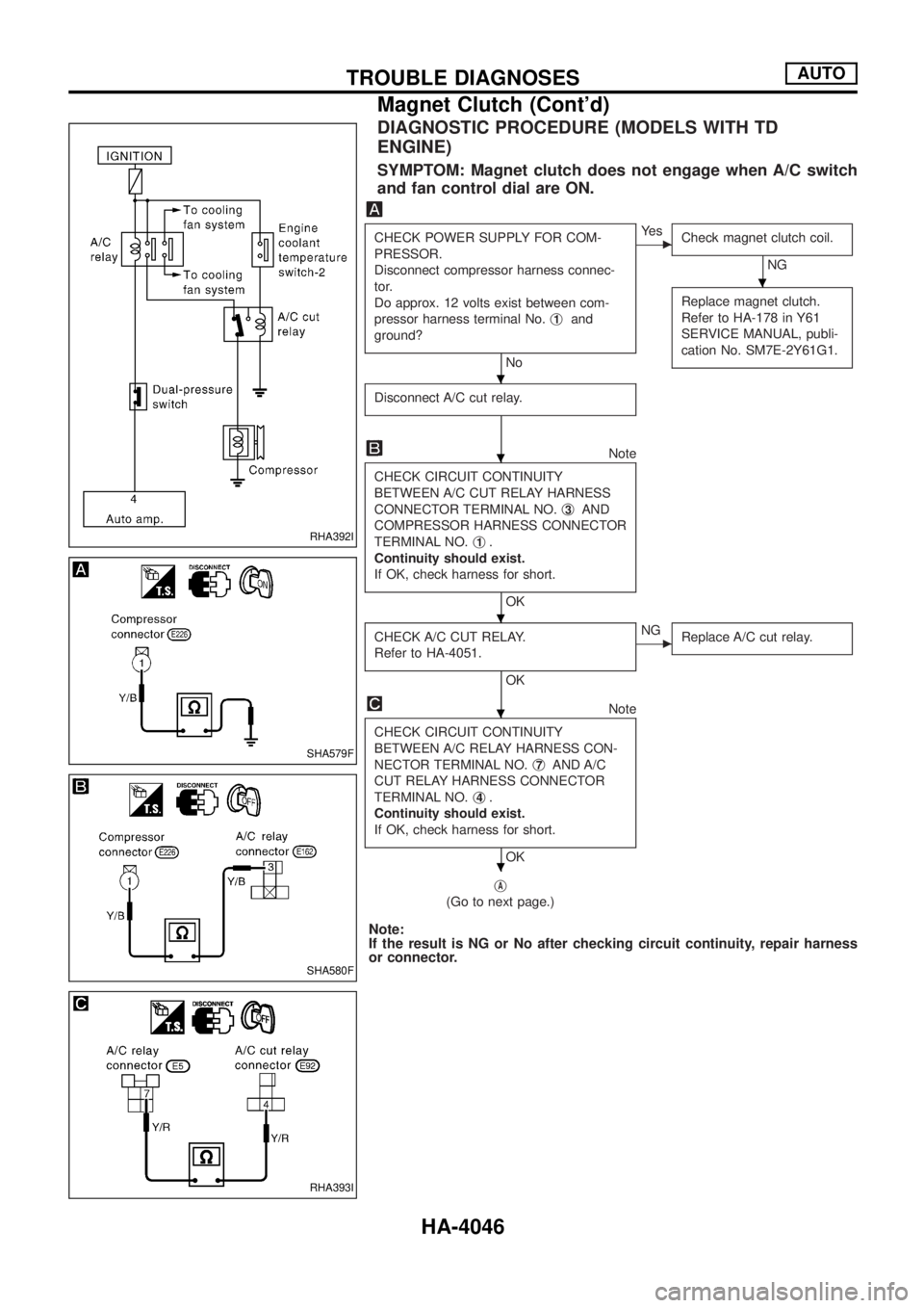
CHECK POWER SUPPLY FOR COM-
PRESSOR.
Disconnect compressor harness connec-
tor.
Do approx. 12 volts exist between com-
pressor harness terminal No.j
1and
ground?
No
cYe s
Check magnet clutch coil.
NG
Replace magnet clutch.
Refer to HA-178 in Y61
SERVICE MANUAL, publi-
cation No. SM7E-2Y61G1.
Disconnect A/C cut relay.
Note
CHECK CIRCUIT CONTINUITY
BETWEEN A/C CUT RELAY HARNESS
CONNECTOR TERMINAL NO.j
3AND
COMPRESSOR HARNESS CONNECTOR
TERMINAL NO.j
1.
Continuity should exist.
If OK, check harness for short.
OK
CHECK A/C CUT RELAY.
Refer to HA-4051.
OK
cNG
Replace A/C cut relay.
Note
CHECK CIRCUIT CONTINUITY
BETWEEN A/C RELAY HARNESS CON-
NECTOR TERMINAL NO.j
7AND A/C
CUT RELAY HARNESS CONNECTOR
TERMINAL NO.j
4.
Continuity should exist.
If OK, check harness for short.
OK
j
A
(Go to next page.)
Note:
If the result is NG or No after checking circuit continuity, repair harness
or connector.
RHA392I
SHA579F
SHA580F
RHA393I
.
.
.
.
.
.
TROUBLE DIAGNOSESAUTO
Magnet Clutch (Cont'd)
HA-4046
Page 528 of 579
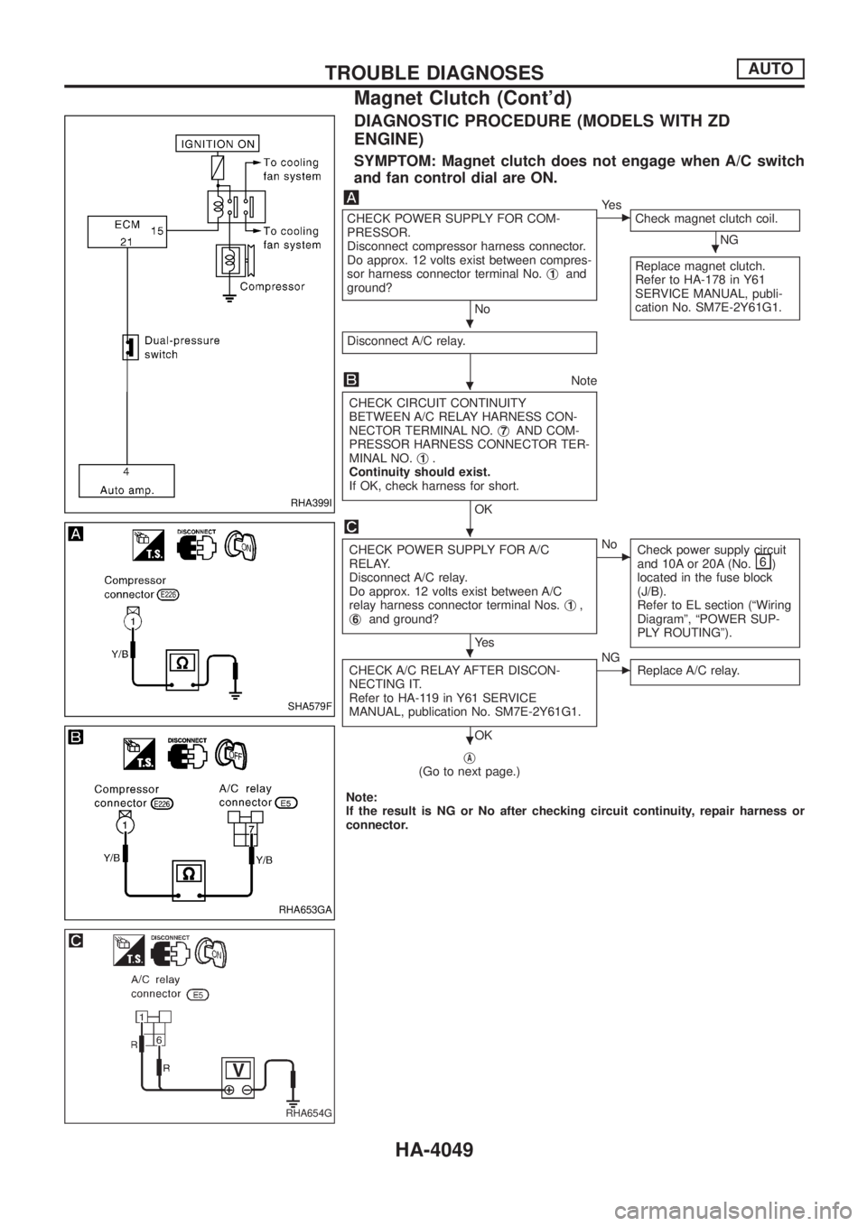
DIAGNOSTIC PROCEDURE (MODELS WITH ZD
ENGINE)
SYMPTOM: Magnet clutch does not engage when A/C switch
and fan control dial are ON.
CHECK POWER SUPPLY FOR COM-
PRESSOR.
Disconnect compressor harness connector.
Do approx. 12 volts exist between compres-
sor harness connector terminal No.j
1and
ground?
No
cYe s
Check magnet clutch coil.
NG
Replace magnet clutch.
Refer to HA-178 in Y61
SERVICE MANUAL, publi-
cation No. SM7E-2Y61G1.
Disconnect A/C relay.
Note
CHECK CIRCUIT CONTINUITY
BETWEEN A/C RELAY HARNESS CON-
NECTOR TERMINAL NO.j
7AND COM-
PRESSOR HARNESS CONNECTOR TER-
MINAL NO.j
1.
Continuity should exist.
If OK, check harness for short.
OK
CHECK POWER SUPPLY FOR A/C
RELAY.
Disconnect A/C relay.
Do approx. 12 volts exist between A/C
relay harness connector terminal Nos.j
1,
j6and ground?
Ye s
cNo
Check power supply circuit
and 10A or 20A (No.
)
located in the fuse block
(J/B).
Refer to EL section (ªWiring
Diagramº, ªPOWER SUP-
PLY ROUTINGº).
CHECK A/C RELAY AFTER DISCON-
NECTING IT.
Refer to HA-119 in Y61 SERVICE
MANUAL, publication No. SM7E-2Y61G1.
OK
cNG
Replace A/C relay.
jA(Go to next page.)
Note:
If the result is NG or No after checking circuit continuity, repair harness or
connector.
RHA399I
SHA579F
RHA653GA
RHA654G
.
.
.
.
.
.
TROUBLE DIAGNOSESAUTO
Magnet Clutch (Cont'd)
HA-4049
Page 548 of 579
Illumination ..................................................EL-4079
Instrument panel .........................................BT-4006
Intake door motor .......................................HA-4037
Interior lamp ................................................EL-4088
K
Keyless entry system - See Multi-re-
mote control system ................................EL-4264
L
Length (Dimensions) ...................................GI-4008
License lamp ...............................................EL-4049
Line pressure test (A/T) ..............................AT-4014
LOAD - Wiring diagram .........EC-4008, 4016, 4025
Location of electrical units ..........................EL-4300
M
MAFS - Wiring diagram..............................EC-4049
Magnet clutch .............................................HA-4039
Maintenance...............................................MA-4003
Maintenance (engine) ................................MA-4003
Major overhaul (Transfer) .................TF-4002, 4003
Mass air ¯ow sensor (MAFS).....................EC-4047
Meter ...........................................................EL-4095
METER - Wiring diagram............................EL-4097
MIRROR - Wiring diagram..........................EL-4227
Mode door motor ........................................HA-4035
Model variation ............................................GI-4005
MULTI - Wiring diagram ...................EL-4264, 4266
Multi-remote control system........................EL-4264
N
NATS (Nissan anti-theft system) ......EL-4293, 4295
NATS - Wiring diagram ..........EL-4293, 4295, 4297
NAVI - Wiring diagram ................................EL-4175
Navigation System ......................................EL-4162
P
P/ANT - Wiring diagram..............................EL-4159
Parking lamp ...............................................EL-4049
POWER - Wiring diagram...........................EL-4006
Power door lock ..........................................EL-4244
Power supply routing ..................................EL-4005
Power window .............................................EL-4238
Pressure test (A/T) ......................................AT-4014Q
Quick-glow system .....................................EC-4031
R
Radio - See Audio.......................................EL-4136
R/COOL - Wiring diagram (front auto
A/C).........................................................HA-4055
R/COOL - Wiring diagram (front
manual A/C) ............................................HA-4057
Rear bumper ...............................................BT-4005
Rear seat ....................................................BT-4012
Rear seat belt .............................................RS-4013
Rear window defogger ................................EL-4126
REMOTE - Wiring diagram .........................EL-4155
R/FOG - Wiring diagram .............................EL-4064
R/HEAT - Wiring diagram ...........................HA-4003
Road wheel size ..........................................GI-4009
Room lamp - See Interior lamp ..................EL-4088
ROOM/L - Wiring diagram ..........................EL-4089
S
Seat belt, rear.............................................RS-4013
Seat, rear ....................................................BT-4012
Seat, second (2nd) .....................................BT-4012
Second (2nd) seat ......................................BT-4012
Shift schedule..............................................AT-4014
SMJ (super multiple junction) .......................Foldout
Speedometer...............................................EL-4095
SRS - Wiring diagram ................................RS-4003
STAB - Wiring diagram ..............................RA-4002
Stabilizer release device ............................RA-4002
Stabilizer release device - Wiring
diagram ...................................................RA-4002
Stall test (A/T) .............................................AT-4014
S/TANK - Wiring diagram ...........................FE-4004
Steering switch............................................EL-4036
Stop lamp ....................................................EL-4059
STOP/L - Wiring diagram............................EL-4059
Sub fuel tank control system ......................FE-4002
Super lock ...................................................EL-4290
Supplemental restraint system - Wiring
diagram ...................................................RS-4003
T
Tachometer .................................................EL-4095
Tail lamp ......................................................EL-4049
TAIL/L - Wiring diagram ..............................EL-4049
TCM circuit diagram ..........................AT-4002, 4011
Telephone....................................................EL-4161
THEFT - Wiring diagram ..................EL-4279, 4284
Theft warning system..................................EL-4278
ALPHABETICAL INDEX
IDX-4003