2004 NISSAN PATROL OD OFF
[x] Cancel search: OD OFFPage 16 of 579
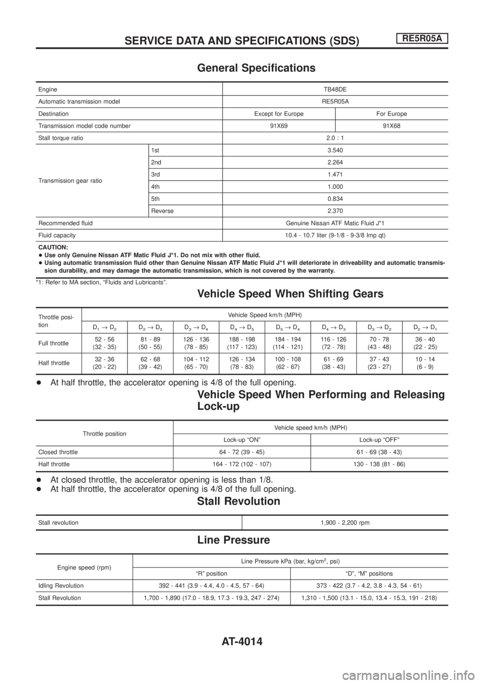
General Speci®cations
EngineTB48DE
Automatic transmission modelRE5R05A
Destination Except for Europe For Europe
Transmission model code number 91X69 91X68
Stall torque ratio2.0:1
Transmission gear ratio1st 3.540
2nd 2.264
3rd 1.471
4th 1.000
5th 0.834
Reverse 2.370
Recommended ¯uid Genuine Nissan ATF Matic Fluid J*1
Fluid capacity10.4 - 10.7 liter (9-1/8 - 9-3/8 Imp qt)
CAUTION:
+Use only Genuine Nissan ATF Matic Fluid J*1. Do not mix with other ¯uid.
+Using automatic transmission ¯uid other than Genuine Nissan ATF Matic Fluid J*1 will deteriorate in driveability and automatic transmis-
sion durability, and may damage the automatic transmission, which is not covered by the warranty.
*1: Refer to MA section, ªFluids and Lubricantsº.
Vehicle Speed When Shifting Gears
Throttle posi-
tionVehicle Speed km/h (MPH)
D
1®D2D2®D3D3®D4D4®D5D5®D4D4®D3D3®D2D2®D1
Full throttle52-56
(32 - 35)81-89
(50 - 55)126 - 136
(78 - 85)188 - 198
(117 - 123)184 - 194
(114 - 121)116 - 126
(72 - 78)70-78
(43 - 48)36-40
(22 - 25)
Half throttle32-36
(20 - 22)62-68
(39 - 42)104 - 112
(65 - 70)126 - 134
(78 - 83)100 - 108
(62 - 67)61-69
(38 - 43)37-43
(23 - 27)10-14
(6-9)
+At half throttle, the accelerator opening is 4/8 of the full opening.
Vehicle Speed When Performing and Releasing
Lock-up
Throttle positionVehicle speed km/h (MPH)
Lock-up ªONº Lock-up ªOFFº
Closed throttle 64 - 72 (39 - 45) 61 - 69 (38 - 43)
Half throttle 164 - 172 (102 - 107) 130 - 138 (81 - 86)
+At closed throttle, the accelerator opening is less than 1/8.
+At half throttle, the accelerator opening is 4/8 of the full opening.
Stall Revolution
Stall revolution1,900 - 2,200 rpm
Line Pressure
Engine speed (rpm)Line Pressure kPa (bar, kg/cm
2, psi)
ªRº position ªDº, ªMº positions
Idling Revolution 392 - 441 (3.9 - 4.4, 4.0 - 4.5, 57 - 64) 373 - 422 (3.7 - 4.2, 3.8 - 4.3, 54 - 61)
Stall Revolution 1,700 - 1,890 (17.0 - 18.9, 17.3 - 19.3, 247 - 274) 1,310 - 1,500 (13.1 - 15.0, 13.4 - 15.3, 191 - 218)
SERVICE DATA AND SPECIFICATIONS (SDS)RE5R05A
AT-4014
Page 17 of 579
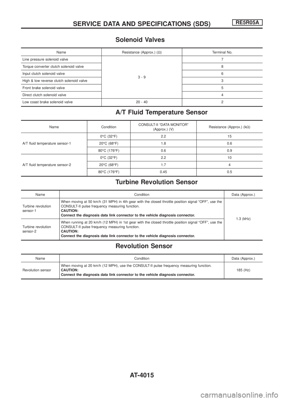
Solenoid Valves
Name Resistance (Approx.) (W) Terminal No.
Line pressure solenoid valve
3-97
Torque converter clutch solenoid valve8
Input clutch solenoid valve6
High & low reverse clutch solenoid valve3
Front brake solenoid valve5
Direct clutch solenoid valve4
Low coast brake solenoid valve 20 - 40 2
A/T Fluid Temperature Sensor
Name ConditionCONSULT-II ªDATA MONITORº
(Approx.) (V)Resistance (Approx.) (kW)
A/T ¯uid temperature sensor-10ÉC (32ÉF) 2.2 15
20ÉC (68ÉF) 1.8 0.6
80ÉC (176ÉF) 0.6 0.9
A/T ¯uid temperature sensor-20ÉC (32ÉF) 2.2 10
20ÉC (68ÉF) 1.7 4
80ÉC (176ÉF) 0.45 0.5
Turbine Revolution Sensor
Name Condition Data (Approx.)
Turbine revolution
sensor-1When moving at 50 km/h (31 MPH) in 4th gear with the closed throttle position signal ªOFFº, use the
CONSULT-II pulse frequency measuring function.
CAUTION:
Connect the diagnosis data link connector to the vehicle diagnosis connector.
1.3 (kHz)
Turbine revolution
sensor-2When running at 20 km/h (12 MPH) in 1st gear with the closed throttle position signal ªOFFº, use the
CONSULT-II pulse frequency measuring function.
CAUTION:
Connect the diagnosis data link connector to the vehicle diagnosis connector.
Revolution Sensor
Name Condition Data (Approx.)
Revolution sensorWhen moving at 20 km/h (12 MPH), use the CONSULT-II pulse frequency measuring function.
CAUTION:
Connect the diagnosis data link connector to the vehicle diagnosis connector.185 (Hz)
SERVICE DATA AND SPECIFICATIONS (SDS)RE5R05A
AT-4015
Page 44 of 579
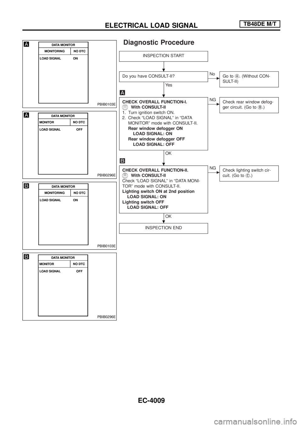
Diagnostic Procedure
INSPECTION START
Do you have CONSULT-II?
Ye s
cNo
Go tojA. (Without CON-
SULT-II)
CHECK OVERALL FUNCTION-I.
With CONSULT-II
1. Turn ignition switch ON.
2. Check ªLOAD SIGNALº in ªDATA
MONITORº mode with CONSULT-II.
Rear window defogger ON
LOAD SIGNAL: ON
Rear window defogger OFF
LOAD SIGNAL: OFF
OK
cNG
Check rear window defog-
ger circuit. (Go toj
B.)
CHECK OVERALL FUNCTION-II.
With CONSULT-II
Check ªLOAD SIGNALº in ªDATA MONI-
TORº mode with CONSULT-II.
Lighting switch ON at 2nd position
LOAD SIGNAL: ON
Lighting switch OFF
LOAD SIGNAL: OFF
OK
cNG
Check lighting switch cir-
cuit. (Go toj
C.)
INSPECTION END
PBIB0103E
PBIB0296E
PBIB0103E
PBIB0296E
.
.
.
.
ELECTRICAL LOAD SIGNALTB48DE M/T
EC-4009
Page 45 of 579
jA
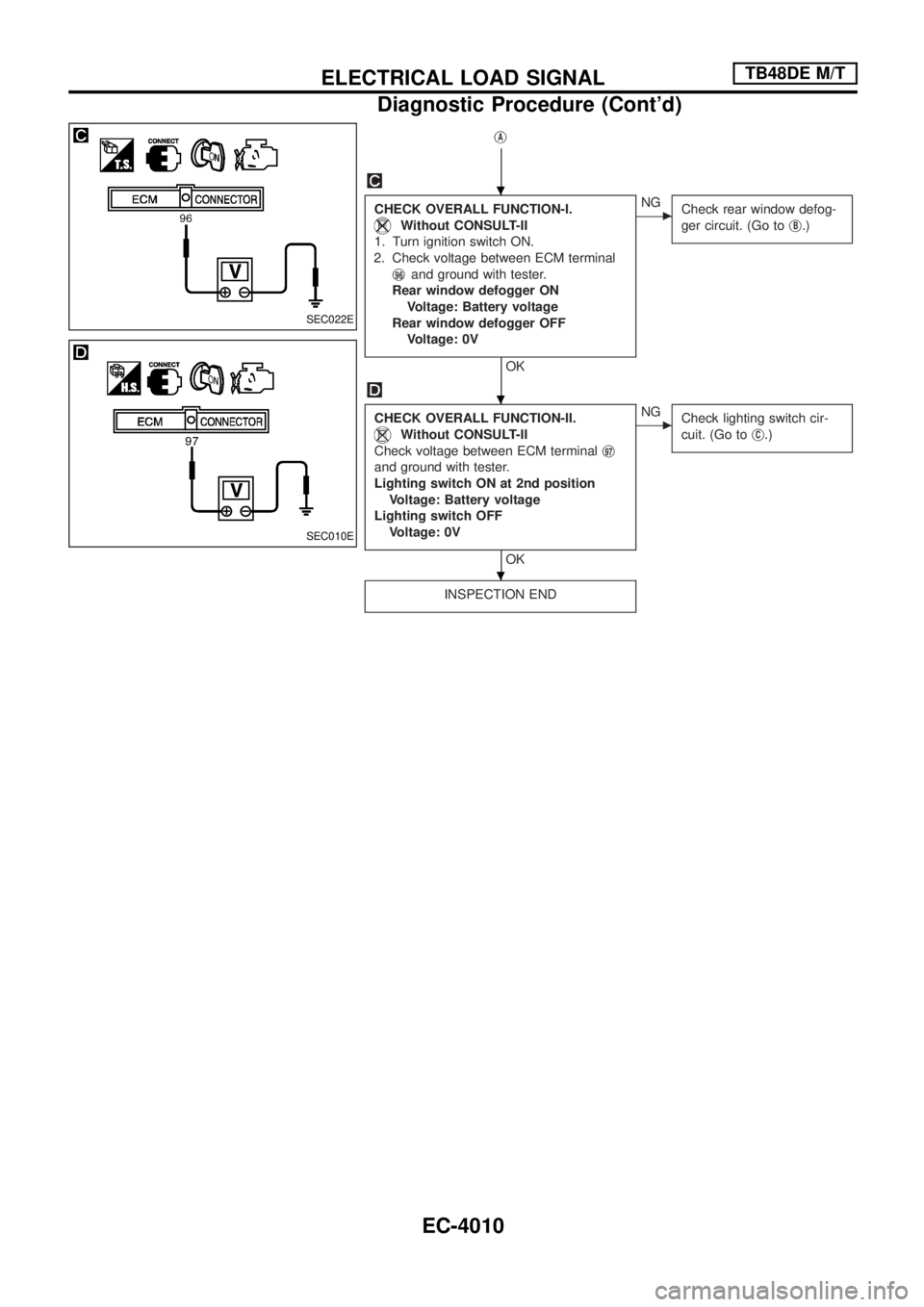
CHECK OVERALL FUNCTION-I.
Without CONSULT-II
1. Turn ignition switch ON.
2. Check voltage between ECM terminal
j
96and ground with tester.
Rear window defogger ON
Voltage: Battery voltage
Rear window defogger OFF
Voltage: 0V
OK
cNG
Check rear window defog-
ger circuit. (Go toj
B.)
CHECK OVERALL FUNCTION-II.
Without CONSULT-II
Check voltage between ECM terminalj
97
and ground with tester.
Lighting switch ON at 2nd position
Voltage: Battery voltage
Lighting switch OFF
Voltage: 0V
OK
cNG
Check lighting switch cir-
cuit. (Go toj
C.)
INSPECTION END
SEC022E
SEC010E
.
.
.
ELECTRICAL LOAD SIGNALTB48DE M/T
Diagnostic Procedure (Cont'd)
EC-4010
Page 47 of 579
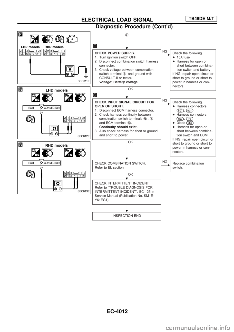
jC
CHECK POWER SUPPLY.
1. Turn ignition switch OFF.
2. Disconnect combination switch harness
connector.
3. Check voltage between combination
switch terminalj
5and ground with
CONSULT-II or tester.
Voltage: Battery voltage
OK
cNG
Check the following.
+15A fuse
+Harness for open or
short between combina-
tion switch and battery
If NG, repair open circuit or
short to ground or short to
power in harness or con-
nectors.
CHECK INPUT SIGNAL CIRCUIT FOR
OPEN OR SHORT.
1. Disconnect ECM harness connector.
2. Check harness continuity between
combination switch terminalsj
6,j7
and ECM terminalj97.
Continuity should exist.
3. Also check harness for short to ground
and short to power.
OK
cNG
Check the following.
+Harness connectors
E127,M21
+Harness connectors
M50,F5
+DiodeE108
+Harness for open or
short between combina-
tion switch and ECM
If NG, repair open circuit or
short to ground or short to
power in harness or con-
nectors.
CHECK COMBINATION SWITCH.
Refer to EL section.
OK
cNG
Replace combination
switch.
CHECK INTERMITTENT INCIDENT.
Refer to ªTROUBLE DIAGNOSIS FOR
INTERMITTENT INCIDENTº, EC-125 in
Service Manual (Publication No. SM1E-
Y61EG1).
INSPECTION END
SEC011E
SEC012E
SEC013E
.
.
.
.
.
ELECTRICAL LOAD SIGNALTB48DE M/T
Diagnostic Procedure (Cont'd)
EC-4012
Page 73 of 579
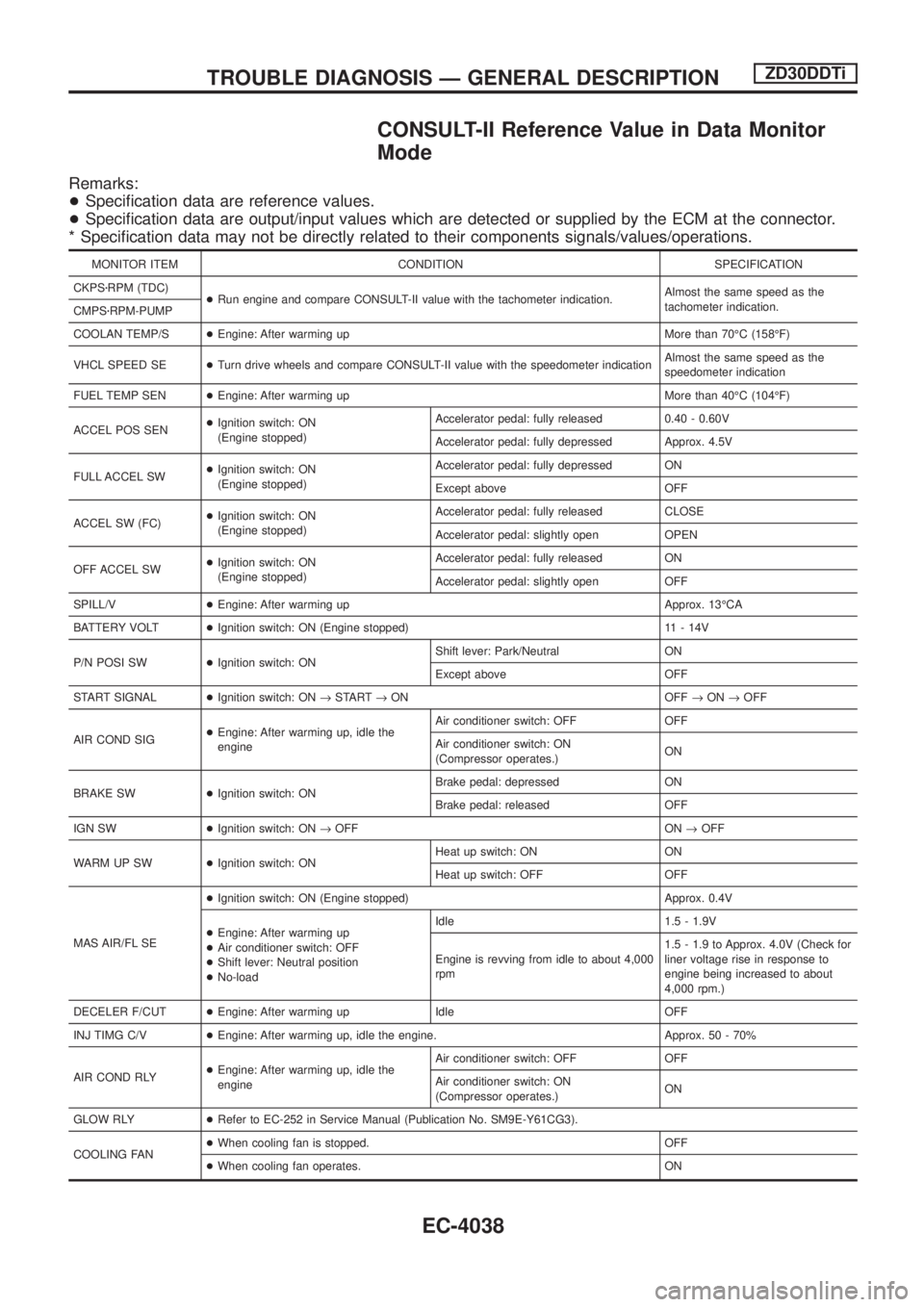
CONSULT-II Reference Value in Data Monitor
Mode
Remarks:
+Speci®cation data are reference values.
+Speci®cation data are output/input values which are detected or supplied by the ECM at the connector.
* Speci®cation data may not be directly related to their components signals/values/operations.
MONITOR ITEM CONDITION SPECIFICATION
CKPSzRPM (TDC)
+Run engine and compare CONSULT-II value with the tachometer indication.Almost the same speed as the
tachometer indication.
CMPSzRPM-PUMP
COOLAN TEMP/S+Engine: After warming up More than 70ÉC (158ÉF)
VHCL SPEED SE+Turn drive wheels and compare CONSULT-II value with the speedometer indicationAlmost the same speed as the
speedometer indication
FUEL TEMP SEN+Engine: After warming up More than 40ÉC (104ÉF)
ACCEL POS SEN+Ignition switch: ON
(Engine stopped)Accelerator pedal: fully released 0.40 - 0.60V
Accelerator pedal: fully depressed Approx. 4.5V
FULL ACCEL SW+Ignition switch: ON
(Engine stopped)Accelerator pedal: fully depressed ON
Except above OFF
ACCEL SW (FC)+Ignition switch: ON
(Engine stopped)Accelerator pedal: fully released CLOSE
Accelerator pedal: slightly open OPEN
OFF ACCEL SW+Ignition switch: ON
(Engine stopped)Accelerator pedal: fully released ON
Accelerator pedal: slightly open OFF
SPILL/V+Engine: After warming up Approx. 13ÉCA
BATTERY VOLT+Ignition switch: ON (Engine stopped) 11 - 14V
P/N POSI SW+Ignition switch: ONShift lever: Park/Neutral ON
Except above OFF
START SIGNAL+Ignition switch: ON®START®ON OFF®ON®OFF
AIR COND SIG+Engine: After warming up, idle the
engineAir conditioner switch: OFF OFF
Air conditioner switch: ON
(Compressor operates.)ON
BRAKE SW+Ignition switch: ONBrake pedal: depressed ON
Brake pedal: released OFF
IGN SW+Ignition switch: ON®OFF ON®OFF
WARM UP SW+Ignition switch: ONHeat up switch: ON ON
Heat up switch: OFF OFF
MAS AIR/FL SE+Ignition switch: ON (Engine stopped) Approx. 0.4V
+Engine: After warming up
+Air conditioner switch: OFF
+Shift lever: Neutral position
+No-loadIdle 1.5 - 1.9V
Engine is revving from idle to about 4,000
rpm1.5 - 1.9 to Approx. 4.0V (Check for
liner voltage rise in response to
engine being increased to about
4,000 rpm.)
DECELER F/CUT+Engine: After warming up Idle OFF
INJ TIMG C/V+Engine: After warming up, idle the engine. Approx. 50 - 70%
AIR COND RLY+Engine: After warming up, idle the
engineAir conditioner switch: OFF OFF
Air conditioner switch: ON
(Compressor operates.)ON
GLOW RLY+Refer to EC-252 in Service Manual (Publication No. SM9E-Y61CG3).
COOLING FAN+When cooling fan is stopped. OFF
+When cooling fan operates. ON
TROUBLE DIAGNOSIS Ð GENERAL DESCRIPTIONZD30DDTi
EC-4038
Page 74 of 579
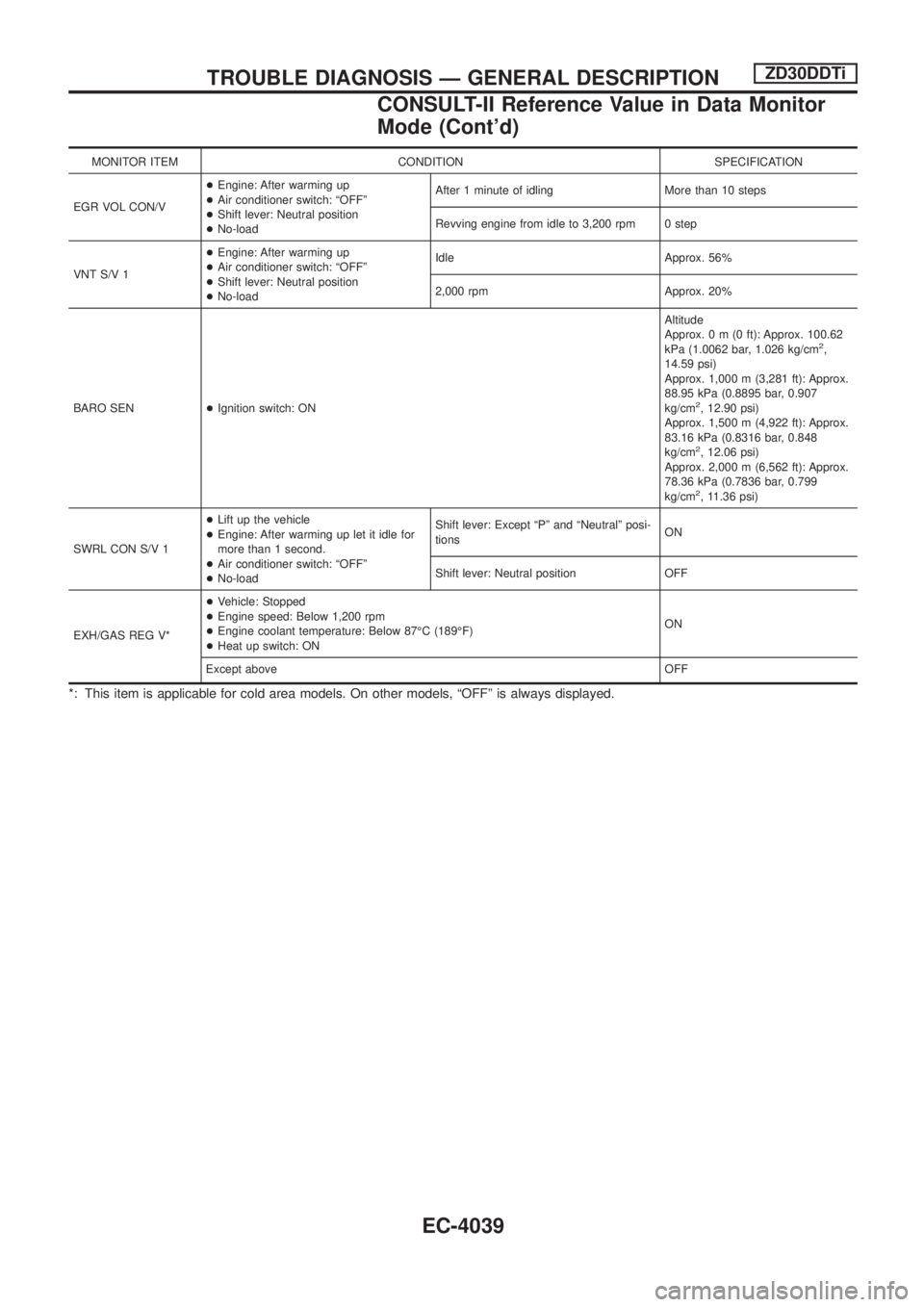
MONITOR ITEM CONDITION SPECIFICATION
EGR VOL CON/V+Engine: After warming up
+Air conditioner switch: ªOFFº
+Shift lever: Neutral position
+No-loadAfter 1 minute of idling More than 10 steps
Revving engine from idle to 3,200 rpm 0 step
VNT S/V 1+Engine: After warming up
+Air conditioner switch: ªOFFº
+Shift lever: Neutral position
+No-loadIdle Approx. 56%
2,000 rpm Approx. 20%
BARO SEN+Ignition switch: ONAltitude
Approx.0m(0ft): Approx. 100.62
kPa (1.0062 bar, 1.026 kg/cm
2,
14.59 psi)
Approx. 1,000 m (3,281 ft): Approx.
88.95 kPa (0.8895 bar, 0.907
kg/cm
2, 12.90 psi)
Approx. 1,500 m (4,922 ft): Approx.
83.16 kPa (0.8316 bar, 0.848
kg/cm
2, 12.06 psi)
Approx. 2,000 m (6,562 ft): Approx.
78.36 kPa (0.7836 bar, 0.799
kg/cm
2, 11.36 psi)
SWRL CON S/V 1+Lift up the vehicle
+Engine: After warming up let it idle for
more than 1 second.
+Air conditioner switch: ªOFFº
+No-loadShift lever: Except ªPº and ªNeutralº posi-
tionsON
Shift lever: Neutral position OFF
EXH/GAS REG V*+Vehicle: Stopped
+Engine speed: Below 1,200 rpm
+Engine coolant temperature: Below 87ÉC (189ÉF)
+Heat up switch: ONON
Except aboveOFF
*: This item is applicable for cold area models. On other models, ªOFFº is always displayed.
TROUBLE DIAGNOSIS Ð GENERAL DESCRIPTIONZD30DDTi
CONSULT-II Reference Value in Data Monitor
Mode (Cont'd)
EC-4039
Page 75 of 579
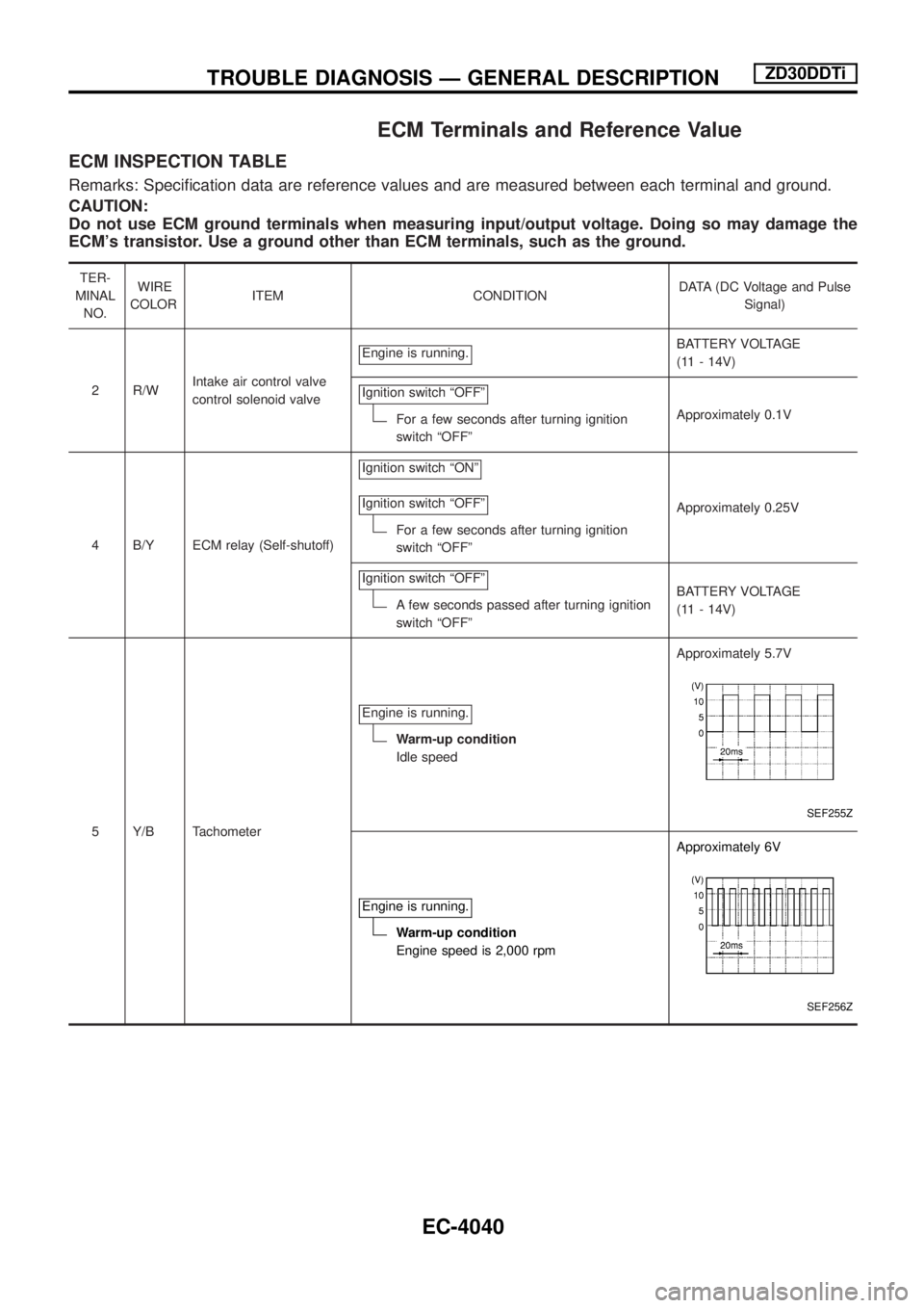
ECM Terminals and Reference Value
ECM INSPECTION TABLE
Remarks: Speci®cation data are reference values and are measured between each terminal and ground.
CAUTION:
Do not use ECM ground terminals when measuring input/output voltage. Doing so may damage the
ECM's transistor. Use a ground other than ECM terminals, such as the ground.
TER-
MINAL
NO.WIRE
COLORITEM CONDITIONDATA (DC Voltage and Pulse
Signal)
2 R/WIntake air control valve
control solenoid valveEngine is running.
BATTERY VOLTAGE
(11 - 14V)
Ignition switch ªOFFº
For a few seconds after turning ignition
switch ªOFFºApproximately 0.1V
4 B/Y ECM relay (Self-shutoff)Ignition switch ªONº
Ignition switch ªOFFº
For a few seconds after turning ignition
switch ªOFFºApproximately 0.25V
Ignition switch ªOFFº
A few seconds passed after turning ignition
switch ªOFFºBATTERY VOLTAGE
(11 - 14V)
5 Y/B TachometerEngine is running.
Warm-up condition
Idle speedApproximately 5.7V
SEF255Z
Engine is running.
Warm-up condition
Engine speed is 2,000 rpmApproximately 6V
SEF256Z
TROUBLE DIAGNOSIS Ð GENERAL DESCRIPTIONZD30DDTi
EC-4040